Article

Fractional Order Graph Filters: Design and Implementation

School of Information Science and Technology, Fudan University, Shanghai 200433, China
*
Author to whom correspondence should be addressed.
Electronics 2021, 10(4), 437; https://doi.org/10.3390/electronics10040437
Submission received: 10 January 2021 / Revised: 31 January 2021 / Accepted: 5 February 2021 / Published: 10 February 2021
(This article belongs to the Section Circuit and Signal Processing)

Abstract

:
Existing graph filters, polynomial or rational, are mainly of integer order forms. However, there are some frequency responses which are not easily achieved by integer order approximation. It will substantially increase the flexibility of the filters if we relax the integer order to fractional ones. Motivated by fractional order models, we introduce the fractional order graph filters (FOGF), and propose to design the filter coefficients by genetic algorithm. In order to implement distributed computation on a graph, an FOGF can be approximated by the continued fraction expansion and transformed to an infinite impulse response graph filter.

1. Introduction

The theory of graph signal processing (GSP), developed over the last decade, generalizes the classic digital signal processing to the cases where the signal is defined on an irregular topology [1,2,3,4]. GSP merges algebraic and spectral graph theory with computational harmonic analysis to process such signals on graphs. GSP has resulted in advanced solutions to manifold applications, such as computational science [5], image analysis [6] and recommendation system [7,8]. Moreover, GSP can be used to extend convolutional neural networks (CNNs) to graph data, which is called graph convolutional networks (GCNs) [9].
Graph filters (GFs) [10,11,12,13] are one of the core tools in GSP, which inherits the fundamental methodology from classical digital signal processing. Recent advances in spectral graph theory provide us with the frequency domain on graphs via the graph Fourier transform (GFT), which can be utilized to define the concept of a filtering operation as well as convolution for signals defined on graphs [1]. In [14,15], the authors propose a definition of the graph fractional Fourier transform (GFRFT), which can be seen as a linear operator, rotating from the vertex domain to the graph frequency domain. Thus, GFRFT employs a different eigenspace from the GFT. Similar to classical frequency-domain filtering, GFs manipulate the signal by selectively amplifying or attenuating its graph frequency domain components. GFs have been adopted in applications such as signal analysis [16,17], classification [8,18], reconstruction [10,19], denoising [20,21], clustering [22] and topology identification [23].
According to [24], there are two prevailing design forms of GFs, rational and polynomial, which correspond to infinite impulse response (IIR) and finite impulse response (FIR). The rational GFs can provide flexibility and accuracy in design. The polynomial GF is easy to be implemented distributedly, since it is constructed by some localized operators [25]. Consequently, the computation complexity of polynomial GFs is usually lower than rational GFs [25,26]. Additionally, there are various methods to obtain a GF with an approximation of the desired response, including least-squares fitting [11] and Chebyshev polynomial fitting [27].
However, GFs with integer order polynomial or rational kernels suffer from limited degrees of design freedom, which makes it difficult to implement filters with demanding spectral characteristics. For example, integer order polynomial filters may not be flat enough in passband and stopband.
In classical filtering theory, some fractional order filters have a unique response which can not be achieved by the integer order elements [28,29,30]. In [31], the authors present a general procedure to design fractional order Butterworth filter, where the filter degree of freedom increases due to the extra independent fractional order parameters. The extra degrees of freedom allow the full manipulation of the filter specifications to obtain the desired response [32]. However, the existing GF design still focuses on the classical integer order filters [12,33]. It motivates us to propose and design fractional order GFs (FOGFs).
The building block of the classical time-domain filter is the time shift operator [34]. Similarly, an operator called graph shift is proposed to build GFs. If we implement a graph shift operator on a directed ring graph, we can get a similar result as a delay filter. It is natural to doubt whether the shift must be unit or not. In [35,36], the authors propose different definitions of fractional graph shift operators. In [35], the fractional graph shift operator derived from the fractional adjacency matrix, which can be viewed as an intermediate picture of a signal propagating through a network. In [36], the fractional graph shift operator is based on fractional graph Laplacian matrix. The fractional graph Laplacian matrix allows random walks with long-range dynamics providing a general framework for anomalous diffusion and navigation, and inducing dynamically the small-world property on any network. Compared with the GFRFT employing a different eigenspace, the fractional graph shift operator employs different eigenvalues but reserves the same eigenspace. Naturally, we can use the fractional graph shift operator as the building block of FOGF.
Next, we focus on the design of FOGFs. Many polynomial approximation methods have been proposed and employed in the design of GFs [25,33]. However, these methods are not suitable for FOGF. The traditional design methods of integer order filters can determine the maximum order first and then other filter coefficients. But the fractional order of each shift operator is hard to determine, which makes the design of FOGF more complex than the traditional ones. In view of the strong multi-objective optimization capability of the genetic algorithm (GA), we resort to GA to find the optimal order and coefficients of FOGFs.
In many applications, such as wireless sensor networks, we have limited communication range and computation resources. Therefore, it is critical to implement distributed FOGFs. We use the continued fraction equation (CFE) and the modified Lentz’s algorithm to approximate the fractional order graph shift by rational form GF [37,38]. It is feasible to implement rational form GF in a distributed way [10,11,39].
Our main contributions are as follows: (i) we propose the form of the FOGF. (ii) for the sake of fast implementation, we approximate the GF with CFE and implement it in a distributed method.

2. Preliminaries

2.1. Graph and Graph Signal

An undirected graph G consists of a vertex set V and a edge set E . For simplicity, we only discuss the undirected graph in this paper, instead of the directed graph. Usually, edges represent the physical connections or the intrinsic structures of data. The weight associated with each edge in the graph often represents the similarity between the two vertices it connects. The adjacency matrix W describes the weight of each edge, where W i j is the weight between vertex i and vertex j. The degree matrix D illustrates the connection level of each vertex, where D i i = i W i j . The Laplacian matrix, defined as L = D W , has an eigen-decomposition L = U Λ U T , where U is its orthonormal eigenbasis. Λ = d i a g ( λ 1 , , λ N ) is a diagonal matrix, and its diagonal elements λ i , i = 1 , 2 , , N constitute the spectrum of G . In addition, the normalized graph Laplacian matrix is defined as L n o r m = D 1 2 LD 1 2 .
The data defined on a graph can be formularized as a graph signal x , where x i represents the value at the i-th vertex in the graph. In another perspective of view, graph signal can be seen as a function x : V R N defined on the vertices of graph.
In classical DSP, the Fourier transform decomposes a signal into oscillating modes [34]. Similarly, the GFT, which is defined as
x ^ = U T x ,
allows us to analyze oscillations along the edges [1]. The inverse GFT is defined as
x = U x ^ .
The graph Laplacian eigenvector u i associated with low frequency λ i varies slowly across the graph, i.e., if two vertices are connected by an edge with a large weight, the values of the eigenvector at those locations are likely to be similar. The eigenvector associated with larger eigenvalue oscillates more rapidly and is more likely to have different values on vertices connected by an edge with high weight, as shown in Figure 1.
In Figure 1, we use a sensor network graph as an example. The edge weight of the sensor network graph is the reciprocal of the distance between 2 sensors, and each sensor only communicates with the 6 neighbor sensors. In Figure 1a, the constant eigenvector u 1 corresponds to the smallest graph frequency λ 1 = 0 . u 1 is similar to the DC component of the classical signal. The smooth Fiedler vector u 2 corresponds to the second smallest graph frequency λ 2 . It is widely used in spectral clustering to separate a graph into two parts [40].

2.2. Graph Shift

In classical DSP, the basic building block of filters is a special filter z 1 called the time shift or delay [34]. But its definition on graphs is not so obvious due to the rich underlying connectivity structure. Topologically, the signal shift on a graph can be viewed as the diffusion of a signal sample from the considered vertex along all edges connected to this vertex.
In GSP, the shift operator is extended to general graph signals x where the relational dependencies among the data are represented by an arbitrary graph. Graph shift operator (GSO) S has several different definitions [1]. If the values of the shifted signal are scaled by the weighting coefficients of the corresponding edges, then the shifted signal is given by Sx : = Wx . The Laplacian matrix version Lx can also be considered as a graph shift operator, since it is a combination of the scaled original signal Dx and the weighted shifted signal Wx .
When we design a fractional order filter, fractional calculus is the essential theory [41,42]. In [35], the authors propose the definition of fractional graph shift. The operation W α x is similar to the standard graph shift, where α R is not limited to integers.
Actually, the classical fractional shift operator can be seen as a fractional delay digital filter (FDDF), which is proposed in [41]. The ideal frequency response of FDDF is e j ω D , where D is called group delay or phase delay. The inverse Fourier transform of the frequency response is
h [ n ] = sin [ π ( n D ) ] π ( n D ) .
In Figure 2, it is obvious that the fractional shifted signal on a directed ring graph plays a similar role as the fractional delay filter in classical DSP. The fractional graph shift brings the phenomenon of interpolation, whose quality is bandwidth-dependent.

2.3. Graph Filtering

A GF H is a function h ( · ) applied to the shift operator L , i.e., H = h ( L ) . The eigen-decomposition of H is in the form H = U h ( Λ ) U , where h ( Λ ) is a diagonal matrix that highlights the filter’s impact on the graph frequencies λ 1 , λ 1 , , λ N . More specifically, the filter output y for a filter input x can be written as
y = Hx ,
which in the graph frequency domain can be translated into
y ^ = h ( Λ ) x ^ ,
where x ^ and y ^ represent the GFT of the input and output signal, respectively [39]. The concept of GFs is similar to the one used in traditional digital signal processing. However, depending on the underlying graph topology, the shift operators might not have a simple spectrum, i.e., the multiplicity of some eigenvalues is greater than one. Additionally, there is no one-to-one mapping between the graph frequencies and graph nodes.
In analogy with the pivotal role of the time shift in standard system theory, filtering graph signals can be implemented as a linear combination of a graph signal and its graph shifted versions. The output graph signal can then be written as
y = h 0 S 0 x + h 1 S 1 x + + h N S N x .
A popular form of H is a polynomial of the GSO S ,
H = k = 0 K h k S k ,
which we refer to as FIR GF [24]. It is convenient to run the FIR filter distributedly due to the locality of S .
In [11,26], the authors defined the IIR GFs
H = n ( L ) 1 d ( L ) x ,
where n ( · ) and d ( · ) are polynomial functions representing nominator and denominator. They introduced different methods to implement IIR GFs. For example, the authors introduced an autoregressive moving average (ARMA) recursion on graphs to distributively implement IIR graph filtering [35].

3. Design of Fractional Order Graph Filter

3.1. Definition of Fractional Order Graph Filter

The traditional polynomial GF is defined in Equation (6). As discussed in the previous section, we can extend the integer order n in Equation (6) to arbitrary number α i , e.g., 0.7 , 1, 1.5 . If we use fractional GSO L α , we can get
H = h 0 I + i = 1 n h i L α i ,
where h i represents the filter coefficients and α i R represents the order of the fractional order filter. The polynomial form fractional GF’s parameters can be written as a vector θ = [ h 0 , , h n , α 1 , , α n ] T .
Similar to traditional polynomial GF, polynomial FOGF can get better performance with more taps. It can achieve the same filter performance with fewer taps than traditional polynomial GF. If we decrease or increase the number n of fractional GSOs employed in the filter, the filter performance will change as shown in Figure 3. It is obvious that when the number of fractional GSOs increases, the filter performance becomes more and more similar to the ideal low-pass GF.
As in classical filter design, we also have rational form FOGF,
H = a 0 I + i = 1 n a i L α i b 0 I + i = 1 m b i L β i .
Rational form FOGFs can provide much more degrees of freedom when designing filters with some unique frequency response, just like those in classical filter design [28,29,30].

3.2. Design Method

According to [43], if we wish to design the filter to approximate a desired response, one approach is to choose the filter coefficients to minimize the peak error
E = max λ i Λ r | i = 0 n h ( λ i ) h d ( λ i ) | ,
where Λ r is a particular domain, in this case an interval of λ i.e., the passband, the stopband, or the transition band. Here, we respectively notate passband peak error and stopband peak error as E p and E s . h ( · ) is the ideal FIR GF and h d ( · ) is the fractional order polynomial GF we designed. The definition of passband and stopband peak error can help us design some special filters with several dispersed passbands and stopbands, since the frequency points λ i Λ p or λ i Λ s may be scattered in the spectrum of graph. With the extra degrees of freedom provided by fractional orders, we can achieve a wider range of frequency response curves.
The minimum mean square error (MMSE) between ideal and approximated filter frequency response is defined as
E m = min 1 N ( i = 1 N | h ( λ i ) h d ( λ i ) | 2 ) .
In order to limit the ripple on the passband and the stopband, we need to minimize the peak error. We also want to design the filter so as to approximate a desired response h d ( λ ) . The integrated error can be
J = c p E p + c s E s + ε m E m .
In Equation (13), c p , c s and ε m are all positive.
We denote the filter parameters as θ = [ h 0 , h 1 , , h n , α 1 , , α n ] T for polynomial form, or θ = [ a 0 , a 1 , , a n , b 0 , b 1 , , b m , α 1 , , α n , β 1 , , β m ] T for rational form. The optimization problem is as follow
min θ J s . t . θ ^ min θ θ ^ max .
θ ^ min and θ ^ max is the lower bound and upper bound of the parameter vector respectively.
We use GA to solve the optimization problem in Equation (14). GA is a kind of adaptive global optimization probability search algorithm that is formed by simulating the evolutionary process of organisms in the natural environment. GA provides an effective way and general framework for solving multi-objective nonlinear optimization problems and creates a new global optimization search algorithm [44].
Due to the evolutionary characteristic of this algorithm, we can avoid getting a local optimal result. Additionally, GA can help us when having little prior knowledge of filter parameters. θ is defined as gene in GA. With the variable constraints θ ^ min θ θ ^ max , we can generate the population of GA { θ i , i = { 1 , 2 , , N p } } randomly, where N p is the number of population. The crossover function is the two-point method, which sets two crossover points in the vector of feasible solution randomly and then exchanges some genes in the way of interval exchange. For example, if we have two feasible solutions [ a b c d e f ] and [ 1 2 3 4 5 6 ] , the index of crossover points is 2 and 4, the crossover results are [ 1 b 3 d 5 6 ] and [ a 2 c 4 e f ] . When it comes to the mutation step, we randomly change the value of some of the entries of θ according to the probability P m .
The specific steps of GA is as follow.
  • Set the number of population. With population increasing, the optimization result may be better, but the speed may be slower. We use feasible population function to create a random initial population that satisfies the bounds and linear constraints.
  • Use roulette strategy to determine the fitness of individuals, and judge whether they meet the optimization criteria. If they do, output the best individuals and their optimal solutions. Otherwise, proceed to the next step.
  • According to the fitness, the individuals with high fitness are selected with high probability and the individuals with low fitness are eliminated.
  • Generate new individuals according to crossover probability P c . The crossover function is an arithmetic function.
  • Generate new individuals according to the mutation function, which is adaptive feasible function.
  • Generate new population by crossover and mutation.
  • Repeat the following steps until we get the optimal results or implement it for enough number of times.
We firstly need to determine the form of FOGF. Then, we need to determine the specific optimization problem Equation (14) according to the design specifications, e.g., passbands or stopbands.

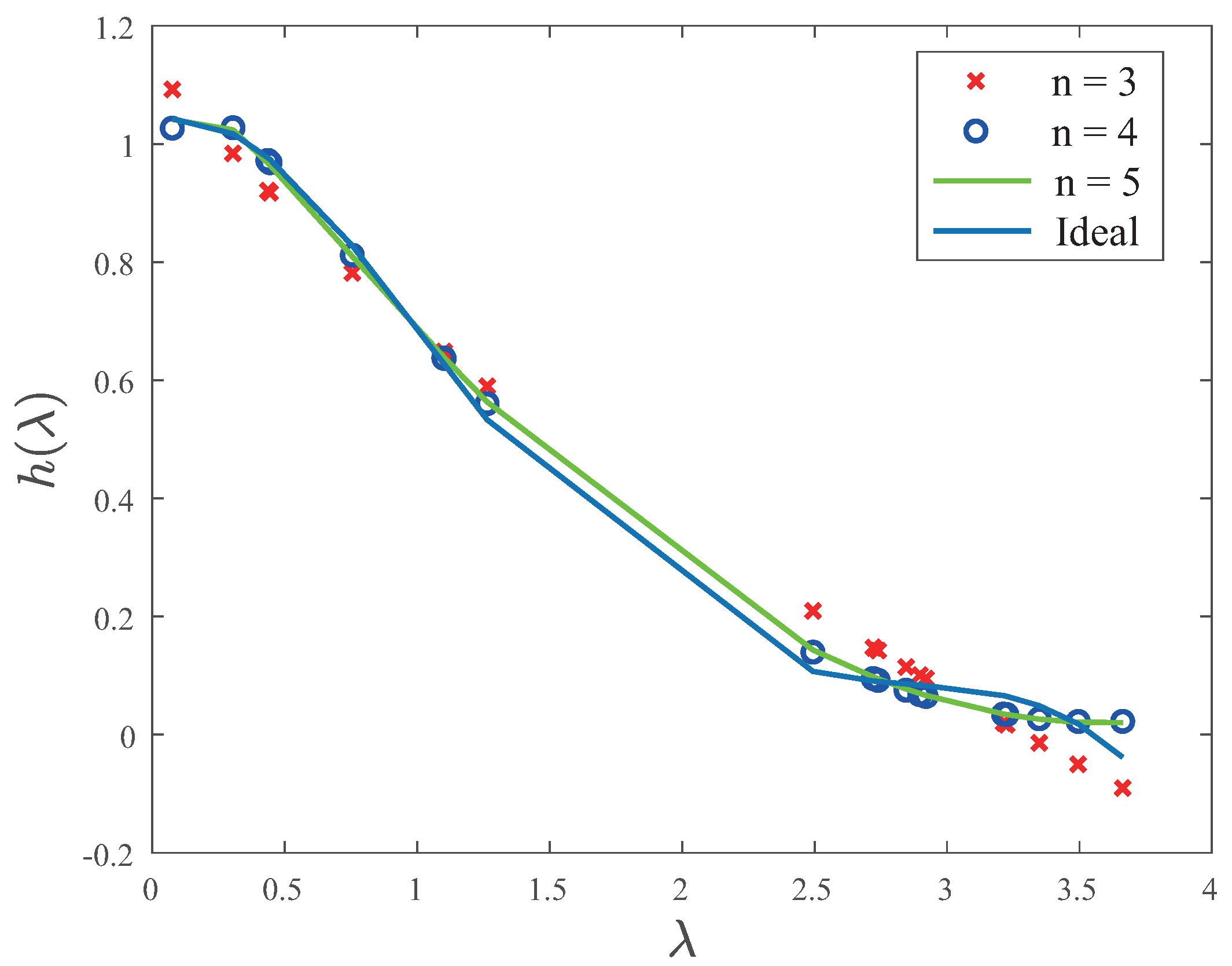
3.3. Filter Performance

In the classical digital filter design, we often use the following specifications: passband frequency ω p , stopband frequency ω s , cut-off frequency ω c , passband attenuation δ p and stopband attenuation δ s . Among these specifications, the cut-off frequency is the frequency point at which the signal power is reduced by half.
Firstly, we will analyze the difference of filter performance between traditional polynomial GF and fractional polynomial GF approximated by GA. In the simulations, we set the population to 500 and let crossover probability P c = 0.95 .
We use GA to design a traditional 9-order polynomial GF to approximate an ideal lowpass FIR GF, where we employ only 4 fractional graph shift operator a 0 I + i = 3 n a i L α i . To put it in another way, the fractional order filter has 4 taps. The result is depicted in Figure 4.
The design specifications is as follow λ p = 0.5 Hz, λ s = 3 /Hz, λ c = 0.75 Hz, δ p = 0.1 and δ s = 0.1 . The maximum difference between the frequency response of GF and FOGF in passband is 0.0308 , while the maximum difference between the frequency response of GF and FOGF in stopband is 0.0538 . It is obvious that the filter performance of 9-order polynomial GF and FOGF with n = 4 is similar.
In Figure 5, we directly use the rational form FOGF to approximate an ideal lowpass filter by GA. We use a 25 nodes swiss-roll graph [45], as shown in Figure 6. The frequency response function is in the following two forms
h 1 ( λ ) = a 0 + a 1 λ α 1 b 0 + b 1 λ β 1 + b 2 λ β 2 ,
and
h 2 ( λ ) = a 0 b 0 + b 1 λ β 1 + b 2 λ β 2 .
The GA parameters remain unchanged. The objective function value of the optimization problem Equation (14) is 0.0264 . In this case, the peak error of passband E p , the peak error of stopband E s and MMSE of the approximated GF E m are shown in Table 1. Moreover, we can get the filter parameters
h 1 ( λ ) = 5.4851 0.7520 λ 5.1940 5.4638 4.3433 λ 6.8011 + 3.5065 λ 7.3959 ,
h 2 ( λ ) = 6.9703 7.3278 4.8155 λ 6.7863 + 4.0030 λ 7.6361 .
As shown in Figure 5, we can get a lowpass filter with a flat passband and an extremely flat stopband, using rational form FOGFs. The traditional filter design methods, like Butterworth or Chebyshev, have a flat passband. But the stopband of them has a lot of ripples. Additionally, we can find that different form of frequency response influences filter response, since filters in Figure 5a,b have different specifications.

3.4. Stability Analysis

When utilizing spectral GFs for learning representations, a necessary condition for transferability in certain tasks is stability. Stability is defined to be the property such that if we add a small perturbation to the input graph, the output of the filter is also perturbed by a small amount [46].
The authors of [46] prove that polynomial GFs are stable with respect to the change in the normalized graph Laplacian matrix. They defined filter distance as
d f = | | h ( L ) h ( L p ) | | 2 .
Similarly, the Laplacian distance is defined as
d L = | | L L p | | 2 .
h ( L ) = k = 0 K h k L ˜ k represents the polynomial GF. L ˜ = L I is the scaled normalized Laplacian of an input graph. L p is the Laplacian of the perturbed graph, which is generated by remove some edges from some nodes’ k-hop neighborhood. A spectral filter is stable if
| | h ( L ) h ( L p ) | | 2 O ( | | L L p | | 2 ) .
We take the simplest polynomial form FOGF h ( L ) = L α as an example. We generate Barabási-Albert graphs with n = 150 nodes and randomly remove each edge with independent probability of 0.5 to give a perturbed graph [47]. The perturbed graph is still connected. We then look at the filter distance for fractional order polynomial GF of order 0.2 , 0.5 and 0.8 . As shown in Figure 7, the filter distance can be seen to scale linearly with the Laplacian distance consistent with Theorem 2 in [46] which states that polynomial filters are linearly stable.

4. Distributed Implementation

Due to the limited communication range of a large network, each node is likely to communicate with its neighbor nodes. Thus, we are interested in the filter’s distributed implementation. Distributed implementations of GFs emerged as a way to deal with the ubiquity of big data applications and to improve the scalability of computation. From [10,26,39], we can learn that distributed methods’ of GFs can reduce communication cost and speed up the calculation. In this section, we only focus on the distributed implementation of polynomial form FOGFs.

4.1. Continued Fraction Equation Method

As discussed in the previous sections, fractional order GSO, which is a fractional order power of the GSO matrix, is the building block of FOGF. To compute a fractional order power of a matrix will require a lot of computation resources. In order to implement an FOGF faster, we need to approximate it by some integer order operators.
In addition, the integer order GSOs, like adjacency matrix W and Laplacian matrix L , can naturally be implemented distributedly. Since, W and L are all localized operators, which allow nodes to exchange only local information [39]. According to Equation (9), the polynomial form FOGF is
H = h 0 I + i = 1 n h i H α i .
Equation (21) is a linear combination of several fractional order GSOs L α i . Our target is to implement L α i distributedly.
Continued fraction expansion (CFE) is a very effective estimation method for function approximation or numerical approximation. It can approximate a function into multiple fractions by means of continuous division. The convergence speed of this method is faster than that of exponential expansion [38,48]. CFE is useful for the expansion of fractional order function [37]. A continued fraction expansion looks like this:
f ( λ ) = λ α = 1 + α ( λ 1 ) 1 + ( 1 α ) ( λ 1 ) 2 + ( 1 + α ) ( λ 1 ) 3 + ( 2 α ) ( λ 1 ) 2 + , α R
This infinite continued fraction representation Equation (22) needs a large number of terms for convergence to a given accuracy. In [49], the authors propose the modified Lentz’s method. It reverses the order of coefficients in CFE. That is, each succeeding continued fraction is made by taking the previous fraction’s reciprocal and adding it to the current coefficient. The algorithm can be terminated until the floating-point precision is achieved. It is one of the best general methods for evaluating continued fractions seems [38].
A polynomial form FOGF is the sum of a few fractional order GSOs. So, we can implement in a parallel way, which means implement each L α i at the same time. The framework of our algorithm is shown in Figure 8.
Since the Lentz’s algorithm is not for matrix functions, we need to convert it into matrix version, which is shown in Algorithm 1. In Algorithm 1, we denote filter parameters a and b according to Equation (22)
a = [ a 0 , a 1 , ] = [ 1 , 1 , 2 , 3 , 2 , 5 , ] ,
b = [ b 1 , b 2 , ] = [ α ( λ 1 ) , ( 1 α ) ( λ 1 ) , ( 1 + α ) ( λ 1 ) , ( 2 α ) ( λ 1 ) , ( 2 + α ) ( λ 1 ) , ] .
Additionally, e p s is the accuracy of approximation, say 10 7 or 10 10 . The parameter ϵ should be less than typical values of e p s · | b j | , say 10 30 . With Algorithm 1, we can compute CFE iteratively according to f ( λ ) = Δ N Δ N 1 Δ 0 , where Δ j is defined in the line 9 of Algorithm 1. In Equation (22), if we replace λ 1 with L I , the fractional order GSO L α i can be implemented iteratively.
For example, if we use 3 terms in CFE of f ( λ ) , the approximation form is as follow
λ α 1 + α ( λ 1 ) 1 + ( 1 α ) ( λ 1 ) 2 + ( 1 + α ) ( λ 1 ) 3 = 1 + α ( 1 + α ) ( λ 1 ) 2 + 6 α ( λ 1 ) ( 4 2 α ) ( λ 1 ) + 6 .
The eigenvalue of L I is λ i 1 , and the function acting on the eigenvalue is equivalent to that acting on the corresponding matrix. As a result, the approximation of the fractional order power of L α is
L α I + [ α ( 1 + α ) ( L I ) 2 + 6 α ( L I ) ] · [ ( 4 2 α ) ( L I ) + 6 I ] 1 .
Algorithm 1: The Matrix Version of Modified Lentz’s Algorithm
  • Require: Filter parameters a , b , accuracy parameters eps, ϵ
  • Ensure: Approximation result F T M
  •  Set F 0 = b 0 I ; if b 0 = 0 , set F 0 = ϵ · I .
  •  Set C 0 = F 0 , D 0 = 0 .
  •  Set j = 0 .
  • repeat
  •   Set D j = b j I + a j D j 1 .
  •   If D j = 0 , set D j = ϵ · I .
  •   Set C j = b j I + a j / C j 1 .
  •   If C j = 0 , set C j = ϵ · I .
  •   Set Δ j = C j D j 1 .
  •   Set F j = Δ j F j 1
  •    j j + 1
  • until  | Δ j I | < e p s
  • T j
After approximating the fractional order GSOs by CFE, we convert the FOGF into an integer order IIR filter. As discussed in the previous section, there are some state-of-the-art methods to implement IIR GFs distributedly [10,11,26,39]. In [26], the authors propose a distributed algorithm called FastIDIIR, which is designed to solve the following optimization problem
arg min y | | By x | | 2 .
It is an inverse FIR module y = B 1 x . Inspired by the gradient descent method, this problem can be solved by the iteration
y ( t + 1 ) = y ( t ) γ ( By ( t ) x ) ,
where γ is the step length parameter of FastIDIIR algorithm.
Adding distributed IIR GF design methods, we propose our own distributed implementation of FOGFs in Algorithm 2. In our algorithm, B = g j ( L ) , y = y j and x = r j ( L ) y j 1 . g j ( L ) and r j ( L ) are all polynomial GFs. For example, at the second iteration,
C 2 = 2 I + ( 1 α ) ( L I ) [ I + α ( L I ) ] 1 ,
D 2 = 2 I + ( 1 α ) ( L I ) .
It is obvious that D 2 y 2 = C 2 y 1 . After simplification, we can get
g 2 ( L ) = [ I + α ( L I ) ] [ 2 I + ( 1 α ) ( L I ) ] ,
r 2 ( L ) = 2 I + ( 1 + α ) ( L I ) .
In summary, we split the FOGF into several fractional order GSOs, and approximate the fractional order GSOs with CFE. In order to compute CFE iteratively, we extend the modified Lentz’s algorithm to the matrix domain. After the previous procedures, we obtain a polynomial form GF and implement it distributedly and iteratively by the FastIDIIR algorithm.
Algorithm 2: Distributed Implementation of Fractional Order GSO Approximated by CFE
  • Require: Input signal x , Step length γ , Iterative times T, Iterative parameters Δ j , j = { 1 , 2 , , T M } .
  • Ensure: Output signal y
  •  Set j = 0 .
  • repeat
  •    y j = Δ j y j 1 .
  •    g j ( L ) y j = r j ( L ) y j 1 .
  •   Let y j ( 0 ) = y j 1 , t = 0 .
  •   repeat
  •     y j ( t + 1 ) = y j ( t ) γ ( g j ( L ) y j ( t ) r j ( L ) y j 1 ) .
  •     t t + 1 .
  •   until  t = T
  •    y j = y j ( T ) .
  •    j j + 1 .
  • until  | | Δ j I | | < e p s
  • y = y j

4.2. Analysis

First, we will analyze the approximation accuracy of CFE. We will keep different number of terms and analyze their approximation accuracy.
As shown in Figure 9, with more terms kept in CFE, the approximation is more accurate. It is explicit that the approximation is precise enough when we keep 8 or 10 terms in CFE. Here, we analyze the approximation error on a sensor graph G with 20 vertices. For simplicity, we employ the simplest fractional order polynomial GF H = L 0.5 . The error function is defined as e = | | h i ( Λ ) h ( Λ ) | | 2 | | h ( Λ | | 2 , where i denotes the number of terms we kept in CFE. We can find that the approximation error of CFE with 8 terms is negligibly small.
Second, we will analyze the performance of Algorithm 2. We use a sensor graph with 16 vertices as an example. As shown in Figure 10, there is almost no error when using the matrix version of the modified Lentz’s algorithm to approximate an FOGF.

5. Conclusions

In this paper, we introduce FOGF design methods as well as their distributed implementation methods. We use GA to solve the optimization problem of filter design and get the filter parameters. Then, we employ CFE and the modified Lentz’s algorithm to approximate the FOGFs by integer order IIR GFs. Due to the limited communication range of some large networks, we employ the FastIDIIR algorithm to implement FOGFs distributedly. Moreover, we analyze the filter performance and approximation error. There are still a lot of problems which need exploration, analysis, and perfection. In the future, we will continue to investigate the theoretical issues of FOGFs.

Author Contributions

Conceptualization, X.Q. and H.F.; Methodology, X.Q.; Software, X.Q.; Validation, X.Q.; Formal Analysis, X.Q.; Investigation, X.Q.; Resources, X.Q.; Data Curation, X.Q.; Writing—Original Draft Preparation, X.Q.; Writing—Review and Editing, X.Q., H.F. and B.H.; Visualization, X.Q.; Supervision, H.F.; Project Administration, B.H.; Funding Acquisition, H.F. and B.H. All authors have read and agreed to the published version of the manuscript.

Funding

This work was supported by the Shanghai Municipal Natural Science Foundation (No. 19ZR1404700), Fudan University-CIOMP Joint Fund (FC2019-003), and 2020 Okawa Foundation Research Grant.

Institutional Review Board Statement

Not applicable.

Informed Consent Statement

Not applicable.

Data Availability Statement

No new data were created or analyzed in this study. Data sharing is not applicable to this article.

Conflicts of Interest

The authors declare no conflict of interest.

References

  1. Shuman, D.I.; Narang, S.K.; Frossard, P.; Ortega, A.; Vandergheynst, P. The Emerging Field of Signal Processing on Graphs: Extending High-dimensional Data Analysis to Networks and Other Irregular Domains. IEEE Signal Process. Mag. 2013, 30, 83–98. [Google Scholar] [CrossRef] [Green Version]
  2. Stankovic, L.; Mandic, D.; Dakovic, M.; Brajovic, M.; Scalzo, B.; Constantinides, T. Graph Signal Processing—Part I: Graphs, Graph Spectra, and Spectral Clustering. arXiv 2019, arXiv:1907.03467v2. [Google Scholar]
  3. Stankovic, L.; Mandic, D.; Dakovic, M.; Brajovic, M.; Scalzo, B.; Constantinides, A.G. Graph Signal Processing—Part II: Processing and Analyzing Signals on Graphs. arXiv 2019, arXiv:1909.10325v1. [Google Scholar]
  4. Stankovic, L.; Mandic, D.; Dakovic, M.; Brajovic, M.; Scalzo, B.; Li, S.; Constantinides, A.G. Graph Signal Processing—Part III: Machine Learning on Graphs, from Graph Topology to Applications. arXiv 2020, arXiv:2001.00426v1. [Google Scholar]
  5. Grady, L.J.; Polimeni, J.R. Discrete Calculus; Springer London: London, UK, 2010. [Google Scholar] [CrossRef]
  6. Krim, H.; Hamza, A.B. Geometric and differential topology of manifolds. In Geometric Methods in Signal and Image Analysis; Cambridge University Press: Cambridge, UK, 2015; pp. 168–237. [Google Scholar] [CrossRef]
  7. Škrjanc, I. Pitch Angle Control of Unmanned Air Vehicle with Uncertain System Parameters. J. Intell. Robot. Syst. 2006, 47, 285–297. [Google Scholar] [CrossRef]
  8. Ma, J.; Huang, W.; Segarra, S.; Ribeiro, A. Diffusion Filtering of Graph Signals and Its Use in Recommendation Systems. In Proceedings of the 2016 IEEE International Conference on Acoustics, Speech and Signal Processing, Shanghai, China, 20–25 March 2016. [Google Scholar] [CrossRef]
  9. Cheung, M.; Shi, J.; Wright, O.; Jiang, L.Y.; Liu, X.; Moura, J.M.F. Graph Signal Processing and Deep Learning: Convolution, Pooling, and Topology. IEEE Signal Process. Mag. 2020, 37, 139–149. [Google Scholar] [CrossRef]
  10. Isufi, E.; Lorenzo, P.D.; Banelli, P.; Leus, G. Distributed Wiener-Based Reconstruction of Graph Signals. In Proceedings of the 2018 IEEE Statistical Signal Processing Workshop, Breisgau, Germany, 1 June 2018; pp. 21–25. [Google Scholar] [CrossRef]
  11. Isufi, E.; Loukas, A.; Simonetto, A.; Leus, G. Autoregressive Moving Average Graph Filtering. IEEE Trans. Signal Process. 2017, 65, 274–288. [Google Scholar] [CrossRef] [Green Version]
  12. Saad, L.B.; Isufi, E.; Beferull-Lozano, B. Graph Filtering with Quantization over Random Time-varying Graphs. In Proceedings of the 2019 IEEE Global Conference on Signal and Information Processing, Ottawa, ON, Canada, 11–14 November 2019. [Google Scholar] [CrossRef]
  13. Gavili, A.; Zhang, X.P. On the Shift Operator, Graph Frequency, and Optimal Filtering in Graph Signal Processing. IEEE Trans. Signal Process. 2017, 65, 6303–6318. [Google Scholar] [CrossRef] [Green Version]
  14. Wang, Y.Q.; Li, B.Z.; Cheng, Q.Y. The fractional Fourier transform on graphs. In Proceedings of the 2017 Asia-Pacific Signal and Information Processing Association Annual Summit and Conference, Kuala Lumpur, Malaysia, 12–15 December 2017. [Google Scholar]
  15. Wang, Y.; Li, B. The Fractional Fourier Transform on Graphs: Sampling and Recovery. In Proceedings of the 2018 14th IEEE International Conference on Signal Processing, Beijing, China, 12–16 August 2018. [Google Scholar]
  16. Sandryhaila, A.; Moura, J.M. Discrete Signal Processing on Graphs: Frequency Analysis. IEEE Trans. Signal Process. 2014, 62, 3042–3054. [Google Scholar] [CrossRef] [Green Version]
  17. Shuman, D.I.; Ricaud, B.; Vandergheynst, P. Vertex-frequency Analysis on Graphs. Appl. Comput. Harmon. Anal. 2016, 40, 260–291. [Google Scholar] [CrossRef]
  18. Belkin, M.; Niyogi, P.; Sindhwani, V. Manifold Regularization: A Geometric Framework for Learning from Labeled and Unlabeled Examples. J. Mach. Learn. Res. 2006, 7, 2399–2434. [Google Scholar]
  19. Girault, B.; Gonçalves, P.; Fleury, E.; Mor, A.S. Semi-supervised Learning for Graph to Signal Mapping: A Graph Signal Wiener Filter Interpretation. In Proceedings of the 2014 IEEE International Conference on Acoustics, Speech and Signal Processing, Florence, Italy, 4–9 May 2014; pp. 1115–1119. [Google Scholar] [CrossRef] [Green Version]
  20. Zhang, F.; Hancock, E.R. Graph Spectral Image Smoothing Using the Heat Kernel. Pattern Recognit. 2008, 41, 3328–3342. [Google Scholar] [CrossRef]
  21. Isufi, E.; Leus, G. Distributed Sparsified Graph Filters for Denoising and Diffusion Tasks. In Proceedings of the 2017 IEEE International Conference on Acoustics, Speech and Signal Processing (ICASSP), New Orleans, LA, USA, 5–9 March 2017; pp. 5865–5869. [Google Scholar]
  22. Tremblay, N.; Puy, G.; Gribonval, R.; Vandergheynst, P. Compressive Spectral Clustering. In Proceedings of The 33rd International Conference on Machine Learning; Balcan, M.F., Weinberger, K.Q., Eds.; PMLR: New York, NY, USA, 2016; Volume 48, pp. 1002–1011. [Google Scholar]
  23. Natali, A.; Coutino, M.; Leus, G. Topology-Aware Joint Graph Filter and Edge Weight Identification for Network Processes. In Proceedings of the 2020 IEEE 30th International Workshop on Machine Learning for Signal Processing, Espoo, Finland, 21–24 September 2020. [Google Scholar] [CrossRef]
  24. Sandryhaila, A.; Moura, J.M.F. Discrete Signal Processing on Graphs. IEEE Trans. Signal Process. 2013, 61, 1644–1656. [Google Scholar] [CrossRef] [Green Version]
  25. Segarra, S.; Marques, A.G.; Ribeiro, A. Optimal Graph-Filter Design and Applications to Distributed Linear Network Operators. IEEE Trans. Signal Process. 2017, 65, 4117–4131. [Google Scholar] [CrossRef]
  26. Shi, X.; Feng, H.; Zhai, M.; Yang, T.; Hu, B. Infinite Impulse Response Graph Filters in Wireless Sensor Networks. IEEE Signal Process. Lett. 2015, 22, 1113–1117. [Google Scholar] [CrossRef]
  27. Shuman, D.I.; Vandergheynst, P.; Kressner, D.; Frossard, P. Distributed Signal Processing via Chebyshev Polynomial Approximation. IEEE Trans. Signal Inf. Process. Netw. 2018, 4, 736–751. [Google Scholar] [CrossRef] [Green Version]
  28. Freeborn, T.; Maundy, B.; Elwakil, A. Field Programmable Analogue Array Implementation of Fractional Step Filters. IET Circ. Devices Syst. 2010, 4, 514. [Google Scholar] [CrossRef]
  29. Radwan, A.; Soliman, A.; Elwakil, A.; Sedeek, A. On the Stability of Linear Systems with Fractional-order Elements. Chaos Solitons Fractals 2009, 40, 2317–2328. [Google Scholar] [CrossRef]
  30. Radwan, A.G.; Elwakil, A.S.; Soliman, A.M. On The Generalization Of Second-order Filters To The Fractional-order Domain. J. Circ. Syst. Comput. 2009, 18, 361–386. [Google Scholar] [CrossRef]
  31. Ali, A.S.; Radwan, A.G.; Soliman, A.M. Fractional Order Butterworth Filter: Active and Passive Realizations. IEEE J. Emerg. Sel. Top. Circ. Syst. 2013, 3, 346–354. [Google Scholar] [CrossRef]
  32. Said, L.A.; Ismail, S.M.; Radwan, A.G.; Madian, A.H.; El-Yazeed, M.F.A.; Soliman, A.M. On the Optimization of Fractional Order Low-pass Filters. Circ. Syst. Signal Process. 2016, 35, 2017–2039. [Google Scholar] [CrossRef]
  33. Shuman, D.I.; Vandergheynst, P.; Frossard, P. Chebyshev Polynomial Approximation for Distributed Signal Processing. In Proceedings of the 2011 International Conference on Distributed Computing in Sensor Systems and Workshops (DCOSS), Barcelona, Spain, 27–29 June 2011. [Google Scholar] [CrossRef] [Green Version]
  34. Oppenheim, A.V. Discrete-time Signal Processing; Pearson Education India: Delhi, India, 1999. [Google Scholar]
  35. Ribeiro, G.B.; Lima, J.B. Deslocamento Fracionário De Sinais Sobre Grafos. In Proceedings of the XXXV Simpósio Brasileiro de Telecomunicaçoes e Processamento de Sinais, São Pedro, Brazil, 3–6 September 2017; pp. 871–875. [Google Scholar]
  36. Riascos, A.P.; Mateos, J.L. Fractional dynamics on networks: Emergence of anomalous diffusion and Lévy flights. Phys. Rev. E 2014, 90. [Google Scholar] [CrossRef] [Green Version]
  37. Euler, L. A Commentary on The Continued Fraction by Which The Illustrious La Grange Has Expressed The Binomial Powers. Available online: http://xxx.lanl.gov/abs/math/0507459v1 (accessed on 22 July 2005).
  38. Press, W.H.; Flannery, B.P.; Teukolsky, S.A.; Vetterling, W.T. Numerical Recipes in C: The Art of Scientific Computing; Cambridge University Press: Cambridge, UK, 1989. [Google Scholar] [CrossRef] [Green Version]
  39. Coutino, M.; Isufi, E.; Leus, G. Advances in Distributed Graph Filtering. IEEE Trans. Signal Process. 2019, 67, 2320–2333. [Google Scholar] [CrossRef] [Green Version]
  40. von Luxburg, U. A Tutorial on Spectral Clustering. Stat. Comput. 2007, 17, 395–416. [Google Scholar] [CrossRef]
  41. Valimaki, V.; Laakso, T. Fractional Delay Digital Filters. In Proceedings of the IEEE International Symposium on Circuits and Systems, Chicago, IL, USA, 3–6 May 1993. [Google Scholar] [CrossRef]
  42. Acharya, A.; Das, S.; Pan, I.; Das, S. Extending the Concept of Analog Butterworth Filter for Fractional Order Systems. Signal Process. 2014, 94, 409–420. [Google Scholar] [CrossRef] [Green Version]
  43. Aittomaki, T.; Leus, G. Graph Filter Design Using Sum-of-squares Representation. In Proceedings of the 2019 27th European Signal Processing Conference (EUSIPCO), A Coruna, Spain, 2–6 September 2019. [Google Scholar]
  44. Goldberg, D.E. Genetic Algorithms In Search, Optimization, and Machine Learning; Addison-Wesley: San Francisco, CA, USA, 1989. [Google Scholar]
  45. Perraudin, N.; Paratte, J.; Shuman, D.; Martin, L.; Kalofolias, V.; Vandergheynst, P.; Hammond, D.K. GSPBOX: A toolbox for signal processing on graphs. arXiv 2014, arXiv:1408.5781v2. [Google Scholar]
  46. Kenlay, H.; Thanou, D.; Dong, X. On The Stability of Polynomial Spectral Graph Filters. In Proceedings of the 2020 IEEE International Conference on Acoustics, Speech and Signal Processing (ICASSP), Barcelona, Spain, 4–8 May 2020; pp. 5350–5354. [Google Scholar] [CrossRef]
  47. Barabási, A.L.; Albert, R. Emergence of Scaling in Random Networks. Science 1999, 286, 509–512. [Google Scholar] [CrossRef] [Green Version]
  48. Vinagre, B.M.; Podlubny, I.; Feliu, V. Some Approximations of Fractional Order Operators Used in Control Theory and Applications. J. Fract. Calc. Appl. Anal. 2000, 3, 231–248. [Google Scholar]
  49. Lentz, W.J. Continued Fraction Calculation of Spherical Bessel Functions. Comput. Phys. 1990, 4, 403. [Google Scholar] [CrossRef]
Figure 1. Two graph Laplacian eigenvectors of a random sensor network graph. The signals’ component values are represented by the blue (positive) and black (negative) bars coming out of the vertices. (a) The constant eigenvector u 1 . (b) The smooth Fiedler vector u 2 .
Electronics 10 00437 g001
Figure 2. Fractional shift of a directed ring graph. The original signal is x ( t ) = sin ( π t 7 ) (a) The graph signal after implementing fractional graph shift is Sx = W 0.5 x . (b) The signal after implementing classical fractional shift is h [ n ] x [ n ] = x [ n 0.5 ] . (c) Difference between the previous 2 signals.
Electronics 10 00437 g002
Figure 3. The influence of numbers of fractional graph shift operators (GSOs) on filter performance.
Electronics 10 00437 g003
Figure 4. A illustration of the polynomial form fractional order graph filters (FOGF) approximated by genetic algorithm (GA).
Electronics 10 00437 g004
Figure 5. A illustration of the rational form FOGF approximated by GA. (a) Frequency response h 1 ( λ ) . (b) Frequency response h 2 ( λ ) .
Electronics 10 00437 g005
Figure 6. The swiss-roll graph with 25 nodes.
Electronics 10 00437 g006
Figure 7. A plot of the Laplacian distance and the filter distance for different fractional order polynomial GFs. The bars indicate the standard deviation of the filter distance.
Electronics 10 00437 g007
Figure 8. The structure of distributed polynomial form FOGF.
Electronics 10 00437 g008
Figure 9. (a) The fractional order function h ( λ ) = λ 0.5 approximated by continued fraction equation (CFE) containing different number of terms. (b) The approximation error of CFE on a sensor graph with 20 vertices.
Electronics 10 00437 g009
Figure 10. The frequency response of H = L 0.5 and an approximation using the proposed algorithm.
Electronics 10 00437 g010
Table 1. Filter performance of rational form FOGFs.
Frequency ResponseJ E p E s E m
h 1 ( λ ) 0.0136 0.0109 0.0163 8.7160 × 10 5
h 2 ( λ ) 0.0264 0.0485 0.0042 0.0010
Publisher’s Note: MDPI stays neutral with regard to jurisdictional claims in published maps and institutional affiliations.

