1. Introduction
It is not easy for engineers to write parallel programming directly, because, when engineers face low-level parallel processing libraries directly, they cannot focus on the design of business logic. In short, humans are accustomed to thinking about one thing at a time, a single process of linear thinking. When humans write programs, they will take human thinking into programs, so the early development of the program can be done by a single core processor. When engineers want to modify the current program into a parallel program, because human are accustomed to linear thinking, engineers need to spend a lot of effort to find the parallel parts of the program and refactor the logic of the program on a large scale. This makes parallel programs difficult to popularize.
On the other hand, according to Amdahl’s law, if there is no part in the program that can be processed in parallel, then, with more cores, the application itself will not get any efficiency gains. However, if half of the sequence processing can be changed to parallel processing, the efficiency will be doubled when the number of cores is not considered. In short, according to Amdahl’s law, there is a limit on the benefits that can be gained by the core increase. This extreme value is limited by the proportion of the sequential processing part of the program. Parallelization is a strategy of constant decoupling. It helps us unravel the interdependence between “when to do” and “what to do,” dividing the original process into smaller, more singular responsibilities, allowing each process to perform operations independently.
The difference between artificial intelligence applications and nonartificial intelligence applications is that artificial intelligence applications have autonomy, learning ability and inference ability. For example, common artificial intelligence applications include car autopilot, dialogue systems and robots. How to design a framework that fits the application of artificial intelligence is an important issue. On the other hand, the software framework of artificial intelligence applications needs to maximize the performance of the CPU in order to make its application truly effective. On the CPU side, the proportion of software parallelism is insufficient, which is the main reason why CPU cannot be effectively utilized at present. For this reason, this article proposes a software framework called CellS, and the purpose of this framework is to provide solutions for the following three issues:
How to speed up the response time on a resources-constrained mobile system?
How to establish an integration framework suitable for artificial intelligence applications?
How to refactor the software flow with a small cost?
In recent years, artificial intelligence has flourished, especially in pattern recognition, speech recognition and nature language processing. In terms of pattern recognition, for video data, there are traffic signs used to identify symbols and texts [
1]. In terms of identifying expression data, Jianzhu Guo also provides iCV-MEFED datasets with 50 types of composite emotion tags, allowing people to deepen the study of facial expression recognition [
2]. In terms of speech recognition, Yan Zhao reduced the influence of noising and reverberation on speech recognition [
3]. On the other hand, the study of speech is not only used for speech recognition but also for speech emotion recognition, for example, using semisupervised automatic encoders to improve speech emotion recognition [
4]. In terms of nature language processing, there are also many studies, such as improvement of segmentation and pos tagging [
5], sentence autocompletion [
6], neural machine translation [
7], natural language generation, [
8] and question generation [
9]. Nature language processing is also used in different fields, such as food diary methods for preventing and treating obesity [
10] and analyzing clinical records and predicting readmissions [
11].
In computer science, application refers to the implementation of software and hardware to achieve a certain purpose. Similarly, artificial intelligence application refers to the implementation of hardware and software with artificial intelligence features to achieve a certain purpose. From the current research on artificial intelligence application [
12,
13,
14,
15,
16,
17], it can be concluded that an artificial intelligence application basically has three main features: (1) autonomy, (2) learning ability, and (3) reasoning ability. Autonomy represents an application with its life cycle, and when the application is launched, it can autonomously perceive the external environment and react. Learning ability represents that the application can obtain and use rules of thumb based on past data. Reasoning ability represents that an application can infer further information or next actions based on current conditions. Taking AlphaGo as an example, its three characteristics are (1) autonomously playing chess without human interference; (2) using value network and policy network, two deep learning techniques; and (3) using Monte Carlo tree search to judge the difference of the chessboard situation and infer the current move. Based on these three characteristics, this study establishes the CellS software architecture to integrate artificial intelligence applications. The design principles, component design and life cycle of CellS are further explained in
Section 3.
In the multicore CPU, many studies are trying to maximize the efficiency of the CPU to improve the efficiency of the algorithm. Andrés solved the problem of probabilistic graphical Model and datasets of the same size using Java 8 parallel processing [
18]. On the other hand, the combination of CPU and GPU can improve the algorithm efficiency. For example, Neng Hou uses a combination of multicore CPUs and multicore GPUs to effectively reduce the run time of parallel genetic algorithms for dispersion correction for soft and hard partitions [
19]. As can be seen from the above, the combination of the CPU and the GPU is very important. To maximize the efficiency of multicore CPUs, the parallel framework is indispensable in terms of software. There are many types of parallel frameworks, three common categories, as follows:
Actor Model: In the actor model, an actor is a programmatic abstraction that is considered the basic unit of parallel computing. When an actor receives a message, it can make some decisions, build more actors, send more messages, and decide how to respond to the next message. The common actor model implementations are Akka, Actor4j, SObjectizer, and Orleans.
Dataflow Programming: Dataflow programming emphasizes the movement of data and model programs as a series of connections. This programming hasclearly defined input and output operations. As long as all inputs are valid, the operation will run. Therefore, dataflow programming is essentially parallel and works well in large distributed systems. Common dataflow programming implementations are LabVIEW and VHDL.
Multithreading: Multithreading is a broad programming and execution model that allows multiple threads to exist in a single process. These threads share the resources of the process and can be executed independently. Multithreading provides developers with an abstraction of parallel execution. Common programming languages with multithreading are Java, C++ and Python.
The framework proposed by this paper combines the concepts of actor model and dataflow programming and is constructed using multithreading in Java. Autonomy is one of the characteristics of artificial intelligence applications, and, in the past research, the software agent clearly has this feature. Among the many software agents, the belief–desire–intention (BDI) agent is a limited rational software agent with specific psychological attitudes (i.e., beliefs, desires, and intentions). The BDI agent uses a belief–desire–intention software model (BDI for short). Belief represents the state of the information that the software agent feels (i.e., the perception of the external environment). Desire represents the motivational state of the software agent, which represents the goal that the software agent wants to accomplish. Intention is the willingness of the software agent to promise to some extent, which means that the agent has begun to execute the plan for the goal. The BDI agent is a software model developed for building an intelligent agent that provides a mechanism for separating the selection of a plan from the execution of a plan. Common BDI frameworks are JAM [
20], Jason [
21], JadeX [
22], and BDI4JADE [
23]. We will compare these BDI frameworks in
Section 4.5.
2. Proposed Framework
In this paper, we focus on interactivity and performance issues and then propose the solution, i.e., the CellS framework. The design principle of the CellS framework comes from two aspects: (1) the cell theory and (2) the belief–desire–intention software model (BDI). The theory determines the core thinking of the framework, and the BDI determines the activity mode of the framework. Next, we will give an overview for the framework.
2.1. Overview
The core thinking of the CellS framework is inspired by the cell theory. The human brain contains 86 billion cells, and the cooperation of these cells forms the human mind. Sense cells collect environmental messages and trigger the corresponding cells to work together and, ultimately, output internal messages to motor cells. Receptors, also known as receivers, are a biochemical concept that refers to a class of molecules that can transmit extracellular signals and produce specific effects in cells. A receptor can sense extracellular signals by binding to specific ligands. A ligand refers to a substance that can bind to the receptor to produce a certain physiological effect. For example, enzymes, RNA, and ribosome are all receptors, and extracellular ligands exert their effects by combining with these receptors. When the cell reacts to an environmental stimulus, it triggers local cells instead of a single cell, and all triggered cells run simultaneously. In biology, cell theory is a generally accepted scientific theory that living cells are made up of cells, and cells are the basic unit of all organisms. The description of the cell theory is as follows:
All living organisms are composed of one or more cells,
The cell is the basic unit of structure and organization in organisms, and
Cells arise from pre-existing cells.
From the perspective of cell theory, we can see that all living things are made up of cells, which are the basic structural units. A cell can do its own work, and a group of cells can also work together to complete a task. All cells process their own tasks at the same time. We were inspired by the cell theory to create a software framework, the CellS framework. The core thinking of the framework is described as follows:
All software applications built by the CellS framework consist of more than one cell,
The cell is the basic unit of structure and organization in the CellS framework, and
The cell instances come from preexisting cell classes.
Since the framework is inspired by the cell theory, the cell component in the framework is also expressed by terms in biology. The CellS framework consists of four components: (1) ligand, (2) sensory cell (SCell), (3) brain cell (BCell), and (4) motor cell (MCell), details of which are described in
Section 2.3.
The BDI model is a software model developed for programming intelligent agents, and the BDI model implements Michael Bratman’s theory of human practical reasoning [
24]. The BDI model is characterized by the implementation of the agent’s beliefs, desires, and intentions and provides a mechanism for separating the selection of the plan and the execution of the plan. The BDI model inspired us to design the behavior of each cell in the CellS framework. The autonomous behavior of the cell consists of three parts: (1) decide whether to process the information (or features) from a ligand, (2) choose a plan (or a method) to use to process the information of this ligand, and (3) define the specific implementation content of this plan and execute it. In this framework, the autonomous behavior of a cell forms its life cycle, which we will detail in the next section.
2.2. The Operation of the Framework
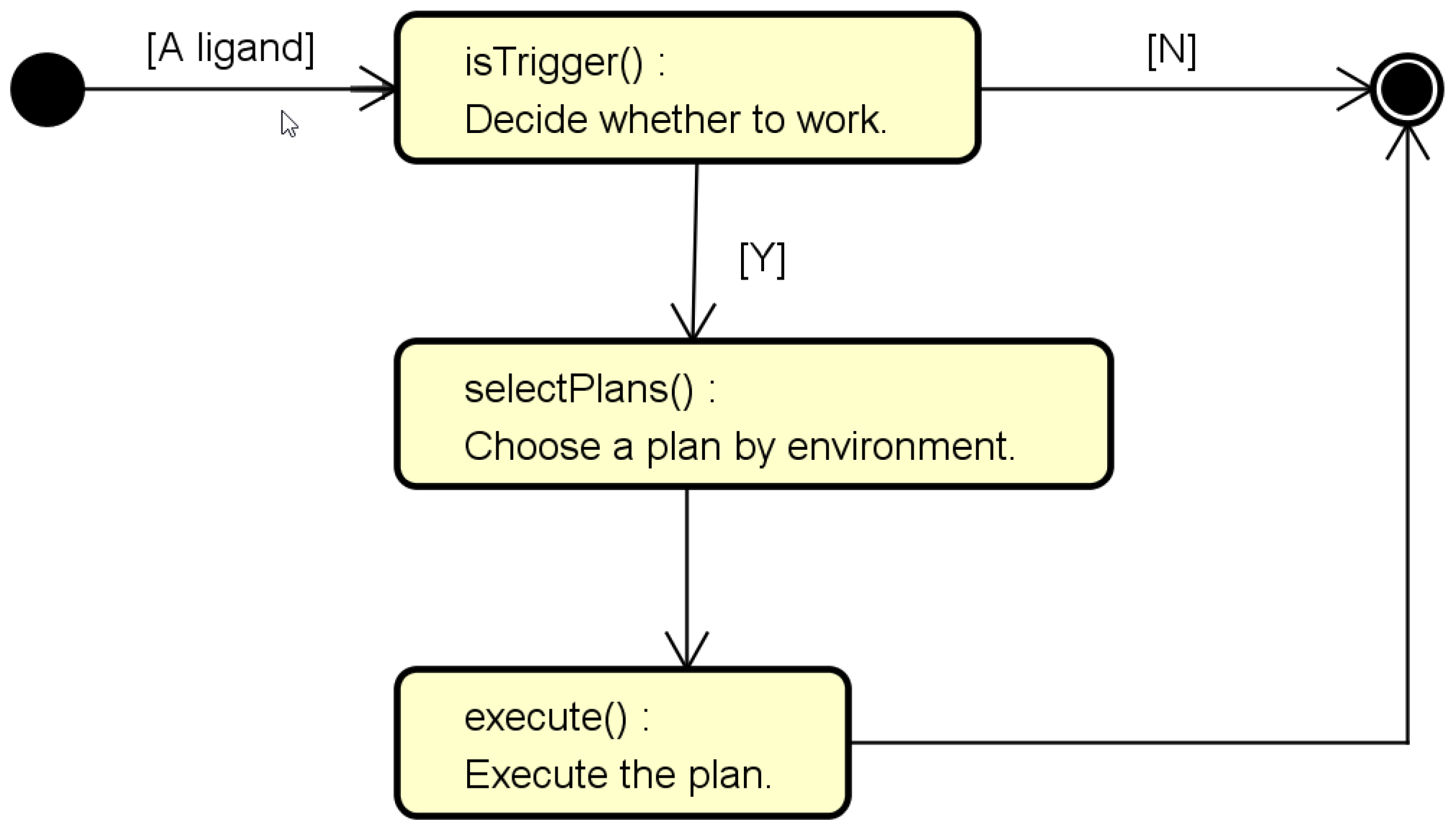
In order to understand the operation of the framework, we start with the life cycle of the smallest unit (i.e., cell) in this framework. In simple terms, a cell is an information generator, which generates new information based on the received internal information of the ligand. Each cell in CellS has three parts in its life cycle: (1) isTrigger, (2) selectPlans, and (3) execute. When a cell perceives a certain ligand, it will decide whether to process the ligand according to the internal information of that ligand. The cell that wants to process the ligand will select the appropriate plan to process it according to the content of information in the ligand. Finally, this cell will execute the selected plan and generate new information. Finally, this cell will execute the selected plan and generate new information, as shown in
Figure 1.
Figure 1 shows the view of a single cell. However, in each CellS, all cells are executed at the same time; that is, the life cycle of a CellS refers to the life cycle of all cells within it for the current ligand. More complicated, in a single life cycle of CellS, there may be more than one ligand; that is, each cell will analyze the information of each ligand and then decide which ligands to deal with. Each cell can complete a task on its own and can also work with other cells to complete a task. When a task is simple, a cell can complete the task on its own, and when the task is very complex, a group of cells can work together to complete a complex task. For complex tasks, the advantage of those cells working together is that they increase efficiency, because each cell is executed together at the same point in time. All cells are independent of each other, but cells that are independent of each other sometimes act together for the same information, because they all believe that they should act under this information. A simple example is shown in
Figure 2. In this example, the CellS contains 15 cells; when the CellS sense a certain ligand, 6 of the cells are triggered. In other words, as shown in
Figure 2b, some cells with solid dots, cell 1, cell 3, cell 5, cell 7, cell 12, and cell 14, represent that those cells are executed together for a certain ligand.
In
Figure 2, all cells are not classified, but there are three types of cells in the CellS: (1) SCell, (2) BCell, and (3) MCell. In
Section 2.3, we will introduce them further, as in this section we focus on the life cycle. The life cycle design of CellS uses the methodology of MIAT Lab [
25]. In this methodology, the design approach uses the Grafcet. The Grafcet is derived from the Petri net mathematical model and is a discrete event dynamic system suitable for describing asynchronous, parallel computer system models.
Figure 3 is a CellS with six cells, containing two SCells, two BCells, and two MCells.
Figure 3a–h are fragments of the continuous execution of a CellS, showing the design of the life cycle: (1) During a single life cycle of the CellS, cells are triggered at the same time, but each cell itself decides whether to execute it or not. (2) All SCells always execute in each life cycle. (3) All cells may be executed at the same time, and the greater the number of cells executed at the same time, the higher the utilization of the multicore CPU. (4) When all cells are finished in a single life cycle, the life cycle ends and begins to run the next life cycle. From the life cycle design of the CellS, we found that the life cycle using the CellS is shorter than the life cycle without using the CellS. Such a life cycle design can take full advantage of the multicore CPU and achieve a good performance. Because of this, when designing a CellS-based application, you need to understand and focus on the data flow of an application, which is say, design precedes development.
2.3. The Implementation Details of the Framework
In this section, we will use the class diagrams of Unified Modeling Language (UML) to describe our framework in detail using two views of different granule (single-cell view and single-anima view), and at the end of this section, we will introduce the communication among anima. In the framework proposed by this paper, there are five important components, including anima, deliberation, cell, plan, and ligand. This framework has five naming rules: (1) an interface starts with “I,” (2) an abstract class starts with “A,” (3) a class extending “ACell” ends with “Cell,” (4) a class extending “APlan” ends with “Plan,” and (5) a class extending “ALigand” ends with “Ligand”. For example, in
Figure 4, “IPlan” is the interface of Plan; “APlan” is the abstract class of Plan; “BCell” extends “ACell”; “EmptyPlan” extends “APlan”; “Ligand” extends “ALigand”.
Figure 4 and
Figure 5 are class diagrams with attributes omitted.
2.3.1. Single Cell View
In the cell’s point of view, a cell receives a ligand from the outside world, decides whether to run and which plans to be executed based on its information, and then completes its tasks to end its life cycle. In this framework, a cell is the smallest unit of operation, and all cells implement ICell and extend ACell. From the ICell in
Figure 4, we can understand that each cell mainly performs three operations: isTrigger() and selectPlans(), and each cell is completed by the exe() of ACell. This method based on different messages in the ligand selects and plans to execute and then ends this round. Each plan has two functions: use selectFeedback() to transfer the information of the ligand and use execute() to complete its task. On the other hand, the ligand not only determines how to select plans but also determines which cells are triggered.
There are three kinds of cells: BCell, SCell, and MCell. First, SCell will sense the information of the external environment and turn it into the beliefs of this framework. Next, BCell will decide whether to execute or not, and the BCell that decides to execute will select a plan to execute according to the information. Finally, the results of the plan execution will generate new information or cause MCell to have an impact on the external environment. The ligand is responsible for transmitting information within the CellS architecture, including beliefs and new information generated by BCell. The information generated by the cell will be stored in the ligand, and then the ligand will pass the information to other cells. The main methods of the ligand are getReference() and getCollection(), and its data structure is Map. The getReference() method in the ligand stores the information generated by the previous cell for the current cell reference, and the getCollection() method in the ligand is used to collect the information generated by the current cell. Because the cell information is transmitted by the ligand, there are many different ligands in this framework.
In the BDI model, the desire represents the motivation of the system, that is, the goal or state that the system wants to achieve; the intention indicates the goal that the system promises to accomplish. In this framework, the desire and the intention represent the two states of cell: the desire is the state in which cell is not executed, and the intention is the state in which cell decides to execute. A cell contains two main methods, isTrigger() and selectPlan(); these two methods are decoupling strategies in our framework, which are described as follows:
isTrigger(): Defines the cell auto-execution condition. Each ligand encapsulates beliefs and the information generated by cells; each cell will decide whether to execute according to the ligand. When different cells have the same trigger condition, they will execute autonomously at the same time. This method mainly solves the problem of decoupling in the parallelization software, “when to do”.
selectPlan(): Defines the condition that the cell selects the plan, that is, selects an actual behavior to complete the intention. Each cell will select a different plan depending on the information in the ligand. This behavior forms the concept of BDI, that is, take different actions for different purposes. This method mainly solves the other problem of decoupling in the parallelization software, “what to do”.
There are three cells, which extend from ACell class, as follows:
BCell: This cell forms the main part of the cell in the framework, which uses the ligand to reference or collect information. Since the ACell implements the ICell interface and the Runnable interface, the class that inherits the BCell has threading capabilities and needs to implement the isTrigger() and selectPlan() methods. The main ability of the BCell in the CellS architecture is to generate new information.
SCell: This cell is a specialized cell; that is, the cell continuously perceives information about the external environment. The SCell differs from the BCell, in that it implements the isTrigger() method; that is, the response of the isTrigger() method is always true. For the class that inherits from SCell, the engineer only needs to implement the selectPlan() method. In SCell, the implementation of isTrigger() reflects the behavior of the framework to detect external environmental information at any time.
MCell: This cell needs to have an impact on the external environment. In biology, an effector is a muscle, gland, or organ that responds to a stimulus, especially a nerve impulse. In the framework, the effector refers to a component that can affect the external environment, and MCell refers to the cell that can control the effector. Each MCell can take all the effectors in the framework and use its plan to manipulate them.
The plan represents a series of activities in the BDI model and is an act of achieving intention. In the BDI model, the goal represents the end result of a series of intentions. In framework, each cell selects different plan executions according to different situations, and the plan represents the specific behavior of reaching the intention, that is, how to complete the task of the intention. Each plan uses the information of the ligand to perform its tasks specifically. IPlan is the interface of the plan, and APlan is the abstract class of the plan. The plan contains three methods: (1) execute(), (2) selectFeedback(), and (3) selectEffect(); the capabilities of these three methods are (1) complete the intent task, (2) generate the ligand, and (3) establish cross-lifecycle actions in the framework.
execute(): This method is the main part of the plan in the framework. The responsibility of this method is to complete the task of the intention; different cells (SCell, BCell, and MCell) have different tasks. For SCell, this method defines how information is obtained from the external environment. For BCell, this method uses the information of the ligand and generates new information to be stored in the ligand. For MCell, this method controls the effector to interact with the outside world. When the engineer creates a class that extends the AExecutionPlan, he or she only needs to focus on achieving the intention, which is the implementation of this method.
selectFeedback(): This method in the plan is to select different feedbacks under different conditions. Each feedback will refer to the old ligand to generate a new ligand, and the ligand will induce the execution of the cell in the framework. FeedbackPlanFactory is a factory method pattern design that uses the InnerFeedbackPlan to encapsulate the feedback and create a new plan for the cell. The ligand generated by the feedback affects all cells in a life cycle of the framework.
selectEffect(): This method in the plan is to select different effects under different conditions. Each effect has a cross-lifecycle impact on the framework. For example, suppose the task of an effect is to play music; the effect will determine when it starts and when it ends, and it does not affect the lifecycle of the framework.
2.3.2. Single Anima View
Figure 5 shows the class diagram of this framework from the perspective of anima. In this framework, anima is composed of more than one cell, it has a goal that is eager to satisfy, and it is the basic unit to finish a mission. Anima uses IDeliberation to trigger the behavior of cells; that is, every time it performs thinking(), cells will execute their life cycle one time. IDeliberation contains three main methods: in order, triggerCells(), runCells(), and Desires2Intentions(). The tasks of the first two methods are as their names imply, and the task of the third method is to convert the desire cell into an intention cell. The information of the ligand is memorized by the anima. When a cell is triggered, the cell will retrieve the information of the required ligand from the anima as the basis for action. Anima also can interact with the outside world to obtain information by using SCell and transform it into internal ligand and react to the outside world by using MCell. A system constructed by CellS is constructed by more than one anima, and the smallest unit of CellS system to satisfy the mission is anima.
Each anima can create more than one IPool to provide other anima services.
Figure 6a is a class diagram of IPool and its related classes. As can be seen from this figure, IPool provides two data structures, Map and List, for data exchange.
Figure 6b is a schematic diagram among anima and IPools. It can be seen from this figure that an IPool of anima can provide service to several anima. For example, IPool 2 can provide the service of Anima 2 for Anima 1 and Anima 3 to use.
2.4. Developer Interface for the Framework
This section describes how to use this framework for development. This framework is based on Java, so the general process only needs to follow the Java development process. First, introduce a noun that is stage. In this framework, all cells triggered by a ligand (here the triggered cell refers to the cell whose isTrigger() returns true), within the period from when they are triggered to the end of them, are called a stage. The difference from general Java development includes four steps: (1) stage analysis, (2) anima assembly, (3) cell implementation, and (4) plan implementation. The details are as follows:
Stage analysis: The purpose of this step is to identify the dependence of the data and design ligands of different stages. The data dependency here refers to the sequence of generating a series of middle data before the program generates a result. After this analysis, we will find that some programs are dependent on the same group of data, and each program is independent of each other. This group of independent programs will become the cells in the third step and be in the same stage. Finally, a ligand is created to represent this stage. In this step, more than one stage will be established as the main architecture of the system.
Anima assembly: In the previous step, the stage we produced may contain several loop structures. If the stage contains a loop structure, cut off the loop structure and generate a new anima. If there are n loop structures in the structure, the entire system will have n+1 anima. Finally, use IPool to combine anima.
Cell implementation: In this step, we implement the previously analyzed cells. Most cells will extend BCell. If you want to receive external information or react to the outside world, then extend SCell and MCell.
Plan implementation: Each cell may behave differently at different values of the same variable. In this step, we implement different plans based on different behaviors. In general, the plans we implement will extend AExecutionPlan, but if you want to generate a plan that transmits the ligand, you can use FeedbackPlanFactory.
We assume that a simple dialogue system is created through sequential programming to illustrate our framework concept. The system consists of two main functions, one for chatting (Chat) and the other for answering the question (QA), as shown in
Figure 7. QA includes finding answers from ontology that we have created and finding answers from the web. This involves searching and retrieving answers from the web if we cannot find answer from ontology. Before Chat and QA, the system will use the Stanford parser to extract the part of speech (POS) and named entity recognizer (NER). In addition, we will extract the abstract notion (Notion) of each word. The next step is to find the purpose of the sentence, the relationship between attributes in the sentence, inequality conditions, and positional relationship. Using the above information for Chat or QA is as shown in
Figure 7a. The module in
Figure 7a is equivalent to the plan in
Figure 7b (e.g., Purpose).
Now we describe how to convert the dialog system to the application of the CellS framework. From
Figure 7a, we can find the data dependencies between plans. The processing of POS, NER, Notion, and purpose is based solely on the original sentence. The property relations, inequality relations, and the positional relationship are dependent on the information obtained from the previous sentence. We know that plans that depend on the same data can be executed together at the same time. Based on this idea, we execute plans which rely on the same information at the same time, as shown in
Figure 7b. On the other hand, in the cell framework, the BCell can choose different plans according to different situations. Notion BCell uses a different plan in different languages, such as Chinese or English. In the same purpose to adopt different strategies, the CellS framework has good scalability. Finally, information generated by each life cycle and information sensed by sense cells is encapsulated into the ligand, providing the next life cycle to trigger BCells. Under this analog conversion, we converted the original program into the CellS format. In the CellS format, the program has parallel capabilities, but the developer did not write any parallel programs. Next, we use a simple addition example to illustrate how to create a simple cell.
This framework provides a mechanism to separate the behavior of selecting a plan (i.e., implementing a cell) from the behavior of executing a plan (i.e., implementing a plan).
Figure 8 shows an addition example using cell (i.e., SumBCell). When a developer is developing a cell, he or she has to implement two tasks: (1) determine the cell’s trigger conditions (i.e., isTrigger()) and (2) determine the conditions for selecting a plan (i.e., selectPlans()). Taking
Figure 8 as an example, the trigger condition for SumBCell is whether the message of operands is included in SimpleLigand; the condition for SumBCell to select the plan is based on the size of operands.
Figure 9 shows the execution content of the plan selected under different operands sizes. We can find that the execution content of Sum1Plan is only valid when the operands size is 1; that is to say, the execution content of the plan will be determined according to the characteristics of the information in ligand. The mechanism provided by this framework can handle the constantly changing and the evolving nature of software.
2.5. Automated Tests of the Framework
The system established by this framework is composed of cells, and each cell can be independently tested. From the viewpoint of unit test, every cell is testable, because it has the conditions to be triggered and generates certain information (that is, clear input and output). From the viewpoint of integration test, if the input and output in the system are all correct, the preliminary integration test is completed. In most systems, that means the entire integration test is completed. We use the general unit testing framework JUnit to demonstrate an example of unit test for a cell.
Figure 10 shows how to test the SumBCell developed in the previous section. This is a simple test to illustrate how to test multiple plans in a cell. First, we prepare to test the required anima, ICell, and ILigand and perform the initialization actions in the setup method. Then, we put the test case into the ligand and use BDICommon.getTestResult() to test. Finally, the actual results and expected results are evaluated to complete the unit test of SumBCell. Since the system established by this framework is composed of cells, and each cell can be tested in this way, the preliminary integration test of the system will also be completed when the unit test of each cell is completed.
3. Materials, Methods, Result, and Analysis
Human–computer interaction (HCI) is an important issue for all software systems, including AI systems. In HCI, the reaction time of the system is the key factor for the effectiveness of the system. In this section, we conducted two experiments to observe the effect of CellS framework on reaction time. The first experiment was a hypothetical experiment. In the experiment, we assumed that the components of the dialogue system had the same execution time and were executed in the sequential system, the concurrent system, and the CellS framework. The second experiment was an experiment of a software dialogue system established by the CellS framework. In the experiment, we deployed the system on mobile devices with different number of cores and observed its execution. The boxplot was invented in 1977 by the American statistician John Tukey. It consists of five numerical points: minimum, lower quartile (Q1), median, upper quartile, maximum, and mean. According to our experimental results, we used the boxplot for statistical analysis of the data, which could effectively help us identify the characteristics of the data. Experiments show that the programming method of CellS had a faster reaction time than sequential and concurrent programming.
3.1. Hypothetical Experiment
The purpose of this experiment was to observe the changes in reaction time and CPU usage under different programming methods, as well as to find the limits of the CellS framework by the execution time of the components. The next section will explain the detailed settings of the experiment.
3.1.1. Methods and Materials
We used the example of a hypothetical dialogue system in
Figure 7 as the blueprint for the flow design of this experiment.
Figure 11 shows the different programming methods to build the system flow. In this experiment, we assumed that 10 components had the same execution time, and the completion of a flow would execute 10 components (this represents a dialogue system’s response to the user). When 10 system flows were completed, we recorded the response time (1 round). In addition, we observed the changes in different programming methods when the component execution time was 1 millisecond, 3 milliseconds, 10 milliseconds, and 100 milliseconds. Finally, we recorded the CPU usage every second and observe its changes.
In terms of CPU usage, we used the following two commands to get CPU-related information, including user, nice, system, idle, iowai, irq, softirq, utime, stime, cutime, and cstime [
26]:
Then, we used the preceding and following time points (T1 and T2) and the following formula to calculate the CPU usage:
Total Jiffies (TJ) = user + nice + system + idle + iowait + irq + softirq
Process Jiffies (PJ) = utime + stime + cutime + cstime
CPU Usage = [(PJ of T2) − (PJ of T2)]/[(TJ of T2) − (TJ of T2)]
Finally, the CPU information of the Android device is shown in
Figure 12.
3.1.2. Experimental Result and Statistical Analysis
Figure 13 and
Figure 14 show the time and CPU usage required to execute 100 workflows using three programming methods. From
Figure 13a, we can find that, when each task flow is 1 millisecond, no acceleration effect occurs in concurrent programming and CellS programming. However, once the task flow is greater than or equal to 3 milliseconds, concurrent programming and CellS programming begins to produce acceleration effects, and the effect of CellS programming is more significant than that of concurrent programming, as shown in
Figure 13b–d. In
Figure 14, we clearly find that CellS programming can increase CPU usage and decrease the reaction time of the program. The exception is that when the task flow is less than 3 milliseconds, CellS cannot play an acceleration effect. Therefore, the limitation of using CellS is that the task flow (i.e., plan) must be greater than or equal to 3 milliseconds.
3.2. Experiment for AI-Enabled Dialogue Application on Resources-Constrained Mobile System
In this experiment, we observed the changes in throughput and speedup of CPUs with different numbers of cores to test the performance of the CellS framework. On the hardware side, this experiment used two multicore CPUs, including the Qualcomm Snapdragon MSM8916 410 and the Qualcomm Snapdragon 810. We implemented an artificial intelligence application that could respond to a user’s basic question or to talk (i.e., a dialogue system), as shown in
Figure 15. We used two ways to build this application: one used the CellS framework, and the other used sequential programming.
3.2.1. Methods and Materials
To evaluate the performance of the CellS framework in different multicore CPU, we experimented to compare the execution time of the Qualcomm Snapdragon 810 with the execution time of the Qualcomm Snapdragon MSM8916 410. The configuration of the evaluation platform is shown in
Table 1. The Qualcomm Snapdragon 810 had 8 cores, and each core had a clock frequency of 1.5 GHz. The Qualcomm Snapdragon MSM8916 410 had 4 cores with a clock frequency of 1.2 GHz per core. In this experiment, each round included 100 system flows. Each system flow represented a user’s question or a command. The calculation formula for throughput is as follows:
On the other hand, we evaluated the speedup based on execution time, and the formula for the speedup is as follows:
3.2.2. Experimental Result and Statistical Analysis
Figure 16 shows the experimental results of throughput for 4-core CPU and 8-core CPU in different programming methods.
Figure 17 shows the experimental results of the speedup of 4-core CPU and 8-core CPU, with the CellS framework relative to sequential programming. In the next section, we will analyze and discuss the experimental results and extended topics of this section.
Figure 18 shows the experimental results of throughput for 4-core CPU and 8-core CPU in the same programming method, CellS.
5. Conclusions and Future Work
In this study, we developed a framework called CellS, inspired by the cell theory. The CellS is a light-weight framework that does not have to depend on other systems; it is easy to integrate with other systems, and it can be used within the resources-constrained mobile system. This framework uses a pure programming language (i.e., Java), no additional script or schema, and is easy-to-use for engineers. The CellS framework can increase the utilization of multicore CPUs and increase the performance of applications built by it. When software engineers use this framework, they can easily focus on business logic development. It is a fast and intuitive development framework, and it has a good dynamic and extensibility, due to being combined with the parallel computing and the heuristics of the cell theory. The results of the experiment can prove that this framework has the advantages of high performance but also point out the required precautions when using of CellS to build the system.
In the introduction, we mentioned that the CellS framework proposes solutions for three issues. In terms of speeding up the response time, from the statistical analysis results of the experiment, we can see that when the execution time of the plan was greater than or equal to 3 milliseconds, CellS had a good acceleration effect, and the maximum acceleration was 1.94 times. In terms of AI software integration, as described in
Section 4.6, CellS effectively utilizes Java’s reflection mechanism to implement a framework that is easy to integrate software. In terms of refactoring the software process, the layering of cell layer and plan layer (that is, the separation of decision-making and implementation methods) reduced the cost of refactoring the software process, as described in
Section 4.6. Typical software is passive, but in the AI world, software needs to be active, spontaneous, and self-managing. Accordingly, this framework inherits the results of the past advanced BDI research, and further accelerates its response time, reduces its reconfiguration software process cost, and makes it an easy-to-integrate architecture.
In terms of future prospects, we have the following two aspects:
For the first aspect, we plan to use this software framework in more applications. Although this framework has won the ranking in the competition of the Ministry of Science and Technology of Taiwan in the past, and it has been proven in the question-and-answer system and the task-based dialogue system. Under the current AI trend, it should be possible to use this framework to complete more AI applications and achieve mutual achievements.
The second aspect is that we plan to extend this software design to more different languages. The software design concept of this framework is the integration of parallel computing, reflection mechanism, and BDI. As long as the programming language meets these characteristics, a CellS framework can be built on it to be applied to its exclusive machine.


