Article

Arbitrary Configurable 20-Channel Coincidence Counting Unit for Multi-Qubit Quantum Experiment

1
Center for Quantum Information, Korea Institute of Science and Technology, Seoul 02792, Korea
2
Division of Nano & Information Technology, Korea Institute of Science and Technology School, Korea University of Science and Technology, Seoul 02792, Korea
*
Author to whom correspondence should be addressed.
Electronics 2021, 10(5), 569; https://doi.org/10.3390/electronics10050569
Submission received: 25 January 2021 / Revised: 23 February 2021 / Accepted: 24 February 2021 / Published: 28 February 2021
(This article belongs to the Special Issue Microprocessor and Integrated Circuits)

Abstract

:
This paper presents a 20-channel coincidence counting unit (CCU) using a low-end field-programmable gate array (FPGA). The architecture of the CCU can be configured arbitrarily to measure from twofold to twentyfold coincidence counts thanks to a multifold controllable architecture, which can be easily manipulated by a graphical user interface (GUI) program. In addition, it provides up to 20 of each input signal count simultaneously. The experimental results show twentyfold coincidence counts with the resolution occurring in a less than 0.5 ns coincidence window. This CCU has appropriate characteristics for various quantum optics experiments using multi-photon qubits.

1. Introduction

A coincidence counting unit (CCU) is a module that can count the coincidences of two or more electrical inputs. CCUs are widely used in experiments on quantum optics [1,2,3,4,5,6,7,8,9,10], quantum communication [11,12,13,14,15], and the measurement of radioactive isotopes, among other applications [16]. Due to the advancement of techniques in all fields, there is increasing demand for CCU devices with more functions. Specifically, the experiments that use multiple photons for quantum computing require a CCU which can detect multifold coincidences with a large number of input channels [17,18]. Moreover, basic experiments for revealing the correlation of entangled photons need a lot of multifold coincidence outputs and single input signals from the photon detectors simultaneously. Therefore, the development of a low-cost, high-performance CCU with a large number of input channels which can detect multifold coincidences is more important for recent experiments utilizing multiple photons.
Historically, analog CCUs, called time-to-amplitude converters (TACs), have been used for radiation metrology to exactly measure the activity of a sample [19]. However, the channel capacity of TACs was difficult to expand since the analog circuits for the input were complex and bulky. To overcome this issue, time-to-digital converters (TDCs) were proposed for the multi-photon experiments [20,21,22,23,24]. These components precisely measured the timing differences between the start and stop signals, which was especially beneficial for radar and positron emission tomography. However, for multifold coincidences, it needed post-processing, because it could only measure twofold coincidences. Meanwhile, a CCU with digital circuits can address this issue, and it has additional features such as a small chip size, scalable characteristics, a high detection rate, and a low cost. The CCUs utilizing emitter-coupled logic (ECL) [25] and transistor–transistor logic (TTL) [26,27] were reported. Furthermore, those IC chip implementations can be realized using a single field-programmable gate array (FPGA) [28,29,30,31,32,33,34]. The CCU based on an FPGA has a lot of advantages. The input signals can be simultaneously processed with a parallel operation. In addition, a programmable feature ensures flexibility via changing configurations for adapting to the specific experiment. The coincidence time window, which is a range of coincidence detection, can be easily controlled by reprogramming the FPGA or reconfiguring its architecture. It is useful for specific experiments evaluating the quantum correlation from photons to atoms. The coincidence time window also has valuable characteristics, those being few-ns [28,29,30,33] and sub-ns [31,32]. In multi-photon experiments, the small coincidence time window has the benefit of noise reduction due to utilizing a lot of detectors, and the sub-ns resolution of the coincidence time window satisfies quantum optics experiments which consider jitters from the single-photon detectors. Although an FPGA-based CCU cannot achieve the high resolution of the coincidence window compared with the analog one, its superior characteristics make it a prevalent type of CCU architecture these days. With those advantages and powerful functions, the CCU was applied, especially for various quantum experiments, including our group’s research [7,8,9,10,14,15]. A 48 channel CCU using an FPGA was developed for multi-photon experiments with up to sixfold coincidence measurement [32]. It showed that quantum experiments using multi-photon entanglement or multiple degrees of freedom of a single photon needed a CCU that had many inputs and outputs for multifold coincidence measurements.
In this paper, we present a CCU that can detect up to twentyfold coincidences using a low-cost FPGA. It simultaneously provides 20 input signal counts and 20 coincidence counts. Compared with our previous version [31], this upgrades not only the number of inputs and outputs, but also the flexibility for adapting to various experiments through efforts focused on architecture optimization for equivalent delays of the signal critical path, the input signal’s pulse shaping, and so on. In addition, the CCU can arbitrarily configure its architecture to measure the coincidences of every combination of 20 inputs using multiplexers (MUXs). This reconfiguration is easily controllable and can be set at the moment when the user starts to operate it by using a graphical user interface (GUI). The count accumulation time for single inputs and coincidences can be expanded to the user’s needs by improving the storage methods. Moreover, the user-friendly GUI displays all the input and output counts. We developed a CCU using an FPGA and other peripherals, such as ports and a communication chip, which can be chip-sized for portable devices.
The remainder of this paper is organized as follows. Section 2 explains the CCU architecture in detail. In Section 3, we discuss the experimental details and their results. In particular, the characteristics of a reconfigurable architecture and the coincidence window are discussed in detail. Section 4 summarizes and concludes our work.

2. Materials and Methods

Figure 1 shows the overall architecture of the CCU. The input signals are manipulated for counting the coincidences of inputs with the functional blocks, such as the internal delay, pulse reshaping, coincidence signal generator, and counter. The internal delay block, composed of delay buffers and an MUX, allows the user to adjust the delays of electronic input signals. This is a convenient function that users can apply for various experimental setups that need different detection timings. The input signals can be delayed by approximately 0.7 ns per step and are maximally delayed up to 100 ns. The pulse-reshaping block consists of a JK-flip flop (JK-FF), buffers, an EX-OR gate, and a MUX, as shown in Figure 2a. The pulse-reshaping block is essential for coincidence counting because it controls the coincidence time window using a pulse-reshaping technique, which is described in Figure 2b–d for three cases. In Figure 2b, we describe the general operation of the pulse-reshaping block. Comparing 1 (input) and 4 (output), it is easy to figure out that the input pulse width is shortened. The signals of 2 and 3 are the output signal of the JK-FF and the delayed signal by the buffers, respectively. With the EX-OR operation using those signals, the input pulse is reshaped for a small coincidence time window. Our pulse-reshaping block is also affordable for increasing the coincidence time window by making the input pulse width wider (see Figure 2c). However, if the input pulse repetition rate is faster than the delay time of the buffer, an unintentional output can be generated, as described in Figure 2d. Therefore, the maximum delay time of the buffer should be determined by considering the maximum input repetition rate. The coincidence time window can be controllable by modifying the pulse-reshaping steps from 2 to 30, which is the number of buffers the signal passes through. The coincidences are detected by an AND gate with a reshaped pulse of the inputs at the coincidence signal generator block. The amount of overlapping reshaped pulses produces coincidence signals. The counter block simply counts 20 single channels and 20 coincidence signals simultaneously. After a user-defined time for data accumulation, the processor block collects 40 counts of data and transfers them to a personal computer (PC) through a USB port.
If the number of inputs is just expanded, the performance of each input channel may be severely different. Therefore, for supporting a 20 channel and multifold CCU with each channel’s identical high performance, we made considerable efforts to implement two significant blocks. The first was a pulse-reshaping block. In Figure 2a, the red lines are the critical path of the CCU for reshaping the pulse width of the input signal. Each input channel has a pulse reshaping block, such that there are as many critical paths of the pulse-reshaping blocks as the number of inputs. The placement of the buffers in the pulse r-shaping blocks is different; consequently, the critical paths of each input are different. For this reason, the reshaped input pulse can have varying pulse widths for different inputs. In order to overcome this undesirable characteristic, we used a logic lock region, which is the function of the FPGA programming tool. With this function, we can place the buffers at the designated region in the FPGA and minimize the difference between buffer delays. All functional blocks of the CCU were locked, and their placements were optimized in the FPGA. As a result, the statistical differences of the signal delays were minimized.
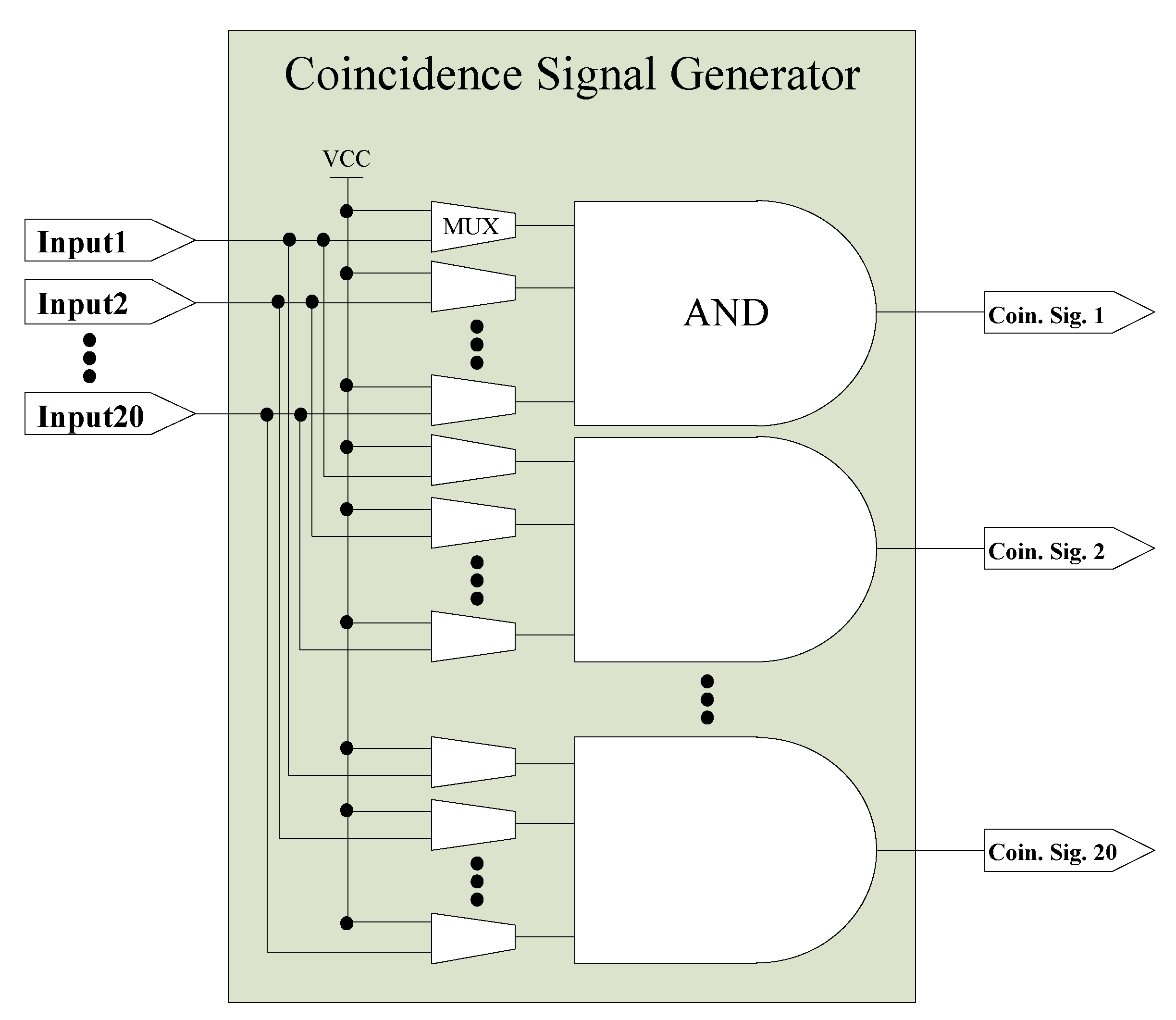
Second, to generate the coincidence signal of arbitrarily selected inputs among the 20 inputs, we developed the coincidence signal generator shown in Figure 3. Using a 20 input AND gate and 20 MUXs, users can arbitrarily select inputs to generate its coincidence signal. For identical performance as an arbitrary configuration, we designed and synthesized the critical path lines carefully. When the user chooses to disable the input, the VCC (high level) is fed in as an input signal of the AND gate instead of the original input signal by using a select input of the MUX. Furthermore, 20 sets of the coincidence signal generator block, consisting of an AND gate and 20 MUXs, generate 20 coincidence signals simultaneously. Each input channel is connected with 20 MUXs of each coincidence signal generator block separately for duplicating the input signals. The duplicated input pulses are distributed among 20 AND gates for generating 20 independent coincidence outputs. Therefore, users can arbitrarily select the combination of inputs for 20 coincidence outputs independently.
Moreover, the GUI program and hardware of the CCU were developed to easily control the configuration of the 20 coincidence outputs. Compared with the previous version, massive system parameters have to be handled due to the 20 inputs and outputs. The parameters of the GUI program are transferred to the functional blocks in an FPGA through a USB connection, as shown in Figure 4. The parameters of the input delay and coincidence time window, which are transferred to the internal delay and pulse-reshaping block, respectively, are controllable in real time with numeric up-down controllers. The parameters of the 20 input combination for coincidence signal generation is controllable with 20 check boxes. Certainly, there are 20 groups of 20 check boxes in the GUI for counting 20 coincidences simultaneously. The accumulation time for the signal count is also adjustable using a numeric up-down controller. The accumulated counts—20 single input counts and 20 coincidences—are concurrently displayed in the textbox. Furthermore, all the data can be stacked up in the GUI program for the user’s needs, which further depends on the computing power of the user.
The overall architecture of the CCU was implemented in an FPGA with 17,476 logic elements (LEs), which is 78% of the usage of a Cyclone4 FPGA chip (EP4CE22F17C6N) from Intel FPGAs, according to a Quartus II compilation report. The rest of the LEs could be used for debugging and additional delay for the electronic input signals. The detailed information of the resource utilization for the CCU is stated in Table 1. All components of the CCU were packaged in a module at a size of 240 × 175 × 50 mm3. In Figure 5, 20 input ports and a USB port for data transmission are placed at front and back sides, respectively, of the packaged box. For experiments demanding more than 20 inputs, the function of the CCU could be made affordable by exchanging the upper version of an FPGA. In fact, 20 channels of the CCU consumed only 10% of the LEs with the Stratix family FPGA. Additionally, the CCU could be developed with an Artix, Kintex, or Virtex family FPGA from different vendors because it only used less than 20,000 conventional logic elements and not special elements.

3. Experiments

To evaluate the 20 channel CCU, we conducted experiments for recognizing four specific features. First, we investigated the range of acceptable input frequencies. To observe the performance, we simultaneously put two synchronized TTL pulses at the input ports of the CCU with a 3 ns coincidence time window. Figure 6 shows the average counting rates as a function of the input frequency. Due to the synchronized input pulses, the coincidence count rates were the same as the single input count rates. The measured single count and the coincidence count rates were equal to the input frequency until the input frequency reached close to 400 MHz. However, as the input frequency exceeded 400 MHz, the coincidence counting rates grew abnormal compared with the input frequency. Above 600 MHz, the coincidence count was almost zero because the amplitude of the coincidence signal became smaller than the acquisition level of the FPGA.
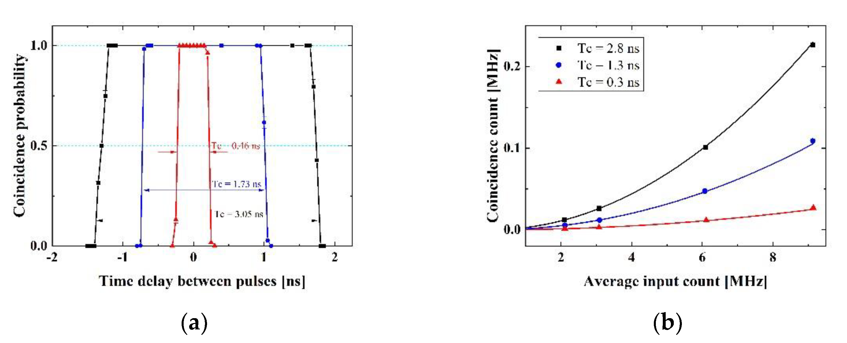
Second, we analyzed the size of the coincidence time window. We generated two synchronized TTL pulse sequences and ensured that one of the pulse sequences could be delayed to accurately measure the coincidence time window. We then put those pulse sequences into each input channel of the CCU. While changing the timing between two pulse sequences, we plotted the ratio of the coincidence (see Figure 7a). We previously noted that the pulse-reshaping block determined the coincidence time window according to the pulse reshaping steps. In Figure 7a, we used pulse reshaping steps of 2, 6, and 10, for which the coincidence time windows were 0.46 ns, 1.73 ns, and 3.05 ns, respectively. Furthermore, we estimated the coincidence time windows more precisely with accidental coincidence counts [35]. When asynchronous random Gaussian pulses are fed into two input channels, we can calculate the coincidence time window TC using the following equation:
TC = RAB/(RA · RB)
where RA, RB, and RAB are single counts of channels A and B and their accidental coincidence counts, respectively. Figure 7b shows the experimental results (dots) and the fitting data (lines). The coincidence windows with pulse reshaping steps of 2, 6, and 10 were set to 0.3 ns, 1.3 ns, and 2.8 ns, respectively. There were some negligible errors of the coincidence time window with the experimental results of Figure 7a,b, which resulted due to different shapes of the input pulses. We used a square wave for the experiment shown in Figure 7a, but Gaussian pulses were applied as inputs for the experiment shown in Figure 7b.
Third, to verify the 20 coincidence outputs, we arbitrary generated four pulses for inputs of the CCU using a function generator. The four input pulses are depicted in Figure 8a. The frequencies of the input pulses were 10 MHz, 5 MHz, 10 MHz, and 10 MHz with pulse widths of 10 ns, 10 ns, 50 ns, and 25 ns, respectively. The input pulses were synchronized with each other. Figure 8b shows that the single counts for the four input pulses were accurately displayed in the GUI program. Obviously, the other single counts were all zero. To detect the coincidences for those inputs, as mentioned before, we could select a 20 input combination for coincidence signal generation using the check boxes. As selected in the configuration setting check boxes, 20 coincidence outputs were counted and shown in the GUI program. Because output text boxes 1–4 of the coincidence count were selected as a single channel, they became around 10 M or 5 M counts, respectively. Two and threefold coincidences were measured in the 5–16 output text boxes, which are not shown at all in the figure. Additionally, fourfold coincidences were measured in output text boxes 17, 18, 19, and 20. All single and coincidence counts were displayed correctly, which means that the 20 outputs of the CCU were operating properly.
Finally, we performed a test to confirm the twentyfold coincidence counting. We used an FPGA and a pulse generator for generating 19 synchronized signals and one timing-controlled signal, respectively. All signals were connected to the inputs of the CCU and reshaped with 3 steps at the pulse-reshaping block. By enabling all the inputs of the AND gate in the coincidence signal generator block, twentyfold coincidence signals were accumulated. We adjusted the signal timing of one input using a pulse generator with a high resolution of 10 ps while holding the 19 synchronized input pulses. We investigated all the channels and noticed that each channel had different coincidence time windows due to different placement of the buffers in the pulse-reshaping blocks. As expected, the buffer delays were minimized with the logic lock function. Despite this consideration, in Figure 9, the coincidence probabilities of the channels have distributions ranging from 1.5 ns to 2.4 ns. The experimental results for each channel are depicted as different colors. It is possible to correct this using additional hardware such as delay chips instead of the buffers in an FPGA. However, a delay chip consumes a lot of current and requires additional efforts to match the features of the inputs, such as electrical noise and the path length of the peripheral circuits.

4. Discussion

We summarized the performance of our CCU with related works in Table 2. The TTL circuit-based CCU has 4 channels and can measure coincidences using all inputs with a relatively coarse coincidence resolution [27]. The FPGA-based CCUs have a relatively large number of input channels, but only a small number of inputs can be measurable for the coincidence [22,32,33]. The TDC-based work is also compared, which has two inputs and can obtain high resolutions of only twofold coincidences [24]. Comparing related works, the proposed CCU offers a maximum twentyfold coincidence measurement with a reasonable coincidence window and a high counting rate. With this CCU, we expect that multi-qubit experiments for quantum computing can be supported, and the correlation of the qubits is more easily detected and revealed. Moreover, the CCU can be built in chip scale for housing a portable device at a relatively lower cost.

5. Conclusions

We proposed a 20 channel CCU using a low-end FPGA. It has 20 inputs and 40 outputs for measuring up to twentyfold coincidences. The experimental results show that the measurement of a twentyfold coincidence was performed well, with less than 0.5 ns for the coincidence window. Since all the required functions are implemented in the FPGA, one can easily manipulate and arbitrarily configure the CCU for specific experiments using the GUI. With the consideration of the architectures for multifold coincidence, our CCU is ready to be employed in quantum experiments that utilize multi-qubit states.

Author Contributions

Conceptualization, B.K.P. and Y.-S.K.; methodology, B.K.P.; software, B.K.P.; validation, Y.-W.C., S.M. and S.-W.H.; formal analysis, B.K.P.; investigation, Y.-S.K. and Y.-W.C.; resources, S.M. and S.-W.H.; data curation, B.K.P.; writing—original draft preparation, B.K.P.; writing—review and editing, S.-W.H.; visualization, S.-W.H.; supervision, S.-W.H.; project administration, S.-W.H.; funding acquisition, S.-W.H. All authors have read and agreed to the published version of the manuscript.

Funding

This research was funded by the Korea Institute of Science and Technology, grant number 2E30620; the National Research Foundation of Korea, grant numbers 2019M3E4A107866011, 2019M3E4A1079777, and 2019R1A2C2006381; and the Institute for Information and Communications Technology Promotion, grant numbers 2020-0-00947 and 2020-0-00972.

Conflicts of Interest

The authors declare no conflict of interest.

References

  1. Kwon, O.; Cho, Y.-W.; Kim, Y.-H. Single-mode coupling efficiencies of type-II spontaneous parametric down-conversion: Collinear, noncollinear, and beamlike phase matching. Phys. Rev. A 2008, 78, 053825. [Google Scholar] [CrossRef] [Green Version]
  2. Kwon, O.; Ra, Y.-S.; Kim, Y.-H. Observing photonic de Broglie waves without the maximally-path-entangled| N, 0〉+| 0, N〉 state. Phys. Rev. A 2010, 81, 063801. [Google Scholar] [CrossRef] [Green Version]
  3. Kim, Y.-S.; Kwon, O.; Lee, S.M.; Lee, J.-C.; Kim, H.; Choi, S.-K.; Park, H.S.; Kim, Y.-H. Observation of Young’s double-slit interference with the three-photon N00N state. Opt. Express 2011, 19, 24957–24966. [Google Scholar] [CrossRef] [Green Version]
  4. Pan, J.-W.; Chen, Z.-B.; Lu, C.-Y.; Weinfurter, H.; Zeilinger, A.; Żukowski, M. Multiphoton entanglement and interferometry. Rev. Mod. Phys. 2012, 84, 777–838. [Google Scholar] [CrossRef]
  5. Kim, Y.-S.; Slattery, O.; Kuo, P.S.; Tang, X. Conditions for two-photon interference with coherent pulses. Phys. Rev. A 2013, 87, 063843. [Google Scholar] [CrossRef] [Green Version]
  6. Ra, Y.-S.; Tichy, M.C.; Lim, H.-T.; Kwon, O.; Mintert, F.; Buchleitner, A.; Kim, Y.-H. Observation of detection-dependent multi-photon coherence times. Nat. Commun. 2013, 4, 2451. [Google Scholar] [CrossRef] [PubMed] [Green Version]
  7. Kim, Y.; Kim, Y.-S.; Lee, S.-Y.; Han, S.-W.; Moon, S.; Kim, Y.-H.; Cho, Y.-W. Direct quantum process tomography via measuring sequential weak values of incompatible observables. Nat. Commun. 2018, 9, 192. [Google Scholar] [CrossRef]
  8. Pramanik, T.; Cho, Y.-W.; Han, S.-W.; Lee, S.-Y.; Kim, Y.-S.; Moon, S. Revealing hidden quantum steerability using local filtering operations. Phys. Rev. A 2019, 99, 030101. [Google Scholar] [CrossRef] [Green Version]
  9. Cho, Y.-W.; Kim, Y.; Choi, Y.-H.; Kim, Y.-S.; Han, S.-W.; Lee, S.-Y.; Moon, S.; Kim, Y.-H. Emergence of the geometric phase from quantum measurement back-action. Nat. Phys. 2019, 15, 665–670. [Google Scholar] [CrossRef]
  10. Pramanik, T.; Cho, Y.-W.; Han, S.-W.; Lee, S.-Y.; Moon, S.; Kim, Y.-S. Nonlocal quantum correlations under amplitude damping decoherence. Phys. Rev. A 2019, 100, 042311. [Google Scholar] [CrossRef] [Green Version]
  11. Lo, H.-K.; Curty, M.; Qi, B. Measurement-Device-Independent Quantum Key Distribution. Phys. Rev. Lett. 2012, 108, 130503. [Google Scholar] [CrossRef] [PubMed] [Green Version]
  12. Liu, Y.; Chen, T.-Y.; Wang, L.-J.; Liang, H.; Shentu, G.-L.; Wang, J.; Cui, K.; Yin, H.-L.; Liu, N.-L.; Li, L.; et al. Experimental Measurement-Device-Independent Quantum Key Distribution. Phys. Rev. Lett. 2013, 111, 130502. [Google Scholar] [CrossRef] [Green Version]
  13. Tang, Z.; Liao, Z.; Xu, F.; Qi, B.; Qian, L.; Lo, H.-K. Experimental Demonstration of Polarization Encoding Measurement-Device-Independent Quantum Key Distribution. Phys. Rev. Lett. 2014, 112, 190503. [Google Scholar] [CrossRef] [PubMed] [Green Version]
  14. Choi, Y.; Kwon, O.; Woo, M.; Oh, K.; Han, S.-W.; Kim, Y.-S.; Moon, S. Plug-and-play measurement-device-independent quantum key distribution. Phys. Rev. A 2016, 93, 032319. [Google Scholar] [CrossRef] [Green Version]
  15. Park, C.H.; Woo, M.K.; Park, B.K.; Lee, M.S.; Kim, Y.-S.; Cho, Y.-W.; Kim, S.; Han, S.-W.; Moon, S. Practical Plug-and-Play Measurement-Device-Independent Quantum Key Distribution with Polarization Division Multiplexing. IEEE Access 2018, 6, 58587–58593. [Google Scholar] [CrossRef]
  16. Acremann, Y.; Chembrolu, V.; Strachan, J.P.; Tyliszczak, T.; Stöhr, J. Software defined photon counting system for time resolved x-ray experiments. Rev. Sci. Instruments 2007, 78, 14702. [Google Scholar] [CrossRef] [PubMed]
  17. Zhong, H.-S.; Li, Y.; Li, W.; Peng, L.-C.; Su, Z.-E.; Hu, Y.; He, Y.-M.; Ding, X.; Zhang, W.; Li, H.; et al. 12-Photon Entanglement and Scalable Scattershot Boson Sampling with Optimal Entangled-Photon Pairs from Parametric Down-Conversion. Phys. Rev. Lett. 2018, 121, 250505. [Google Scholar] [CrossRef] [PubMed] [Green Version]
  18. Zhong, H.-S.; Wang, H.; Deng, Y.-H.; Chen, M.-C.; Peng, L.-C.; Luo, Y.-H.; Qin, J.; Wu, D.; Ding, X.; Hu, Y.; et al. Quantum computational advantage using photons. Science 2020, 370, 1460. [Google Scholar]
  19. Crotti, M.; Rech, I.; Ghioni, M. Four Channel, 40 ps Resolution, Fully Integrated Time-to-Amplitude Converter for Time-Resolved Photon Counting. IEEE J. Solid-State Circuits 2011, 47, 699–708. [Google Scholar] [CrossRef]
  20. Wu, J.; Zhang, W.; Yu, X.; Jiang, Q.; Zheng, L.; Sun, W. A hybrid time-to-digital converter based on residual time extraction and amplification. Microelectron. J. 2017, 63, 148–154. [Google Scholar] [CrossRef]
  21. Arabul, E.; Rarity, J.; Dahnoun, N. FPGA based fast integrated real-time multi coincidence counter using a time-to-digital converter. In Proceedings of the IEEE 2018 7th Mediterranean Conference on Embedded Computing (MECO), Budva, Montenegro, 10–14 June 2018; pp. 1–4. [Google Scholar]
  22. Li, W.; Hu, Y.; Zhong, H.-S.; Wang, Y.-F.; Wang, X.-L.; Peng, C.-Z.; Jiang, X. Time-tagged coincidence counting unit for large-scale photonic quantum computing. Rev. Sci. Instruments 2018, 89, 103113. [Google Scholar] [CrossRef]
  23. Machado, R.; Cabral, J.; Alves, F.S. All-Digital Time-to-Digital Converter Design Methodology Based on Structured Data Paths. IEEE Access 2019, 7, 108447–108457. [Google Scholar] [CrossRef]
  24. Chen, P.; Lan, J.-T.; Wang, R.-T.; Qui, N.M.; Marquez, J.C.J.S.; Kajihara, S.; Miyake, Y. High-Precision PLL Delay Matrix With Overclocking and Double Data Rate for Accurate FPGA Time-to-Digital Converters. IEEE Trans. Very Large Scale Integr. (VLSI) Syst. 2020, 28, 904–913. [Google Scholar] [CrossRef]
  25. Gaertner, S.; Weinfurter, H.; Kurtsiefer, C. Fast and Compact Multichannel Photon Coincidence Unit for Quantum Information Processing. Rev. Sci. Instruments 2005, 76, 123108. [Google Scholar] [CrossRef] [Green Version]
  26. Branning, D.; Bhandari, S.; Beck, M. Low-cost Coincidence-Counting Electronics for Undergraduate Quantum Optics. Am. J. Phys. 2009, 77, 667–670. [Google Scholar] [CrossRef] [Green Version]
  27. Branning, D.; Khanal, S.; Shin, Y.H.; Clary, B.; Beck, M. Note: Scalable Multiphoton Coincidence-Counting Electronics. Rev. Sci. Instruments 2011, 82, 016102. [Google Scholar] [CrossRef] [Green Version]
  28. Ko, G.B.; Yoon, H.S.; Kwon, S.I.; Hong, S.J.; Lee, N.S.; Lee, J.S. Development of FPGA-based Coincidence Units with Veto Function. Biomed. Eng. Lett. 2011, 1, 27–31. [Google Scholar] [CrossRef]
  29. Zhu, F.-M.; Hsieh, S.; Yen, W.; Chou, H. A digital coincidence measurement system using FPGA techniques. Nucl. Instruments Methods Phys. Res. Sect. A Accel. Spectrometers Detect. Assoc. Equip. 2011, 652, 454–457. [Google Scholar] [CrossRef]
  30. DE2-115 CCU. Available online: http://people.whitman.edu/~beckmk/QM/circuit/circuit.html (accessed on 19 January 2021).
  31. Park, B.K.; Kim, Y.-S.; Kwon, O.; Han, S.-W.; Moon, S. High-performance reconfigurable coincidence counting unit based on a field programmable gate array. Appl. Opt. 2015, 54, 4727–4731. [Google Scholar] [CrossRef]
  32. Zhang, C.; Li, W.; Hu, Y.; Yang, T.; Jin, G.; Jiang, X. 48-channel coincidence counting system for multiphoton experiment. Rev. Sci. Instruments 2016, 87, 113107. [Google Scholar] [CrossRef]
  33. Gupta, A.K.; Prasad, R.S.; Srivani, L.; Murthy, D.T.; Panigrahi, B.K.; Raghavan, G. Design and Development of Flexible and Low-Cost Coincidence Counting Unit. In Proceedings of the 2018 IEEE International Conference on Electronics, Computing and Communication Technologies (CONECCT), Bangalore, India, 16–17 March 2018; pp. 1–4. [Google Scholar]
  34. Arabul, E.; Paesani, S.; Tancock, S.; Rarity, J.G.; Dahnoun, N. A Precise High Count-Rate FPGA Based Multi-Channel Coincidence Counting System for Quantum Photonics Applications. IEEE Photon- J. 2020, 12, 1–14. [Google Scholar] [CrossRef]
  35. Eckart, C.; Shonka, F.R. Accidental Coincidences in Counter Circuits. Phys. Rev. 1938, 53, 752–756. [Google Scholar] [CrossRef]
Figure 1. Overall architecture of the coincidence counting unit (CCU). All the required functional blocks are implemented in a low-end field-programmable gate array (FPGA). The processor controls all the functional blocks and transfers data to a personal computer via a USB connection. All the parameters can be controlled with the graphical user interface (GUI) software.
Electronics 10 00569 g001
Figure 2. (a) Schematic of the pulse-reshaping block and timing diagram for (b) shortening the pulse width, (c) widening the pulse width, and (d) a malfunction case.
Electronics 10 00569 g002
Figure 3. Schematic of the coincidence signal generator. It consists of 20 input AND gates and multiplexers (MUXs). Each AND gate generates a coincidence signal, and the MUXs determine the combination of inputs for the coincidence output.
Electronics 10 00569 g003
Figure 4. GUI program of the CCU.
Electronics 10 00569 g004
Figure 5. Packaging module of the CCU.
Electronics 10 00569 g005
Figure 6. Coincidence counting rate versus synchronized input frequency.
Electronics 10 00569 g006
Figure 7. (a) Coincidence probability versus the time interval between two input pulses with three coincidence time windows (TC). (b) Accidental coincidence counting rates of the different coincidence time windows versus the average input count rates.
Electronics 10 00569 g007
Figure 8. (a) Four arbitrary generated inputs and (b) its 4 single and 20 coincidence counts displayed on the GUI program.
Electronics 10 00569 g008
Figure 9. Twentyfold coincidence probability versus the time delay between one input and the other inputs.
Electronics 10 00569 g009
Table 1. Utilization of FPGA resources (EP4CE22F17C6N).
ResourceUtilization/Available
Total logic elements17,476/22,320 (78%)
Registers4101/22,320 (18%)
Pins27/154 (18%)
Memory279,552/608,256 (46%)
PLL1/4 (25%)
Table 2. Performance comparison of CCUs.
CCU1 [27]CCU2 [22]CCU3 [32]CCU4 [33]TDC [24]This Work
Number of channels432488220
Measurable
coincidence folds
4868220
Minimum coincidence time window12 ns0.39 ns0.3 ns10 ns15.6 ps0.46 ns
Maximum
counting rate
84 MHz80 MHz96 MHz50 MHz50 MHz400 MHz
Publisher’s Note: MDPI stays neutral with regard to jurisdictional claims in published maps and institutional affiliations.