Abstract
To address atmospheric attenuation and path loss issues in the mmwave portion of the spectrum, high gain and narrow beam antenna systems are essential for the next generation communication networks. This paper presents a novel hook-shaped antenna array for 28 GHz 5G mmwave applications. The proposed antenna was fabricated on commercially available Rogers 5880 substrate with thickness of 0.508 mm and dimensions of 10 × 8 mm. The proposed shape consists of a circle with an arc-shaped slot on top of it and T-shaped resonating lengths are introduced in order to attain broad band characteristics having gain of 3.59 dBi with radiation and total efficiency of 92% and 86% for single element. The proposed structure is transformed into a four-element array with total size of 26.9 × 18.5 mm in order to increase the gain up to 10.3 dBi at desired frequency of interest. The four-element array is designed such that it exhibits dual-beam response over the entire band of interest and the simulated results agree with fabricated prototype measurements. The proposed antenna array, because of its robustness, high gain, and dual-beam characteristics can be considered as a potential candidate for the next generation 5G communication systems.
1. Introduction
With the evolution of the universal telecommunication system, 5G technology has now become the center of interest due to its higher data rates capacity and low latency over the entire communication link. The currently available sub 6 GHz spectrum is already choking up with the immense pressure of applications, and physical communication needs to be established for millimeter wave (mmwave) with unlicensed and unlimited bandwidth to be utilized [1,2]. With available feasibility reports, it is noteworthy that mmwave-range communication is a promising candidate for providing wider bandwidth, low latency, and higher data throughputs. In the mmwave band, several bands have been allotted as potential candidates for future 5G standards such as the 28 and 38 GHz spectra, while 57–64 (O band) and 164–200 GHz (H O band) have been declared as unlicensed frequency bands [3,4]. The higher portion of the spectrum is helpful to achieve higher data rates and bandwidth goals. However, these frequencies are quite sensitive to atmospheric attenuation, which can deteriorate the user experience of 5G services [5]. One of the easies and most appropriate solutions available to encounter these issues is to deploy antenna with a high gain and possessing a directive radiation beam in order to ensure quality of service of received signals at the user side [6,7]. Several studies have been conducted on mmwave spectrum in recent years. However, few studies have been performed on the 28 GHz band to tackle the gain challenges with single-feed antennas holding quite narrow and directive radiation beams. In [8], a multiple input–multiple output (MIMO) antenna is presented for mmwave applications covering the 28 GHz frequency band. The four port MIMO system provides a maximum gain of 5.5 dBi with pattern diversity characteristics due to its geometrical placement of resonating elements. However, the achieved gain is not suitable to tackle the atmospheric attenuation challenges at the desired band. Similarly, a four-port infinity shell-shaped antenna array was presented by Kamal et al. [9] at 28 GHz having maximum gain of 7 dBi and ECC less than 0.15 over the entire band of interest. However, the gain of the proposed system is comparatively less for MIMO systems. SIW are known to have low transmission losses. For example, in [10], a Substrate Integrated Waveguide (SIW) antenna having large dimensions of 70 × 63.5 mm with multilayered geometry is presented possessing high gain of nearly 14 dBi with low side lobe levels. However, the vias assembly in the antenna makes the structure more complex and difficult to handle. In [11], with a relatively small size of 28.8 × 28.8 mm, a SIW antenna array is presented offering high gain of 26 dBi and bandwidth ranging 57–71 GHz, but the multilayered substrate assembly with bonding films makes it complex in nature to assemble. A four-element broadband wire hexagonal SIW array having dimensions of 45 × 20 × 0.254 mm is presented in [12] operating at frequency of 28 GHz with high gain of 10.12 dBi and radiation efficiency greater than 85% over the entire bandwidth. Although the SIW array presented satisfactory results with narrow beamwidth, the vias assembly are too compact with distance of less than 1 mm and the geometry of the structure with such dense number and close proximity of vias makes the reported SIW antenna more complex and bulky to handle. On the other hand, planar antennas are easy to assemble and design but with the constraints of moderate transmission losses, which can be neglected with careful modeling [13,14,15,16,17]. In [18], a planar dipole, resembling a shape, four-element linear array is presented at 28 GHz radiating alongside its endfire direction with narrow bandwidth of 14.6 degrees. The array offers 10.7 dBi gain and high impedance bandwidth of 35.5% with dimensions of 37.4 mm × 14.6 mm. Similarly, in [19], a simple 3 × 3 planar microstrip phased array antenna operating at 28 GHz is presented. It has a high gain of 15.6 dBi and 1.7 GHz bandwidth with a small 20 × 20 mm size. Similarly, Khan et al. [20] presented a microstrip patch antenna with dual-band operation at 28 and 38 GHz. Although a satisfactory gain of 12 dB was achieved at both operating frequency bands, it had a very low bandwidth, i.e, <1 GHz. Furthermore, the proposed antenna does not hold dual-beam radiation characteristic. Likewise, a very wideband antenna covering the frequency band of 23–40 GHz is presented in [21] for 5G communication applications. Although the antenna possesses wide bandwidth, the antenna radiation pattern seems to be quite dispersed as many side and back lobes are observed in the radiation pattern of the proposed antenna, which are undesirable in the case of higher-band operation.
As the attenuation and path losses in mmwave spectrum due to environmental effects are unrelentingly intense, the antenna systems must radiate with high gain to withstand such effects. This high gain is achievable with narrow and directional beam widths. Furthermore, in mmwave spectrum, the high bandwidth is mandatory for high data rates, which, for planar antenna arrays, becomes a difficult task to achieve simultaneously since planar structures are known to have very small bandwidth response. In general, a planar structure based on its reliable performance will always be preferred since it is easy to implement and cost effective.
This paper presents a novel modified four-element hook-shaped planar array formed in linear manner. The proposed planar array exhibits dual-beam response with very narrow beamwidth of 13.5 degrees and a peak gain of 10.3 dBi, ensuring that it is a promising candidate for future 5G mmwave systems.
2. Antenna Design
Figure 1 shows the proposed antenna design. The proposed antenna is modeled on a Rogers RT Duroid 5880 substrate with a thickness of 0.508 mm, dielectric constant of 2.2, and loss tangent of 0.0009. Table 1 shows the optimized parametric values of the proposed planar structure.
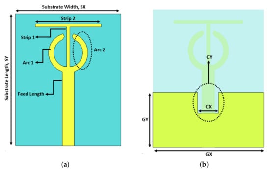
Figure 1.
Proposed antenna design: (a) front view; and (b) back view.

Table 1.
Design parameters.
The width of the feed line is kept at 0.9 mm. The ground plane is kept less than partial in size and is introduced with small square cut. This cut helps in parameter tuning of the structure to the desired frequency response. The proposed antenna evolved in four steps to resonate at the desired frequency, which is 28 GHz. In first step, the feed line was introduced with an arc resembling in structure a hook. In the second stage, the proposed design preceded with a copy of the first arc adjacent to each other. In the third stage, in between the arc’s opening, a thin strip was added having width of 0.2 mm and length of 1.5 mm that generated some resonance but not at the desired value. In the proposed design, an extra strip was introduced on top of the first strip to increase the electrical length of the design. This assembly generated the desired frequency response with the return loss value of −22 dB. Figure 2a shows the proposed antenna’s four-stage design evolution with reflection co-efficient response. It can be seen that the desired results are achieved with the combination of the arc and T-shaped strips. However, Figure 2b shows how the response would be if only the T-shaped strip contributed to make the proposed antenna resonant at the desired band. It is observed that varying the strip 2 parameter, first to 4 mm, makes the proposed antenna resonant at nearly 43 GHz. Increasing that parameter up to 9.5 mm gives a resonance at the desired band of 28 GHz as compared to our proposed model with arcs (Figure 2a), where the same response is achieved at 3 mm length of strip 2 parameter. By removing these arc shape strips, if the proposed antenna with a T-shaped strip having a 9.5 mm strip 2 length were transformed into a four-element array, the size of the antenna array would become quite large, most likely twice the size of the array structure that could be achieve using the concept in Figure 2a, which is undesirable at the mmwave band. This is due to the consideration of a sufficient distance between antenna elements to avoid a coupling effect among them. Thus, the antenna element presented in Figure 2a is chosen for the array structure.
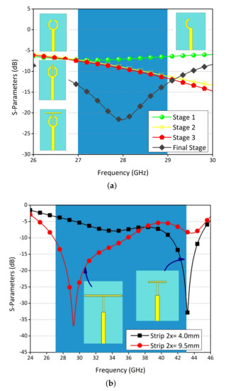
Figure 2.
Design Evolution (a) Four-stage design evolution (b) Design Evoultion w.r.t T strips.
In the proposed design (Figure 2a), the parameters strip 1 and strip 2 are the tuning parameters of the antenna. Figure 3, Figure 4 and Figure 5 show the parametric modeling of the proposed antenna to the desired resonance frequency of 28 GHz. It was observed that the strip 1 length has more effect with variation in its parametric sweep. The resonance jumped due to its sensitivity around the strip 1 length, thus we can conclude that strip 1 can further be analyzed to tune the parametric response to other resonances. Feed length, or what can be termed as Feed Y parametric sweep, showed high sensitivity as well in terms of the reflection co-efficient response of the proposed antenna. At the optimal value of 7.3 mm, the desired resonance is achieved at low return loss value of −36 dB. Figure 3d shows the final obtained reflection co-efficient value of proposed design.
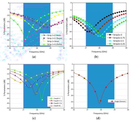
Figure 3.
Reflection co-efficient: (a) strip 1 sweep; (b) strip 2 sweep; (c) feed length sweep; and (d) final single element.
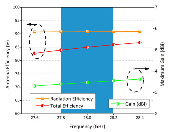
Figure 4.
Performance parameters of the proposed antenna.
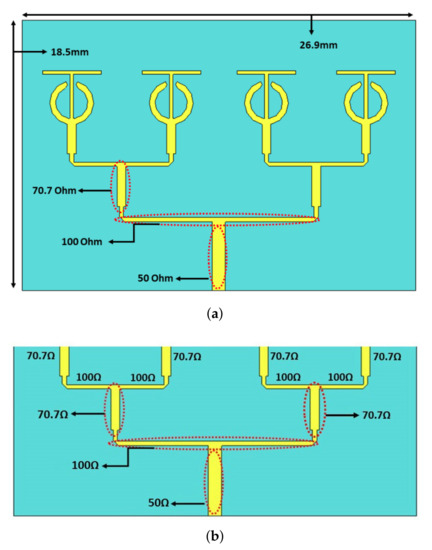
Figure 5.
Proposed antenna array transformation: (a) array structure; and (b) equivalent model for impedance distribution.
The performance parameters obtained for the proposed antenna are presented in Figure 4. The figure shows that the proposed design has radiation efficiency up to 91% and total efficiency of 86% at the desired resonance frequency due to the fact that the proposed radiating element is designed as a thin substrate. The gain over the entire band of interest ranges 3.1–3.79 dBi, which is quite good for single element.
3. Array Transformation
The proposed antenna design is transformed into a four-element array network to enhance the gain at the desired frequency of interest from 3.59 to 10.3 dBi. The array network is transformed by splitting the main 50 ohm feed into 100 ohm track impedance. If we split the 100 ohm tracks again, we would require a 200 ohm line, which is often practically impossible to produce. Instead, we use a quarter wave transformer to match back down to 50 ohm, and then once again split the track into two 100 ohm lines. Figure 5a shows the proposed antenna array configuration, while an equivalent model for the array structure impedance distribution is shown in Figure 5b. The main feed line width is adjusted to get an impedance of 50 , while for other transmission lines’ feed line width is adjusted to get an impedance of 100 and 70.7 , respectively. The feed line width for the desired impedance achievement is estimated with the help of the following expression [20]:
Here, is the impedance of the feed line, is the thickness of substrate, and is the width of a feed line for a dedicated impedance.
4. Fabrication and Measurements
The proposed antenna array was fabricated and measurements were performed in the in-house facility. Figure 6 shows the proposed four-element antenna array. The reflection co-efficient was measured using a vector network analyzer. It should be noted that the element spacing among each radiating element was kept at 8 mm, which indicates 0.72 lambda distance in order to reduce the mutual coupling effects.
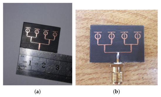
Figure 6.
Fabricated prototype of proposed antenna design: (a) with scale; and (b) without scale.
Figure 7 shows the reflection co-efficient of both the simulated array and the measured array. Although the bandwidth was reduced from 26.9 to 29.3 GHz and the measured results are slightly shifted, which can be attributed to the connector, cable losses, or human errors, the overall performance of the system is satisfactory.
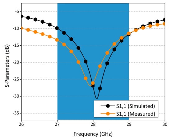
Figure 7.
Reflection co-efficient of the proposed array.
The simulated and measured total efficiency with gain over the desired band of interest is given in Figure 8. Both simulated and measured efficiency of the proposed antenna is above 83% in the entire operational band of the antenna. Upon the formation of the proposed single-element antenna into a four-element array, the increase in gain achieved was 7 dBi. Thus, at the main resonance frequency, the gain value achieved is 10.3 dBi, which is very desirable for mmwave systems.
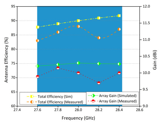
Figure 8.
Gain and efficiency plots of the antenna array.
Figure 9 presents the proposed antenna array normalized radiation patterns, both simulated and measured, in both principle planes of Phi = 0 and Phi = 90. The radiation patterns were normalized to 5 dB. In phi = 90 plane, the proposed antenna array is radiating in all directions with the exception of two nulls located at the top and bottom. In Phi = 0 plane, the antenna is highly directive with two beams located at the top and bottom of the antenna with the simulated beam-width of 21 degrees, which is well suited for future mobile networks. The simulated and measured results match each other with slight variations. The proposed antenna array with additional gain of 6.5 dBi, as compared to single-element and dual-beam response located at 180 degree with respect to each other, can be termed as a potential candidate for future mmwave applications.
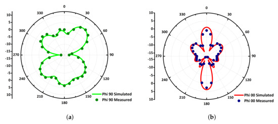
Figure 9.
Radiation patterns: (a) Phi = 90; and (b) Phi = 00.
Table 2 shows the proposed antenna comparison with published work. The size of the proposed antenna is still good compared to the reported ones and privileged the very good bandwidth and gain. Thus, in short, the main novelty of the proposed work is the achievement of wide-bandwidth (3 GHz), more than 10 dB gain, and dual-beam feature with a low level of unwanted lobes in the radiation pattern, simultaneously in a compact design as compared to the existing state of the art, which makes our proposed design a competent candidate for future 5G communication based on mmwave.
Table 2.
Comparison table.
5. Conclusions
This paper presents a novel hook-shaped antenna in 28 GHz band for mmwave applications with broadband characteristics. The proposed antenna offers 3.65 dBi gain for single element with other better performance characteristics. Moreover, the transformation of the proposed antenna into a four-element array for mmwave system boosted gain up to 10.3 dBi with radiation and total efficiency greater than 85%. The array radiates with two distinct beams located at 0 and 180 degrees with narrow bandwidths, and thus has potential for several spatial diversity applications. The proposed antenna offers small size of 10 × 8 mm for single element and 26.9 × 19.5 mm for array. A prototype of the proposed dual-beam antenna array was developed and the measured results agree with the simulated results. Because of efficient performance, features and unique design, the proposed antenna can be termed as a potential candidate for future high-speed mmwave communication systems.
Author Contributions
Conceptualization, M.M.K. and S.H.K.; methodology, M.M.K. and S.Y.; software, M.M.K., S.H.K., and M.A. (Mujeeb Abdullah); validation, S.Y. and M.A. (Mohammad Alibakhshikenari); formal analysis, M.A. (Mujeeb Abdullah) and M.A. (Mohammad Alibakhshikenari); investigation, M.A. (Mujeeb Abdullah), M.A. (Mohammad Alibakhshikenari), and M.M.; resources, M.A. (Mohammad Alibakhshikenari), F.F., E.L., and M.M.; data curation, M.M.K.; writing—original draft preparation, D.A.S. and S.H.K.; writing—review and editing, D.A.S., S.H.K., and M.A. (Mohammad Alibakhshikenari); visualization, M.M.K. and M.A. (Mohammad Alibakhshikenari); supervision, S.Y.; project administration, F.F. and E.L.; and funding acquisition, M.A. (Mohammad Alibakhshikenari). All authors have read and agreed to the published version of the manuscript.
Funding
This work was partially supported by RTI2018-095499-B-C31, Funded by Ministerio de Ciencia, Innovación y Universidades, Gobierno de España (MCIU/AEI/FEDER, UE).
Data Availability Statement
All data produced in the study are mentioned in the article.
Conflicts of Interest
The authors declare no conflict of interest.
References
- Zhang, J.; Yu, X.; Letaief, K.B. Hybrid beamforming for 5 G and beyond millimeter-wave systems: A holistic view. IEEE Open J. Commun. Soc. 2019, 1, 77–91. [Google Scholar] [CrossRef]
- Kiani, S.H.; Altaf, A.; Abdullah, M.; Muhammad, F.; Shoaib, N.; Anjum, M.R.; Damaševičius, R.; Blažauskas, T. Eight Element Side Edged Framed MIMO Antenna Array for Future 5 G Smart Phones. Micromachines 2020, 11, 956. [Google Scholar] [CrossRef] [PubMed]
- Przesmycki, R.; Bugaj, M.; Nowosielski, L. Broadband Microstrip Antenna for 5 G Wireless Systems Operating at 28 GHz. Electronics 2021, 10, 1. [Google Scholar] [CrossRef]
- Hilt, A. Availability and Fade Margin Calculations for 5 G Microwave and Millimeter-Wave Anyhaul Links. Appl. Sci. 2019, 9, 5240. [Google Scholar] [CrossRef]
- Khan, J.; Sehrai, D.A.; Khan, M.A.; Khan, H.A.; Ahmad, S.; Ali, A.; Arif, A.; Memon, A.A.; Khan, S. Design and performance comparison of rotated Y-shaped antenna using different metamaterial surfaces for 5 G mobile devices. CMC Comput. Mater. Contin 2019, 60, 409–420. [Google Scholar] [CrossRef]
- Zhekov, S.S.; Zhao, K.; Franek, O.; Zhang, S. Test Reduction for Power Density Emitted by Handset mmWave Antenna Arrays. IEEE Access 2021, 9, 23127–23138. [Google Scholar] [CrossRef]
- Yang, Q.; Gao, S.; Luo, Q.; Wen, L.; Ban, Y.L.; Ren, X.; Wu, J.; Yang, X.; Liu, Y. Millimeter-wave dual-polarized differentially fed 2-D multibeam patch antenna array. IEEE Trans. Antennas Propag. 2020, 68, 7007–7016. [Google Scholar] [CrossRef]
- Rahman, S.; Ren, X.C.; Altaf, A.; Irfan, M.; Abdullah, M.; Muhammad, F.; Anjum, M.R.; Mursal, S.N.F.; AlKahtani, F.S. Nature inspired MIMO antenna system for future mmWave technologies. Micromachines 2020, 11, 1083. [Google Scholar] [CrossRef]
- Kamal, M.M.; Yang, S.; Ren, X.C.; Altaf, A.; Kiani, S.H.; Anjum, M.R.; Iqbal, A.; Asif, M.; Saeed, S.I. Infinity Shell Shaped MIMO Antenna Array for mm-Wave 5 G Applications. Electronics 2021, 10, 165. [Google Scholar] [CrossRef]
- Park, S.J.; Shin, D.H.; Park, S.O. Low side-lobe substrate-integrated-waveguide antenna array using broadband unequal feeding network for millimeter-wave handset device. IEEE Trans. Antennas Propag. 2015, 64, 923–932. [Google Scholar] [CrossRef]
- Zhu, Q.; Ng, K.B.; Chan, C.H.; Luk, K.M. Substrate-integrated-waveguide-fed array antenna covering 57–71 GHz band for 5 G applications. IEEE Trans. Antennas Propag. 2017, 65, 6298–6306. [Google Scholar] [CrossRef]
- Ullah, H.; Tahir, F.A. A broadband wire hexagon antenna array for future 5 G communications in 28 GHz band. Microw. Opt. Technol. Lett. 2019, 61, 696–701. [Google Scholar] [CrossRef]
- Ullah, H.; Tahir, F.A. A Novel Snowflake Fractal Antenna for Dual-Beam Applications in 28 GHz Band. IEEE Access 2020, 8, 19873–19879. [Google Scholar] [CrossRef]
- Zhang, J.; Ge, X.; Li, Q.; Guizani, M.; Zhang, Y. 5 G millimeter-wave antenna array: Design and challenges. IEEE Wirel. Commun. 2016, 24, 106–112. [Google Scholar] [CrossRef]
- Yang, B.; Yu, Z.; Dong, Y.; Zhou, J.; Hong, W. Compact tapered slot antenna array for 5 G millimeter-wave massive MIMO systems. IEEE Trans. Antennas Propag. 2017, 65, 6721–6727. [Google Scholar] [CrossRef]
- Shoaib, N.; Shoaib, S.; Khattak, R.Y.; Shoaib, I.; Chen, X.; Perwaiz, A. MIMO antennas for smart 5 G devices. IEEE Access 2018, 6, 77014–77021. [Google Scholar] [CrossRef]
- Jilani, S.F.; Alomainy, A. Millimetre-wave T-shaped antenna with defected ground structures for 5 G wireless networks. In Proceedings of the 2016 Loughborough Antennas & Propagation Conference (LAPC), Loughborough, UK, 14–15 November 2016; pp. 1–3. [Google Scholar]
- Ullah, H.; Tahir, F.A. A high gain and wideband narrow-beam antenna for 5 G millimeter-wave applications. IEEE Access 2020, 8, 29430–29434. [Google Scholar] [CrossRef]
- Khalily, M.; Tafazolli, R.; Rahman, T.; Kamarudin, M. Design of phased arrays of series-fed patch antennas with reduced number of the controllers for 28-GHz mm-wave applications. IEEE Antennas Wirel. Propag. Lett. 2015, 15, 1305–1308. [Google Scholar] [CrossRef]
- Khan, J.; Sehrai, D.A.; Ali, U. Design of dual band 5 G antenna array with SAR analysis for future mobile handsets. J. Electr. Eng. Technol. 2019, 14, 809–816. [Google Scholar] [CrossRef]
- Sehrai, D.A.; Abdullah, M.; Altaf, A.; Kiani, S.H.; Muhammad, F.; Tufail, M.; Irfan, M.; Glowacz, A.; Rahman, S. A novel high gain wideband MIMO antenna for 5 G millimeter wave applications. Electronics 2020, 9, 1031. [Google Scholar] [CrossRef]


Publisher’s Note: MDPI stays neutral with regard to jurisdictional claims in published maps and institutional affiliations. |
© 2021 by the authors. Licensee MDPI, Basel, Switzerland. This article is an open access article distributed under the terms and conditions of the Creative Commons Attribution (CC BY) license (http://creativecommons.org/licenses/by/4.0/).