Article

Robust Partial Feedback Linearized Controller Design for Standalone Hybrid PV-BES System

School of Engineering and Information Technology, The University of New South Wales, Canberra, ACT 2612, Australia
*
Authors to whom correspondence should be addressed.
Electronics 2021, 10(7), 772; https://doi.org/10.3390/electronics10070772
Submission received: 11 March 2021 / Revised: 20 March 2021 / Accepted: 22 March 2021 / Published: 25 March 2021
(This article belongs to the Section Power Electronics)

Abstract

:
This paper presents a mixed-sensitivity-based robust H loop-shaping partial feedback linearized control scheme to enhance the transient stability of a battery energy storage-associated standalone solar photovoltaic system. The proposed control scheme has been provided independent operating points for a generalized nonlinear dynamical model of DC microgrids connected standalone hybrid solar photovoltaic and battery energy storage system. A parametric uncertainty model is developed for the generalized dynamical model, and the noise disengaging merit of the proposed control technique has been investigated. The designed controller’s performance has been demonstrated under four different scenarios, and it is compared with the conventional PI controller for partial feedback linearized control law.

1. Introduction

Currently, renewable energy sources (RESs) are substituting traditional fossil fuel to produce electrical energy due to their ecologically friendly behavior and sustainability [1]. RESs may deliver electrical power to an urban area or individual householder who are not tied with the utility grid [2]. Among several RESs, the most favorable sources are solar photovoltaic (PV) and wind-based electrical power generation system [3]. The wind-based generations are not appropriate for the decentralized suburbs [4] where people stay far away from each other, and they have lower-rated consumption appliances which are generated from wind turbine [5]. Such generation systems are installed somewhat away from communities because they are vast in size and produce a noisy vibration. The solar PV generation system can overcome these limitations of wind-type renewable power generations, and it can install roof-top of any house or building [6]. As a result, the solar PV based distributed power generations are receiving extra attention among all RESs. However, the generated power from the solar PV panel is mainly varied on solar irradiation [7]. This uncertainty of the solar PV power generation has been created a mismatch between generation and demand power which is not satisfied with the basic principles of the power flow [8]. It can be controlled by merging an energy storage system which can be run in charging and discharging mode. When the solar PV generation and the battery energy storage (BES) system are put together, it is called a hybrid PV-BES system.
The standalone hybrid PV-BES system is gaining more prominence worldwide within the last few years; its usage is seen very widely in the domestic area. Due to the significant development of energy storage equipment like a lithium-ion battery, supercapacitor, and flywheel, the hybrid PV-BES system has been reached global acceptance [9]. Including the different types of advanced energy storage equipment, the lithium-ion battery is gained extra appropriateness regarding its size and placement flexibility. Furthermore, the battery energy storage has some attractive aspect which is sufficient to distinguish it from the other energy storage technology such as quick response [10], better efficiency, simple installation, and less maintenance cost.
The output voltage across the DC-link capacitor is the primary control variable of the standalone hybrid PV-BES system to obtained stable operation [11]. When such types of standalone hybrid PV-BES systems have been connected to the DC microgrids, the conventional droop controllers are applied to maintain the parallel operation with other components and regulate the DC output voltage with the desired voltage. In the droop control scheme, the measured current and output power are considered as feedback elements of the controller where the voltage deviation is proportional to the delivered power into DC-bus [12]. These controllers cannot provide desired performance if the different types of power electronics interfaces are connected with different renewable energy resources in microgrids [13]. Examples are PV connected with a DC-DC boost converter and the wind is connected with AC-DC plus DC-AC converter, energy storage is connected with a bidirectional DC-DC buck-boost converter, etc. A fuzzy controller is proposed in [14] to improve the DC bus voltage profile, better power flow, and energy balance. This controller has not been able to enhance the performance of the controller without being well trained. An adaptive droop-based centralized controller is presented in [15] to control the energy storage system, but there are no other elements like a battery. Such types of a controller cannot provide the desired voltage regulation when the demand power is varied. The above-centralized controller’s fundamental limitation is communication, and if the communication has been failed anywhere, the whole system will lose stability.
To overcome the limitations of a centralized controller, a distributed control technique has been proposed in the literature. An extensive system is distributed into different subsystems that are connected to reduce the dependency on the communication network [16]. The main benefit of such control structures has not differed on the variations of distributed generation units. Overall, the distributed technique is not fully communication-less, and there has been a communication delay which can be unstable the system. The limitations of the communication dependent distributed and centralized control scheme can be overcome by implementing decentralized controllers which do not depend on any communication network [17]. The decentralized controller has been proposed in [18] to control the output voltage and demand power-sharing, but this scheme is implemented in a simple microgrid system.
The controllers mentioned above are either static or linear and depending on fixed sets of operating points. However, the elements of the microgrid are RESs that largely depend on the unpredictable environment. Due to the penetration of the distributed energy resources into the microgrid, the power electronic interfaces are needed, provided with the nonlinear dynamical model. Consequently, the linear or static controllers cannot be provided with the desired performance at a large disturbance even when the system can be unstable. Moreover, it is crucial to study all the dynamics of every microgrid system element to design a suitable controller.
Nonlinear controllers are operated on a large independent operating point that can exceed the linear or static controllers restrictions. A sliding mode controller (SMC) has been proposed in [19], where the main goal is to maintain the voltage regulation. The SMC controller is independent, corresponding to the parameter sensitivity and disturbance rejection capability. The sliding surface selection is highly challenging for RESs because of the power generation uncertainty. A control scheme is presented in [20]; it is based on the power flow from the BES system, but the charging/discharging of the battery has not been addressed. To enhance the BES system lifetime, it is essential that the address to charging/discharging in the control algorithm [21]. An adaptive backstepping control scheme can be balanced both direction power flow by the DC bus voltage regulation [22]. This controller has been provided charging/discharging capability with both directions; this control scheme is still designed only for the BES system. The PI controller has been applied for other microgrid components, but this control scheme cannot be provided with the desire performance under large disturbance [23]. A partial feedback linearized controller is designed for a conventional power system [24] and grid-connected distributed generation system [25] to enhance the transient stability. A robust partial feedback linearized controller has been proposed in [26] for the standalone hybrid PV-BES system, and the performance is investigated under the generation change of solar PV panel. This controller offers improved performance compared with the partial feedback linearized controller, where a conventional PI regulator is applied for the linearized part of the nonlinear control scheme. The partial feedback linearized controller’s performance is limited due to the parameter uncertainties, which is the main drawback of this control scheme.
A mixed-sensitivity-based robust H loop-shaping stabilizer has been applied for partial feedback linearized model to enhance the performance of a feedback linearized control scheme against parameter uncertainty and measurement noise. The main contribution of the extended work of [26] can be considered as follows:
  • Developed a parametric uncertainty model of a normalized mathematical model of the DC-DC voltage source converters.
  • Investigated the noise decoupling capability of the feedback linearizing approach.
  • The performance of the robust partial feedback linearized controller was investigated under load, measurement noise, and parameter variations.
This paper is configured as follows. Section 2 presents an overview of mathematical modeling of the standalone hybrid PV-BES system. The nonlinear partial feedback linearized control law is introduced in Section 3, and Section 4 shows a robust control law for parameter uncertainty. Finally, Section 5 and Section 6 demonstrate the simulation results and conclusions correspondingly.

2. Overview on Mathematical Model of Hybrid PV-BES System

A generalized DC-DC voltage source converter model is developed for a standalone photovoltaic generation with a battery energy storage system. A typical view of the proposed system presents in Figure 1 where standalone solar photovoltaic generation and battery energy storage system are connected to a common DC-link through a DC-DC boost and bidirectional DC-DC buck-boost voltage source converter, correspondingly. The output voltage rating of the DC-DC boost and buck-boost (in discharging mode) converter and the input voltage rating of DC load are the same.

2.1. Mathematical Model of the Solar Photovoltaic System

Figure 2 shows a solar photovoltaic panel connected to a common DC-link capacitor through the DC-DC boost voltage source converter. The output voltage of the solar photovoltaic panel is V p v across the capacitor C p v , the output current is i p v , and the internal resistance is R p v . The input current of the DC-DC boost converter through the inductor L p v is i L p , and the output voltage is V d c across the DC-link capacitor C d c . The converter’s output current is i o p , which is injected current into DC-bus.
The mathematical model of the common DC-link connected solar photovoltaic generation system can be obtained as follows from Figure 2:
d v p v d t = 1 C p v i p v i L p d i L p d t = 1 L p v v p v i L p R p v m p v v d c d v d c d t = 1 C d c m p v i L p i o p
where m p v and v d c are the switching input and the control objective of the DC-DC boost voltage source converter, correspondingly. The details about the (1) is described in [27].

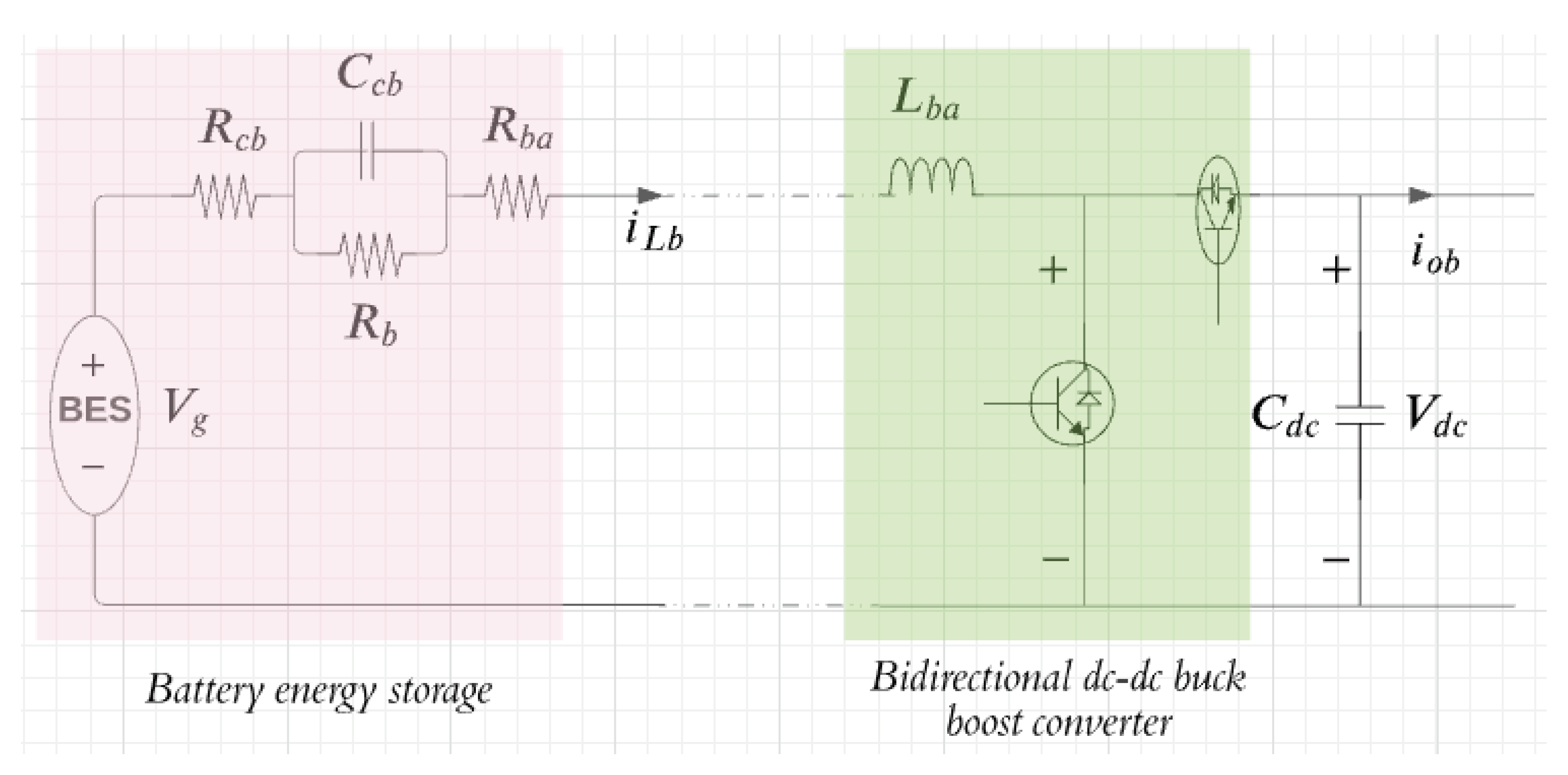
2.2. Mathematical Model of the Battery Energy Storage System

Figure 3 shows a circuit diagram of the battery energy storage system which is connected to the common DC-bus through the bidirectional DC-DC buck-boost voltage source converter. The output voltage across C c b is v c b , and the internal resistance is R b a . The input current of the bidirectional DC-DC buck-boost converter through inductor L b a is i L b , and the output voltage is V d c across the DC-link capacitor C d c . The output current of the converter is i o b , which is bidirectional. The other components of the battery are v g , R b , R b c , and C c b those details can be found in [19].
The mathematical model of the DC-bus connected solar photovoltaic generation associated battery energy storage system can be obtained as follows from Figure 3:
d v c b d t = 1 C c b i L b v c b R b d i L b d t = 1 L b a v g i L b R c b + R b a v c b m b a v d c d v d c d t = 1 C d c m b a i L b i o b
where m b a and v d c are the switching input and the control objective of the bidirectional DC-DC buck-boost voltage source converter, correspondingly.

Generalized Dynamical Model of Photovoltaic and Battery Energy Storage System

From both characteristics, the dynamical model of the common DC-link-connected solar photovoltaic generation and battery energy storage system are represented through (1) and (2), where the first dynamical states have little effect on stability properties [28]. As a result, the last two dynamical states are provided as entire dynamics of the considered system to control the output voltage. The set of Equations (1) and (2) can be presented as a generalized dynamical model in the following form:
d i i d t = 1 L i v i m i v d c d v d c d t = 1 C d c m i i b i o i
where the subscript i is defined the variables related with the respecting elements of the standalone solar photovoltaic generation and battery energy storage system. For solar photovoltaic generation (pv), and battery energy storage system (ba) with V p v = v p v i p v R p v and V b a = v g i b ( R c b + R b ) v c b .

3. Partial Feedback Linearized Control Scheme for Standalone PV-BES System

Many strategies have been proposed in the literature to control a DC-DC voltage source converter in the distributed generation system. Of these strategies, the feedback linearization plus linear control recently proposed, which is very promising. It is based on the DC-DC voltage source converter dynamical model in the distributed generation system discussed in Section 2 and recalled below.
d i i d t = 1 L i v i n m i v d c d v d c d t = 1 C d c m i i b i o i
The SISO system model (4) can be written in the following nonlinear state-space equation:
d x i d t = f i ( x i ) + g i ( x i ) u i y i = h i ( x i )
where x = [ i i v d c ] T , f ( x ) = v i n L i i o i C d c , g ( x ) = v d c L i i i C d c , u = m i and y = h ( x ) = v d c .
In (5), x is the state vector, u is the input variable, y is the output variable, and the system order n = 2 .

3.1. Determine Relative Degree

The Lie derivative of vector field f ( x ) corresponding to the control objective h = v d c is obtained as follows:
L f h ( x ) = L f v d c = i o i C d c
The Lie derivative of vector field g ( x ) corresponding to the control objective h = v d c is obtained as follows:
L g h ( x ) = L g L f 1 1 v d c = i i C d c
As L g L f 1 1 v d c 0 , as shown above, the relative degree r = 1 for the output function. Thus, the relative degree is r = 1 < n = 2 , and the system (4) is partially linearized with the output y = v d c and synthetic control input v. The input–output mapping from v to y is a single integrator.

3.2. Nonlinear Coordinate Transformation of Linearized System

A new state can be obtained from coordinate transformation which can be written as follows:
z 1 = L f 1 1 h = v d c
The dynamics of newly obtained state from Equation (8) can be written as follows:
d z 1 d t = v
where v is the output DC bus voltage regulator which can be generated by applying a linear control approach that will be discuss in next section.

3.3. Zero Internal Dynamic Stability

From the Equation (4), one of the states of the generalized dynamical model of the DC-DC voltage source converter is not directly linearized by feedback linearization technique. It is crucial to check the stability that the remaining state has not to affect the system stability. Here, it needs to be selected in a defined way that it satisfies
lim t h ( x ) 0 .
this means that h ( x ) = 0 at steady state. For which
d z 1 d t = 0
and z 2 = β ( x ) is the nonlinear function which can be represented the remaining state and able to satisfy the following conditions:
L g β ( x ) = 0
Condition (12) can be satisfied if
β ( x ) = 1 2 L i i i 2 + 1 2 C d c V d c 2
The dynamics of Equation (13) become as follows:
β ( x ) x = L f i β ( x ) = v i n i i v d c i o i = P i n P o i
where the input power of the generalized DC-DC voltage source converter is P i n = v i n i i and the output power is P o i = v d c i o i . Due to the ideal or lossless condition, P i n = P o i , Equation (14) can be shortened as follows:
β ( x ) x = 0
The internal dynamics have not affected the stability issue of the DC-DC voltage source converter’s generalized model. As a result, a partial feedback linearized control law can develop as the following subsection.

3.4. Feedback Linearized Control Law Formulation

The feedback linearized control law can be written as follows [28]:
u = v L f r h ( x ) L g L f r 1 h ( x )
Partial feedback linearized control law of normalized DC-DC converter become
m = C d c v + i o i i i
In Equation (17), all elements are either measurable or can be formulated regarding measured variables except linear control input v. A linear control technique can be generated the control input v.

3.5. Transfer Function of Linearized System

The Laplace transformation of (9) is obtained as
V d c ( s ) = 1 s V ( s )
After further simplification, (18) can be written as
V d c ( s ) V ( s ) = 1 s
The output voltage V d c ( s ) of the generalized DC-DC voltage source converter is needed to track their desire V r ( s ) , so the linear control input V ( s ) can be generated as
V s = K ( s ) E ( s )
where K ( s ) is the controller in the Laplace domain and E ( s ) is the Laplace transform of e ( t ) = v r ( t ) v d c ( t ) . The feedback linearized model of the system is G ( s ) = 1 s . The Laplace function of sensitivity and complementary sensitivity corresponding linearized plant G ( s ) and linear controller K ( s ) can be obtained as
S s = 1 1 + G ( s ) K ( s ) T s = G ( s ) K ( s ) 1 + G ( s ) K ( s )
The system output V d c ( s ) and the steady-state error E ( s ) are proportional to the complementary sensitivity transfer function T ( s ) and the sensitivity transfer function S ( s ) , respectively. These can be written as
V d c ( s ) = T ( s ) V r ( s ) E ( s ) = S ( s ) V r ( s )
where V r is a constant value of the desire voltage. To achieved the desire voltage V r and minimized steady-state error a robust H mixed-sensitivity ( S ( s ) & T ( s ) ) loop-shaping controller is proposed which can be generated unmeasurable variable V.

4. Robust Controller Design for Partially Linearized Standalone PV-BES System

4.1. Uncertainty Modeling

The parameter variation is one of the common mismatches between actual and mathematical model of any system and it is essential to address for design a good controller. Including parameter variation, the dynamical model (4) of the system becomes
d x d t = [ f ( x ) + Δ f ( x ) ] + [ g ( x ) + Δ g ( x ) ] u y = h ( x )
where the parameter variation is denoted as Δ . The dynamical model of the generalized distributed DC generation system including parameters uncertainties becomes
d i i d t = α 1 v i n α 1 m v d c d v d c d t = α 2 m i L α 2 i o
where α i = μ i + Δ μ i , μ 1 = 1 L i , μ 2 = 1 C d c , Δ μ 1 = 1 ( L i + Δ L i ) L i ( L i + Δ L i ) , and Δ μ 2 = 1 ( C d c + Δ C d c ) C d c ( C d c + Δ C d c ) . In the presence of uncertainties, the system can be represented as
d Δ i i d t d Δ v d c d t = Δ μ 1 v i n Δ μ 2 i o + Δ μ 1 v d c Δ μ 2 i L m
To satisfy the robust control criteria according to parameter variations, the structure of uncertainties should fulfill the following condition:
Δ f ( x ) a n d Δ g ( x ) s p a n g ( x )
If this matching condition holds, the following criteria will be true:
ω ¯ r = ρ
where r, ρ , and ω ¯ are relative degree of the normalized plant, f ( x ) , and g ( x ) , correspondingly. Regarding matching the uncertainties of the plant, ρ should be equal to relative degree r as follows:
L Δ f h ( x ) = Δ μ 2 i o
The ω ¯ = 1 , corresponding to the output h ( x ) , which will happen if Δ f ( x ) value is positive. The uncertainty of the vector field Δ g ( x ) will match if the subsequent requirement holds:
L Δ g h ( x ) = Δ μ 2 i i 0
Due to such types of situation, the feedback linearization of the uncertain system can be written as
d z d t = [ f ( x ) + Δ f ( x ) ] + [ g ( x ) + Δ g ( x ) ] u
The feedback linearized model of the generalized distributed DC generation system, including uncertainties, is as follows:
d v d c d t = v Δ μ 2 i o + Δ μ 2 i i m
Substituting Equation (18) into Equation (31) can be simplified as follows:
d v d c d t = v 1 + Δ μ 2 μ 2
Assuming = 1 + Δ μ 2 μ 2 , Equation (32) can be simplified as follows:
d v d c d t = v
Equation (33) becomes a Laplace transformation:
V d c ( s ) = s V ( s )
Considering the fact that the measurement output voltage of the common DC bus has been affected by measurement noise, Equation (34) can be written as
V d c ( s ) + N ( s ) = s V ( s )
where N ( s ) is the measurement noise.

4.2. Noise Decoupling Capability of Designed Partial Feedback Linearized Controller

The feedback linearized control scheme can be decoupled the effect of noise. With consideration of exogenous noises, the standard nonlinear dynamical model (5) becomes
d x d t = f ( x ) + g i ( x ) u + D ( x ) p y i = h i ( x i )
where p is the noise input and D ( x ) is the vector field of noise.
To provide reliability on feedback linearization scheme that has been noise decoupling capability, the value of control input m from Equation (17) is substituted into Equation (36). Therefore, Equation (36) becomes
d x d t = f ( x ) + g ( x ) v L f r h ( x ) L g L f r 1 h ( x ) + D ( x ) p
When v = 0 , then Equation (37) can be written as
d x d t = f ( x ) g ( x ) c ( x ) + D ( x ) p
where c ( x ) = L f r h ( x ) L g L f r 1 h ( x ) . In the steady-state operation, the dynamics of state becomes zero, d x d t = 0 . As a result, Equation (38) can be written as
D ( x ) p = g ( x ) c ( x ) f ( x )
After substituting the value of c i , f i , and g i into Equation (39), Equation (39) can be written as
D ( x ) p = v d c L i i i C d c i o i i i v i n L i i o i C d c
After simplifying, (40) becomes
D ( x ) p = v d c L i i o i i i v i n L i 0
From the above equation, it is clear that the linearized part is decoupled from the noise.

4.3. Mixed-Sensitivity-Based Robust H Loop-Shaping Controller Design

Mixed-sensitivity-based H loop-shaping controller design is depended on the shape of sensitivity transfer function S(s) and complementary sensitivity transfer function T(s). The selection of weight functions corresponding to S(s) and T(s) are played an important role, which can be picked to fulfill the following conditions:
| | S ( s ) + T ( s ) | | 1 , a | | W S ( s ) S ( s ) | | < 1 , b | | W T ( s ) T ( s ) | | < 1 , c | | 1 W S ( s ) | | > | | S ( s ) | | , d | | 1 W T ( s ) | | > | | T ( s ) | | , e
A traditional technique for selecting weight function meets the expectations as a high-pass and low-pass filter corresponding to the sensitivity transfer function S(s) and complementary sensitivity transfer function T(s). Based on this classical approach, both weight functions can be developed as follows:
W S s = k s / M + ω 0 s + ω 0 A W T s = g s + ω 0 / M A s + ω 0
The partial feedback linearized plant with 10% parameter variation is considered as G ( s ) = s 0.91 ( s + 0.001 ) and the weighting functions become
W S s = 0.84615 ( s + 6.5 ) ( s + 5 × 10 4 ) W T s = 5900 ( s + 3.846 ) ( s + 5 × 10 4 )
The controller K(s) that enforces can be easily computed by applying MATLAB command K ( s ) = m i x s y n ( G , W S , [ ] , W T ) as follows:
K i s = 4.078 × 10 7 s 2 + 2.039 × 10 12 s + 2.054 × 10 9 s 3 + 6.872 × 10 10 s 2 + 6.617 × 10 13 s + 3.266 × 10 10
The sigma plots of the weighting function and sensitivity function have been shown in Figure 4, similar to the lead–lag compensator. The gain value of the is increases at the low frequency, which is provided better disturbance rejection at the same the loop gain of sensitivity function S(s) is inversely proportional to the sensitivity weighting function.
Each condition of the equation (42) are fulfilled, which is clear from Table 1. The gain value is decreased at low frequency, which can be provided with better reference tracking capability. The loop gain of the complementary sensitivity transfer functions T ( s ) is inversely proportional to the complimentary sensitivity weighting function. The crossover frequency of the T ( s ) is significantly larger than the S ( s ) and different weighting functions, the resultant transfer function from W T ( s ) is proper.

5. Performance Evaluation of Standalone PV-BES System

To implemented nonlinear partial feedback linearized control law for the normalized DC-DC power electronic converter is required the measurement value of DC bus voltage and input and output current of the converter. The implementation layout of a proposed control scheme presents in Figure 5 where the nonlinear controller inputs are the output of the linear controller and the input and output current of the DC-DC converter. The difference between the measured and recommended output voltages are treated into the robust mixed-sensitivity loop-shaping controller to achieve the unmeasurable V(s). This unmeasurable V(s) is merged with the proposed nonlinear control law to get the desired switching input of DC-DC converters of the standalone hybrid PV-BES system. The designed controller is worked based on the local information of individual components in the hybrid standalone PV-BES system.
The performance of the proposed robust nonlinear controller has been illustrated on the test standalone hybrid PV-BES system. The test standalone hybrid PV-BES system has a PV power generator with 26 kW output power and 280 nominal DC voltage. In the PV generator, 12 strings are parallel connected, and eight cells are connected in series modules per string. The current and voltage at the maximum power point are 35 V and 7.72 Amp, respectively. A DC-DC boost PEI (with L = 8 mH) has been used between output voltage 240 V of solar PV panel and expected output DC bus voltage 500 V. The value of the DC-link capacitor is 5 mF. The BES unit has been connected to the same DC-link capacitor through a bidirectional DC-DC buck-boost converter (L = 10 mH). It is a nickel-cadmium battery whose nominal output voltage is 320 V, the rated capacity is 20 Ah, the initial state-of-charge is 85%, and the battery response time is 30 s. A constant DC load is connected at the DC bus, which power rating is 6.25 kW. The proposed DC microgrid has no contacts with the utility grid, i.e., it runs in the islanded mode.
The proposed robust nonlinear controller’s performance is illustrated over a massive change at operating points to validate the argue of operating point independence of the partial feedback linearized (PFBL) controller. The robustness of the proposed PFBL- H controller has been compared to the existing PFBL-PI controller. The stability enhancement capability of H over the PI controller is investigated, and these operating point variations have been classified by the following categories.

5.1. Proposed Controller Performance Investigation under Generation Change

To illustrate the accomplishment of the designed robust PFBL controller under generation change, a constant DC load is connected at the DC bus that is considered. At the beginning study of such a case, a solar PV panel has generated a rated power of 26 kW. On the other hand, the demand power is connected in the common DC bus with a rating of 6.25 kW. As a result, an extra 19.75 kW generated power from the solar PV panel went into the battery as storage power during 0 s to 2 s. At 2 s, the power generation from the PV panel is suddenly reduced to 18 kW from 26 kW due to the solar irradiation changes. Consequently, the rate of energy storage in the battery has become 11.75 kW from 19.75 kW.
Figure 6 has shown that the BES system’s storage power has been affected at 2 s due to the sudden change of generation from the solar PV panel. The transient effect on the battery energy storage and the DC bus voltage is relatively less with the proposed robust PFBL controller over the existing PFBL controller. From Table 2, the settling time and overshoot of measured responses are higher for the existing controller. The large settling time and large overshoot of any system may be responsible for pausing into instability reason.

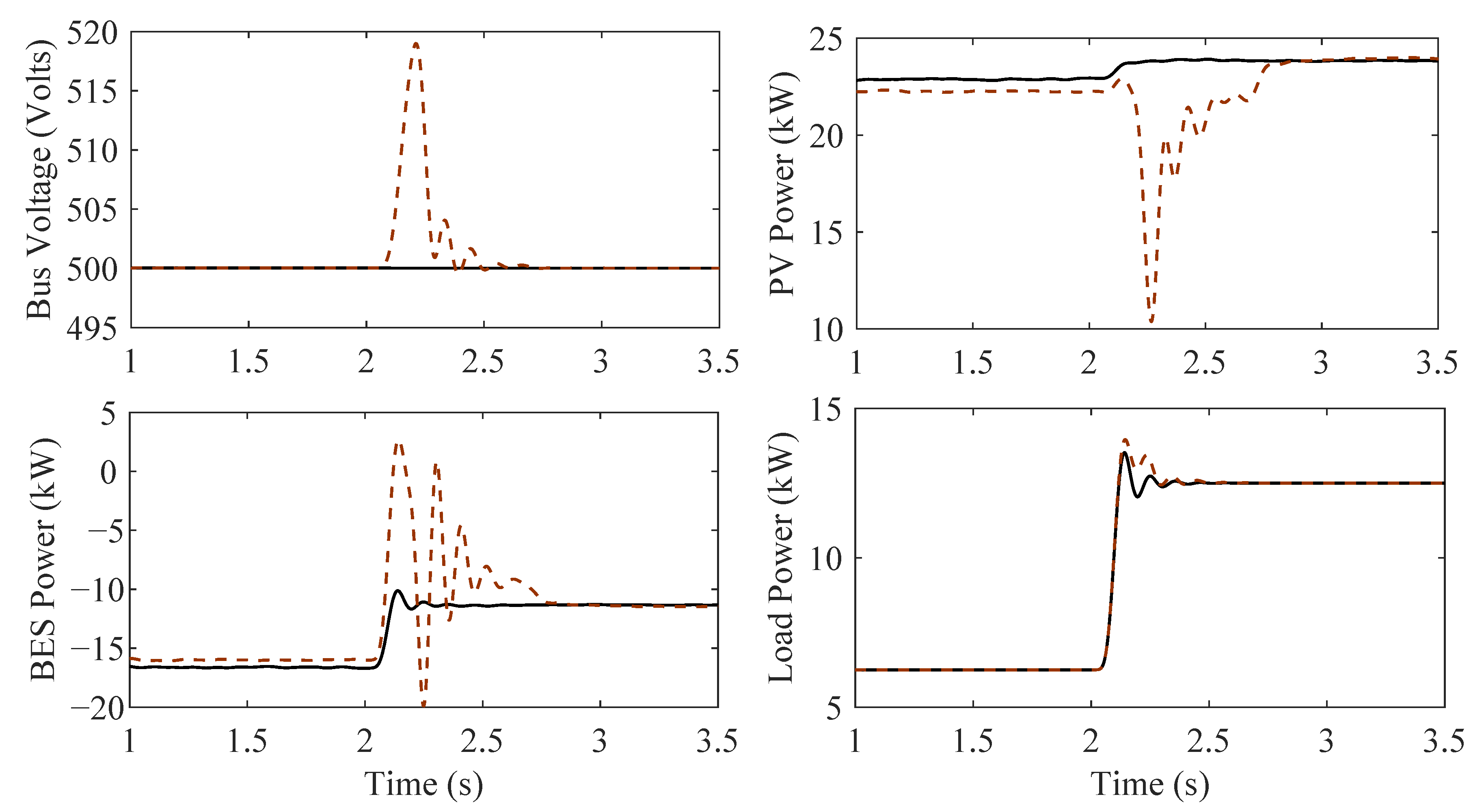
5.2. Proposed Controller Performance Investigation under Load Variation

In this case, the study considered that the solar PV panel had been generated constant power, and the demand power at common DC bus is varied. At the beginning study of such a case, the solar PV panel has generated a rated power of 26 kW. On the other hand, the demand power is connected in the common DC bus with a rating of 6.25 kW. As a result, an extra 19.75 kW generated power from the solar PV panel went into the battery as storage power during 0 s to 2 s. At 2 s, the common DC bus’s demand power suddenly increases from 6.25 kW to 12.5 kW due to the equal demand connected in the common DC bus. Consequently, the rate of energy storage in the battery has become 7.25 kW from 19.75 kW.
Figure 7 has shown that the PV generation and battery energy storage power have been affected at 2 s due to the sudden demand power changes at the common DC bus. The transient effect on the battery energy storage and PV generation power and the DC bus voltage is more affected with the existing PFBL controller over the proposed robust PFBL controller. The settling time and overshoot of measured responses are higher for the existing controller, clear from Table 3. The greater settling time and large overshoot of any system may be responsible for pausing into instability reason.

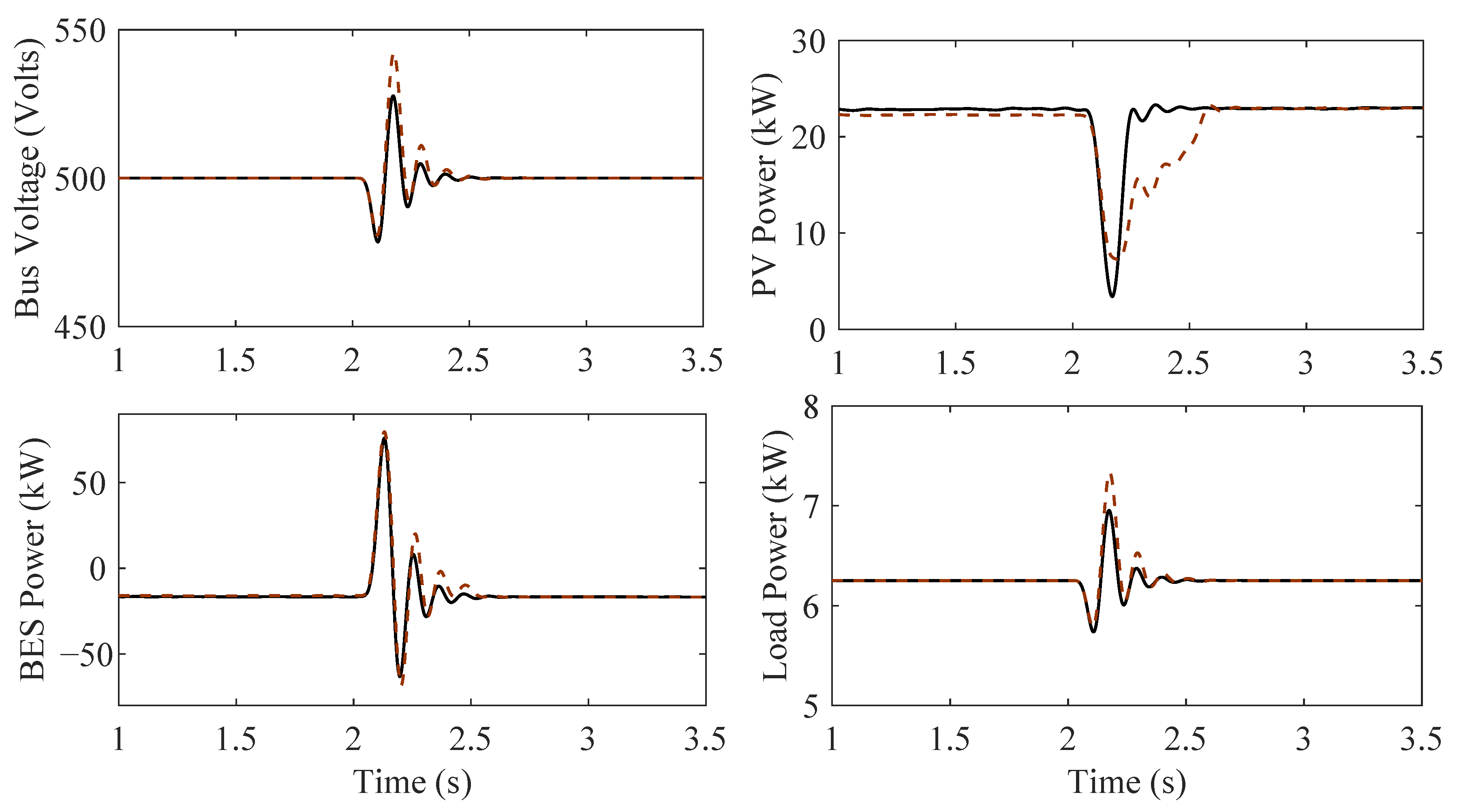
5.3. Proposed Controller Performance Investigation under Parameter Variation

The parameter variation is a common problem in the control system study, which can be occurred for the mismatch between the actual system and mathematical model. Furthermore, it can happen corresponding to the extensive time duration. This subsection has been trying to present that pictorial view of Section 4.1 (uncertainty modeling). In this case study, the standalone hybrid PV-BES system worked with a nominal parameter during 0 s to 2 s. At 2 s, it is considered that the DC-link capacitor has been changed 10%.
Consequently, the generated power from the solar PV panel and the storage power into the battery both are heavily affected at the same time that is clear from Table 4 and Figure 8. In this situation, the proposed robust PFBL- H controller is given a better voltage and power profile over the existing PFBL-PI controller.

5.4. Proposed Controller Performance Investigation under Measurement Noise

In a feedback or closed-loop system, the measured information can be corrupted by measuring the implemented controller’s noise. The noisy measurement signal is highly responsible for reduced the performance of any feedback system. The white Gaussian noise has been injected into the output DC bus voltage with 0.01 amplitude to investigate the robustness of the designed robust PFBL controller under measurement noise.
The measured output DC voltage is affected at 2 s by the measurement noise. As a result, the solar PV panel’s output power and the battery’s storage power are badly affected in Figure 9 and Table 5; those responses have been illustrated. The proposed control scheme provides faster steady-state responses and a smaller overshoot than the existing controller.

6. Conclusions

This paper presents nonlinear partial feedback linearized control scheme with a mixed-sensitivity-based robust H loop-shaping controller as a replacement of the conventional P I controller of the same control scheme. A parametric uncertainty model is developed for the normalized DC-DC voltage source converter in the standalone solar PV with an energy storage system. The designed robust H controller is provided more disturbance rejection capability and stability margin, which are investigated by quantitative and qualitative analysis. The designed controller’s performance is illustrated under four different common worst cases where that controller performs much better than the compared existing controller. In future, the proposed robust partial feedback linearized controller can be implemented in the microgrid system to enhance transient stability and robustness.

Author Contributions

Conceptualization, H.P.; Formal analysis, M.R.M.; Methodology, M.R.M.; Supervision, H.P.; Validation, M.R.M.; Writing—original draft, M.R.M.; Writing—review and editing, H.P. All authors have read and agreed to the published version of the manuscript.

Funding

This research received no external funding.

Conflicts of Interest

The authors declare no conflict of interest.

References

  1. Salah, W.A.; Abuhelwa, M.; Bashir, M.J. The key role of sustainable renewable energy technologies in facing shortage of energy supplies in Palestine: Current practice and future potential. J. Clean. Prod. 2020, 293, 125348. [Google Scholar] [CrossRef]
  2. Javed, K.; Ashfaq, H.; Singh, R.; Hussain, S.; Ustun, T.S. Design and performance analysis of a stand-alone PV system with hybrid energy storage for rural India. Electronics 2019, 8, 952. [Google Scholar] [CrossRef] [Green Version]
  3. Lohmann, G.M. Irradiance variability quantification and small-scale averaging in space and time: A short review. Atmosphere 2018, 9, 264. [Google Scholar] [CrossRef] [Green Version]
  4. Döşoğlu, M.K.; Arsoy, A.B. Transient modeling and analysis of a DFIG based wind farm with supercapacitor energy storage. Int. J. Electr. Power Energy Syst. 2016, 78, 414–421. [Google Scholar] [CrossRef]
  5. Ma, T.; Yang, H.; Lu, L. Development of hybrid battery–supercapacitor energy storage for remote area renewable energy systems. Appl. Energy 2015, 153, 56–62. [Google Scholar] [CrossRef]
  6. Rajshree, B.; Manan, S. Solar photovoltaic energy in India: Business feasibility study and analogy of policies. Int. J. Energy Water Resour. 2021, 1–12. [Google Scholar] [CrossRef]
  7. Takruri, M.; Farhat, M.; Barambones, O.; Ramos-Hernanz, J.A.; Turkieh, M.J.; Badawi, M.; AlZoubi, H.; Abdus Sakur, M. Maximum Power Point Tracking of PV System Based on Machine Learning. Energies 2020, 13, 692. [Google Scholar] [CrossRef] [Green Version]
  8. Lai, C.S.; Locatelli, G.; Pimm, A.; Wu, X.; Lai, L.L. A review on long-term electrical power system modeling with energy storage. J. Clean. Prod. 2020, 280, 124298. [Google Scholar] [CrossRef]
  9. Saadeh, O.; Rabady, R.; Melhem, M.B. New effective PV battery charging algorithms. Sol. Energy 2018, 166, 509–518. [Google Scholar] [CrossRef]
  10. Weniger, J.; Tjaden, T.; Bergner, J.; Quaschning, V. Dynamic mismatch losses of grid-connected PV-battery systems in residential buildings. J. Energy Storage 2017, 13, 244–254. [Google Scholar] [CrossRef]
  11. El-Shahat, A.; Sumaiya, S. DC-Microgrid System Design, Control, and Analysis. Electronics 2019, 8, 124. [Google Scholar] [CrossRef] [Green Version]
  12. Mohamed, Y.A.R.I.; El-Saadany, E.F. Adaptive decentralized droop controller to preserve power sharing stability of paralleled inverters in distributed generation microgrids. IEEE Trans. Power Electron. 2008, 23, 2806–2816. [Google Scholar] [CrossRef]
  13. Diaz, N.L.; Dragičević, T.; Vasquez, J.C.; Guerrero, J.M. Intelligent distributed generation and storage units for DC microgrids—A new concept on cooperative control without communications beyond droop control. IEEE Trans. Smart Grid 2014, 5, 2476–2485. [Google Scholar] [CrossRef] [Green Version]
  14. Ray, P.K.; Das, S.R.; Mohanty, A. Fuzzy-controller-designed-PV-based custom power device for power quality enhancement. IEEE Trans. Energy Convers. 2018, 34, 405–414. [Google Scholar] [CrossRef]
  15. Sahoo, S.; Mishra, S.; Jha, S.; Singh, B. A cooperative adaptive droop based energy management and optimal voltage regulation scheme for DC microgrids. IEEE Trans. Ind. Electron. 2019, 67, 2894–2904. [Google Scholar] [CrossRef]
  16. Behjati, H.; Davoudi, A.; Lewis, F. Modular DC–DC converters on graphs: Cooperative control. IEEE Trans. Power Electron. 2014, 29, 6725–6741. [Google Scholar] [CrossRef]
  17. Yang, J.; Jin, X.; Wu, X.; Acuna, P.; Aguilera, R.P.; Morstyn, T.; Agelidis, V.G. Decentralised control method for DC microgrids with improved current sharing accuracy. IET Gener. Transm. Distrib. 2017, 11, 696–706. [Google Scholar] [CrossRef]
  18. Tah, A.; Das, D. An enhanced droop control method for accurate load sharing and voltage improvement of isolated and interconnected DC microgrids. IEEE Trans. Sustain. Energy 2016, 7, 1194–1204. [Google Scholar] [CrossRef]
  19. Tahim, A.P.; Pagano, D.J.; Ponce, E. Nonlinear control of dc-dc bidirectional converters in stand-alone dc microgrids. In Proceedings of the 2012 IEEE 51st IEEE Conference on Decision and Control (CDC), Maui, HI, USA, 10–13 December 2012; pp. 3068–3073. [Google Scholar]
  20. Ohirul Qays, M.; Buswig, Y.; Hossain, M.L.; Abu-Siada, A. Active Charge Balancing Strategy Using the State of Charge Estimation Technique for a PV-Battery Hybrid System. Energies 2020, 13, 3434. [Google Scholar] [CrossRef]
  21. Ko, S.T.; Park, S.S.; Lee, J.H. Regenerative Battery Charging Control Method for PMSM Drive without a DC/DC Converter. Electronics 2019, 8, 1126. [Google Scholar] [CrossRef] [Green Version]
  22. Roy, T.K.; Mahmud, M.A.; Oo, A.M.T.; Haque, M.E.; Muttaqi, K.M.; Mendis, N. Nonlinear adaptive backstepping controller design for islanded DC microgrids. IEEE Trans. Ind. Appl. 2018, 54, 2857–2873. [Google Scholar] [CrossRef]
  23. Hernández-Márquez, E.; Avila-Rea, C.A.; García-Sánchez, J.R.; Silva-Ortigoza, R.; Silva-Ortigoza, G.; Taud, H.; Marcelino-Aranda, M. Robust tracking controller for a DC/DC Buck-Boost converter–inverter–DC motor system. Energies 2018, 11, 2500. [Google Scholar] [CrossRef] [Green Version]
  24. Mahmud, M.R. Novel Robust Controller Design to Enhance Transient Stability of Power Systems. Master’s Thesis, Swinburne University of Technology, Hawthorn, Australia, 2017. [Google Scholar]
  25. Mahmud, M.; Pota, H. Robustness analysis of h controller for feedback linearized model of grid connected inverter. In Proceedings of the 2018 IEEE International Conference on Power Electronics, Drives and Energy Systems (PEDES), Madras, India, 18–21 December 2018; pp. 1–6. [Google Scholar]
  26. Mahmud, R.; Hossain, M.A.; Pota, H. Robust Nonlinear Controller Design for Islanded Photovoltaic System with Battery Energy Storage. In Proceedings of the 2020 IEEE International Conference on Power Electronics, Smart Grid and Renewable Energy (PESGRE2020), Cochin, India, 2–4 January 2020; pp. 1–6. [Google Scholar]
  27. Mahmud, M.A.; Roy, T.K.; Islam, S.N.; Saha, S.; Haque, M.E. Nonlinear decentralized feedback linearizing controller design for islanded dc microgrids. Electr. Power Compon. Syst. 2017, 45, 1747–1761. [Google Scholar] [CrossRef]
  28. Mahmud, M.A.; Roy, T.K.; Saha, S.; Haque, M.E.; Pota, H.R. Robust nonlinear adaptive feedback linearizing decentralized controller design for islanded dc microgrids. IEEE Trans. Ind. Appl. 2019, 55, 5343–5352. [Google Scholar] [CrossRef]
Figure 1. Typical view of a standalone hybrid PV-BES system.
Electronics 10 00772 g001
Figure 2. Circuit diagram of DC-bus connected solar photovoltaic panel through DC-DC boost converter.
Electronics 10 00772 g002
Figure 3. Circuit diagram of DC-bus connected battery energy storage through bidirectional DC-DC buck-boost converter.
Electronics 10 00772 g003
Figure 4. Sigma plot of different sensitivity and weighting functions.
Electronics 10 00772 g004
Figure 5. Implementation block diagram of proposed partial feedback linearized control scheme with conventional PI and robust H controller.
Electronics 10 00772 g005
Figure 6. Bus voltage and different power responses under generation change.
Electronics 10 00772 g006
Figure 7. Bus voltage and different power responses under load variation.
Electronics 10 00772 g007
Figure 8. Bus voltage and different power responses under parameter variation.
Electronics 10 00772 g008
Figure 9. Bus voltage and different power responses under measurement noise.
Electronics 10 00772 g009
Table 1. H norm value of weighting and sensitivity functions.
Conditions H Norm Values
(42-a) 1 1.0410
(42-b) 0.9787 < 1
(42-c) 0.6636 < 1
(42-d) 1.1818 > 1.0017
(42-e) 2.2034 > 1.0180
Table 2. Quantitative comparison between proposed and existing controller under generation change.
Comparative IssuesControllerBus VoltagePV PowerStorage PowerLoad Power
Under or overshoot (%) P F B L H 0.000.000.000.00
P F B L P I 2.6033.035.04.80
Settling time (s) P F B L H 0.000.000.000.00
P F B L P I 0.300.400.400.30
Table 3. Quantitative comparison between proposed and existing controller under load variation.
Comparative IssuesControllerBus VoltagePV PowerStorage PowerLoad Power
Under or overshoot (%) P F B L H 0.000.000.008.00
P F B L P I 4.0052.067.012.0
Settling time (s) P F B L H 0.000.000.000.20
P F B L P I 0.250.700.700.25
Table 4. Quantitative comparison between proposed and existing controller under parameter variation.
Comparative IssuesControllerBus VoltagePV PowerStorage PowerLoad Power
Under or overshoot (%) P F B L H 5.0085.035016.0
P F B L P I 8.0069.036024.0
Settling time (s) P F B L H 0.250.300.300.30
P F B L P I 0.30.500.400.40
Table 5. Quantitative comparison between proposed and existing controller under measurement noise.
Comparative IssuesControllerBus VoltagePV PowerStorage PowerLoad Power
Under or overshoot (%) P F B L H 1.0043.094.048.0
P F B L P I 3.0035.013113.0
Settling time (s) P F B L H 0.200.300.350.30
P F B L P I 0.20.450.500.30
Publisher’s Note: MDPI stays neutral with regard to jurisdictional claims in published maps and institutional affiliations.

