Article

Influence of Aircraft Power Electronics Processing on Backup VHF Radio Systems

1
Faculty of Military Technology, University of Defence, 66210 Brno, Czech Republic
2
MOVEJ Analytics, Dayton, OH 45433, USA
*
Author to whom correspondence should be addressed.
Electronics 2021, 10(7), 777; https://doi.org/10.3390/electronics10070777
Submission received: 1 March 2021 / Revised: 15 March 2021 / Accepted: 20 March 2021 / Published: 25 March 2021
(This article belongs to the Section Industrial Electronics)

Abstract

:
The paper describes the influence of power electronics, energy processing, and emergency radio systems (ERS) immunity testing on onboard aircraft equipment and ground stations providing air traffic services. The implementation of next-generation power electronics introduces potential hazards for the safety and reliability of aircraft systems, especially the interferences from power electronics with high-power processing. The paper focuses on clearly identifying, experimentally verifying, and quantifiably measuring the effects of power electronics processing using switching modes versus the electromagnetic compatibility (EMC) of emergency radio systems with electromagnetic interference (EMI). EMI can be very critical when switching power radios utilize backup receivers, which are used as aircraft backup systems or airport last-resort systems. The switching power electronics process produces interfering electromagnetic energy to create problems with onboard aircraft radios or instrument landing system (ILS) avionics services. Analyses demonstrate significant threats and risks resulting from interferences between radio and power electronics in airborne systems. Results demonstrate the impact of interferences on intermediate-frequency processing, namely, for very high frequency (VHF) radios. The paper also describes the methodology of testing radio immunity against both weak and strong signals in accordance with recent aviation standards and guidance for military radio communication systems in the VHF band.

1. Introduction

Safety-critical avionics situations arise when a radio signal is unavailable for pilots who need commands and information for their flight as well as for air traffic controllers (ATC) who provide air traffic services in their airspace. The circumstances can be more serious during an approach to landing or in critical conditions when pilots and ATCs must reliably communicate beyond standard phraseology. Such a radio signal degradation from avionics equipment, known as electromagnetic interference (EMI), can directly decrease safety in air traffic transport, surveillance, and travel.
Current avionics power systems implement power electronics devices for energy generation, conversion, and distribution over electrical networks. Power electronics switching circuits can improve the efficiency performance of modern airborne power systems. The number of switched power elements in airborne systems is expected to steeply rise in the next decade, where every subsystem or device working as a part of an electrical or electronic aircraft system already contains or will contain power electronics. An important recent power technology is switching converters based on pulse-width modulation (PWM) switching. These PWM converters are one of the fastest developing technologies that are used in the modern aircraft using electric drives. Power electronics circuits for electric drives allow the control of the directional flow of both data and power between sources and consumers backward and forward in an entire aircraft power system. Two main factors participate in the power switching improvement: (1) recent high-voltage devices based on the SiC (silicon carbide) technology permit more dynamical and reliable control of the energy flow; and (2) significantly more accurate real-time monitoring of the aircraft system power use [1,2].
The implementation of power electronics, including the power switching sources in real aeronautical systems, needs to comply with current aeronautical standards and their implementation directives. The probability of occurrence of an electromagnetic compatibility (EMC) hazard is very low, but the requirement highlights a risk assessment of induced signal susceptibility such as category Z of 1800 volts × meters [3]. The RTCA DO-160 standard contains basic EMC requirements and EMC testing on aircraft and general test procedures. Hence, this paper brings to attention several potential EMC threats caused by a switching power supply and their effects on the reliability of, for example, the aeronautical backup system with very high frequency (VHF) services, which are not currently well described in aeronautical standards [3].

1.1. Overview of Aeronautical Radio Backup Systems

As backup power systems are inseparable components in many onboard and off-board aircraft technologies, there is a need to understand the impacts on system performance. Some backup sources are similar to the main systems, but the onboard systems are subject to placement and weight restrictions.
As for radio equipment, there is the main communication very high frequency (COM-VHF) radio (see Figure 1), working in the bandwidth of 117–137 (144) MHz. The communication signal is typically designed using software-defined technology, where radio frequency (RF) blocks are efficiently shielded from interferences coming from other electronic devices; however, such shielding can increase weight, size, and other power supply requirements (filtering, signal processing, etc.), in comparison to electronic devices working in environments without any interferences. A backup VHF communication receiver is typically built as a simple or double-heterodyne receiver in a low-dimension RF design. In addition, there are emergency radio devices in military aviation as a part of a pilot’s survival kit. These radio receivers are based on regenerative reception, having simple designs and compact dimensions. Likewise, the radio receivers must survive a pilot’s ejection, carry their own power source, and operate in very extreme conditions [2].
In this paper, an example of electromagnetic interference (EMI) produced by power electronics versus the VHF radio systems is presented. The airborne VHF/ultra-high frequency (UHF) main backup COM radios LUN-3520 and LUN-3524 were tested. Both radios are based on the same technology. In addition, two other devices were experimentally verified in the instrument landing system (ILS) receiver that are also based on the VHF/UHF frequency bandwidth: (1) VHF localizer from 108.10 MHz to 111.95 MHz, and (2) the UHF glideslope signals are in the 326–335 MHz range that provide the pilot with course guidance to the runway centerline. In aviation, the localizer and glideslope beacons operate with two signals that are transmitted at 40 ILS channels with two modulation signals of 90 Hz and 150 Hz. The typical VHF radio systems are shown in Figure 1.
The receiver LUN3520 is built as a heterodyne receiver with an intermediate frequency of 21 MHz in the VHF bandwidth and a double-heterodyne receiver in the UHF bandwidth, with two intermediate frequencies (IF) of 56 MHz and 21 MHz. The reason why the double-heterodyne is utilized is the suppression of mirror frequencies. For example, the received signal frequency is let through by normal processing, but an amplitude modulation (AM) demodulator extracts the signal from the carrier wave and the low-frequency (LF) power amplifier [2,4].
In aeronautics, another example is air traffic controller (ATC) radio systems at the air traffic service unit (ATSU). There is the communication system providing aeronautical mobile services, consisting of VHF/UHF transmitters, receivers, backup radios, and last-resort emergency systems. The composition is given by standards and regulations published by an authorized aviation authority [4,5,6]. Generally, ATSU communication systems are spatially divided into transmitting, receiving, and last-resort modes. When in receiving mode, the radio is not placed in technical rooms at the ATSU but rather stands alone so as not to be disturbed by other ATSU systems and consequently decrease the sensitivity of the radios. With the isolation conditions, the receivers can reach the sensitivity of −93 dBm (measured in accordance with [5,6]). In the ATSU communication system, there are two levels of backup. The first is the “N + 1 backup, where the transmitter and receiver have added blocks, which are the same as the main radios. The second level of backup is the last-resort system (LRS) (i.e., direct mode operations or repeater talk-around), which is completely independent from the main power supply, radio devices, and radio management. The LRS system is used when all main ATSU systems, including the power supply, collapse. Although LRS radios are typically based on the same software-defined radio (SDR) technology as the main radio system, LRS radios have common receiving and transmitting components and all the radios are placed in the technical room with other ATC technologies—servers, power electronic devices, universal power supplies (UPSs), pulse sources, etc. Hence, such LRS radios can operate in environments with high levels of EMI [3,5,6,7].

1.2. Overview of Airborne Power Electronics and Power Processing

Aircraft power electronics uses power switching technologies to control the flow of power. Power electronics represents one of the fastest developing technologies towards the integration of electric drives in aircraft systems. They have enormous potential for energy conversion applications to reduce the power density of the electric equipment on board modern aircraft. In addition, high-speed electric drive research may significantly contribute to increasing the power density of electromechanical systems [8,9].
Power electronics on board aircraft uses switching technologies with power devices based on the modern metal–oxide–semiconductor field-effect transistor (MOSFETs) and insulated-gate bipolar transistor (IGBTs) devices based on the silicon carbide (SiC) or gallium nitride (GaN) technology to increase the frequency of power switching. High-speed switching requirements are closely connected to the power density of the power circuits and power losses. The power electronic directly controls the dynamic behavior of the drive, employing typical vector control or direct torque control. However, there is usually no active control of the switching behavior of the power electronic elements implemented in the system, such as the adaptive dead-time controlled by the switched current/voltage or as per EMC requirements. As the power outputs and maximal speeds of electrical drives increase, controlling these parameters is gaining in importance. Moreover, much higher switching frequencies have been made possible by introducing novel power electronic elements based on SiC organ technologies, which makes the problem even more difficult [7,8]. For example, it is well known that the motor electrical losses increase with a higher content of current harmonics. If a typical three-phase alternating current (AC) converter is used instead of the sinusoidal voltage supply, the total motor losses may increase by 5% to 10%. Hence, the effects of EMC compliance are related to both losses and power quality issues. The power quality depends on the content of harmonic components in the voltage produced by PWM AC converters employing various modulation strategies, power electronics technologies, and layout topologies. Power electronics switching produces EMI, which becomes a major problem and makes EMC analysis in various operating modes essential [1,2,8,9].
An electrical power system is shown in Figure 2, which is a simplified representation of the aircraft electrical power system. The primary AC system uses integrated drive generators (IDG) from the aircraft engine and gearbox to get the high speeds required for aircraft use. Modern AC generators produce power up to 100 kVA based on the three-phase concepts to reduce the power density of AC generators. The output of the generator must be constant at 115 VAC 400 Hz, but permanent magnet generators have become prominent because the maximum efficiency is up to 90%, but the output (voltage, frequency) is variable and must be stabilized by power electronics AC-to-AC conversions [8].
Bus power control units may also be used as power converters to set a constant bus voltage of 115 VAC (volts alternating current) at 400 Hz. DC bus systems frequently use the method of power conversion by use of transformer rectifier units (TRUs). TRUs use a transformer to provide the desired 115 VAC to 28 VDC conversions. These transformers are very heavy and bulky, and therefore high-frequency switching transformers (HFT) are used to improve the power density. These HFTs require power electronics to increase the switching frequency up to 20 kHz. In addition, power electronics is necessary for AC or DC electrical drives, as can be seen in Figure 2. For high-power switching, frequencies of ~3 kHz are used. It is evident that the main power processing switching is around 3 kHz power electronic switching [7,8,9].
Power electronics improves the performance of modern airborne power systems. Implementation of power electronics including a “smart grid“ or Internet of Things (IoT) technology in a real airborne system needs to comply with current regulatory standards. Power electronics standards for onboard aircraft systems address safety and reliability hazards from interferences induced by power electronics with a high voltage [8,9]. Current regulations are being carefully considered, and the critical aspects of the implementation have to be clearly identified and analyzed. An example of EMI is presented in Figure 3. The power electronic—DC-to-AC converter with a transformer, which converts a DC voltage of 28 VDC to 115 VAC at 400 Hz—generates unwanted harmonics at multiples of the frequency of the switching signal. These unwanted signals then propagate through the conductive connections (Figure 3a) or are radiated (Figure 3b) by the conductors. Figure 3 presents a clear example of interferences caused by power electronics, which can seriously compromise the functionality and reliability of the avionic devices. Figure 3 also shows the wideband character of interfering power signals, which can be up to MHz frequencies and the interferences can decrease the reliability of onboard aircraft systems, as it will be shown in the rest of this paper.
Every individual design of the power electronic system requires a unique analysis of the EMI among power supplies, distribution of networks, and intended consumers—i.e., avionics and radio systems. The EMI analysis has to define critical frequencies or frequency bands and to set safe limits of the interference levels at those sensitive frequencies for such susceptible devices as RF systems. Practical experiences with a modern avionic system emphasize the importance of monitoring EMC problems [1,3,9].
It is evident that multiple power electronic converters are necessary in future aircraft electronics. The trend has two important downsides: significantly lowering the quality of delivered electric energy and increasing unwanted electromagnetic radiation. The probability of occurrence of an EMC hazard is very low. However, this paper brings to attention several potential threats caused by a switching power supply such as signal noise and frequency disruption. The signal disruption has the potential for onboard aircraft systems safety and reliability hazards, especially interferences with the power supply. The next section provides the critical aspects of the power electronics of aircraft systems.

2. Analysis of Interference Sources on Airborne VHF Systems

Current and future airborne power systems are and will be based on switching components. The power electronics on board aircraft is currently based on Si technology, and the near future will bring SiC technology into onboard power electronics. The basic difference between these technologies is not only the difference in switching frequencies but also in the possible range of interferences with the airborne radio systems. As Si technology mostly influences VHF and the lower part of UHF (ultra-high frequency) radio systems, SiC technology will influence UHF navigation and surveillance systems in aviation [7,10].
A solution to mitigate the interference is to efficiently suppress the mirror frequencies, for signal reception, but there are also parasitic reception channels. The main signal reception is on intermediate frequencies (IF), their multiples, and partial harmonics plus the sum and difference signals of the input frequencies, as all the amplifiers have non-linearity [10]. Reception on such IF frequencies can efficiently suppress not only the strict linear characteristics of used amplifiers but also EMI shielding measurements. However, such measurements require more device space as well as an increase in the device weight. Although shielding materials can bring a high level of suppression of unwanted signals—41 dB or more [11,12]—the shielding spacing in a device consequently increases the device’s dimensions. In Figure 4, there is a comparison between two technologically identical devices. The first one is the solution for the main airborne radio (Figure 4a), where the RF part is completely shielded and also the device is more robust, and the second is an airborne backup radio (Figure 4b), where the shielding is simpler and the complex solution is thinner. Despite the different mechanical dimensions, the main electrical parameters, except EM immunity, are fully comparable.

2.1. Possible Sources of Electromagnetic Interferences

As receivers of airborne radios can operate in very harsh conditions—temperature ranges from −50 °C to 50 °C—there are wide pressure ranges corresponding to pressures at the sea level to pressures at heights of more than ten kilometers (e.g., flight level—FL430 or 43,000 ft) [13,14], from which receivers must also operate in environments with high levels of interferences. From the EMI point of view, receiver electronics of airborne radios are very close to possible electromagnetic disturbance, where the possible sources of such disturbance can be the power electronics in aircraft systems working with high levels of power transmission. Although the voltage level in aircraft systems does not exceed the typical voltage of airborne systems, 115 V/400 Hz—generators, converters, etc.—typical currents can easily reach the values of hundreds of amperes. Secondly, nowadays, onboard electronics work with 28 volts, containing power electronics converters and similar circuits using pulses, which consequently generate wide-spectrum signals. Both these sources and the spatial neighborhood of the aircraft systems can cause two basic types of EMI in the VHF bandwidth. The first one is the increased level of EMI sensor noise, where such noise can cause the perceptible degradation of sensitivity or squelch activation. As for navigation receivers, where very high frequency omni-directional range (VOR), instrument landing system-localizer (ILS/LOC), and marker (MKR) beacon receivers work in the VHF bandwidth, such interference can cause an increased error in navigation measurement or unintended signalization (MKR optical signalization). The second way of disruption is EMI on a specific frequency. An airborne radio has many unwanted receiving effects resulting from imperfect shielding, non-linear characteristics of amplifiers, use of IF frequencies, and solutions for squelch circuits.
An example shape of a disturbing signal fully corresponds to the standards [3,12]. A complex overview of the disturbing signal affecting the VHF backup communication or navigation system is shown in Figure 5. The figure shows the interference with an 822 Hz disturbing signal.
Figure 5 shows the example of an EMI with the burst signal, disturbing an airborne backup radio. The burst signal generator simulates airborne power electronics systems on board the aircraft. Real onboard power electronics contains power generators and various converters: AC-to-AC, AC-to-DC, and motor drivers. Most of them are based on pulse switching, currently mostly using Si technology, and expanding to SiC technology, where the pulse width in SiC systems can be up to four times shorter in comparison to traditional Si systems [7,9].

2.1.1. Interferences Caused by the Increased Level of Noise

As true absolute zero (0 K) should be impossible due to quantum fluctuations, every electronic circuit generates thermic noise whose power, Pnoise, is given by the basic equation
P n o i s e = k T B ,
where k is the Boltzmann constant, T is the temperature in Kelvins, and B is the operation bandwidth. Normally, the level of thermic noise limits the receiver sensitivity where the sensitivity parameter is derived from three times the signal-to-noise ratio (SNR) value [2,4,5]. In the case of EMI, the interference noise power is added to the thermal noise; however, the interference signal must have similar characteristics to white noise—a random signal with a uniform power spectral density. The burst signal can have such characteristics in a specific narrow bandwidth, such as 25 kHz or 8.33 kHz channel spacing corresponding to such characteristics. In these conditions, the interference burst signal corresponds to white noise as its pulse parameters have a rise time of less than 2 ns and a tail time of less than 10 ns. These values correspond to VHF frequencies which are used in aeronautics for communication and navigation services: radio frequencies of 108–137 MHz aircraft systems, where the frequencies 108–112 MHz are used for navigation system VOR and for the localizer (LOC) part of ILS systems. Typical bandwidths are 50 kHz for navigation system VOR and ILS/LOC, and 8.33 kHz for radio communication systems [4,5,10]. The airborne power electronics influences these frequencies with the increasing white noise directly intruding the RF parts of the receivers. Total noise Pnoise in the RF parts consists of thermal noise Pnoise and generated noise PG.
P T = k T B + P G
As the total level of noise steeply increases with the power electronics effect, the sensitivity of radios decreases as the SNR decreases. An example is shown in Figure 6, where the typical amplitude-modulated double-sideband (AM-DSB) signal in the normal noise environment is used in aeronautical communication services. The comparison between Figure 6b and Figure 7b presents the influence of interference with the change in the SNR parameter and, consequently, the decrease in reception quality of an airborne radio.
Figure 6 shows that the 118 MHz carrier and both side bands carrying voice information are represented by a 2 kHz audio signal. The total signal has a level corresponding to the normal sensitivity of airborne VHF radios, where the reception is guaranteed as well as the squelch opening. By the disturbing signal, the level of noise steeply increases as it is shown in Figure 7. Figure 7 shows a clear effect of interference of power electronics circuits at the frequency of 822 Hz, which intrudes into radio circuits at the frequency of the tuned radio, e.g., 118 MHz with 1 kHz AM-DSB modulation [5].
The disturbing signal fully intrudes through the shielding of the RF parts of the airborne radio, which creates the different noise level from the normal thermal noise. The different noise level degrades the normal radio sensitivity more than three times. With this, squelch circuits of the radio can be in a completely random state—ON/OFF or balancing between them. In addition, the disruption can not only influence the communication radio station but it can also completely degrade the navigation measurement as the localizer of the ILS system operates in the VHF bandwidth and works on the amplitude methods [5,10,15].

2.1.2. Interferences Caused by the Direct Disruption

Disturbing signals produced by the airborne power electronics can also influence other RF components of radio systems. Such disturbing signals can be directly induced into the IF or LF parts of radio systems where the level of interference depends on the magnetic protection of the onboard radio systems [16].
The burst generator simulates a typical source of EMI. The disturbing signal also simulates a typical transient behavior of typical switching components based on Si technology, as shown in Figure 8.
There is the simulation of the typical behavior of the Si switching component. When the component is switched on, the transient capacity mostly influences the time characteristics, and with switching off, typical oscillations occur. In the example in Figure 8, the oscillations have the frequency of 2.3 kHz, influencing audio circuits of the communication station. Figure 8 shows the influence of the switching quality of power electronics that causes the interferences in the radio spectrum. Primarily, the influence of inductances, capacitances that circuits of power electronics normally have, and thus resonant characteristics is typically hidden in the switching process during fast switching and cannot be easily suppressed. Such resonant behavior is shown in Figure 8.
In the Figure 8 example, the simulated power electronics disturbing signals contain frequencies which directly correspond to audio frequencies of the airborne radio. In Figure 5 and Figure 8, shown are several signals which can directly intrude the LF components of the radio system by direct induction. The first one is the 822 Hz signal representing the repetition frequency of the disturbing pulses, and the second signal comes from the transient effect of the switching components where the 2.3 kHz signal also directly influences the LF components of the airborne radio by magnetic induction and causes a disruption in the audio signal as well as influencing the squelch circuits which can cause a random state.

2.2. Influence of Onboard Power Electronics on the Critical Navigation Systems

As some of the aeronautical navigation systems, mainly the marker beacon system and especially the localizer (LOC) channel of the instrument landing system (ILS), operate in the VHF bandwidth and use the same reception technology as VHF communication radios, a similar disturbing effect acts on the LOC and MKR receivers. Both of them are based on AM navigation methods; however, they do not gain the navigation quantities in the same way and these quantities have different characters. In addition, a power electronics disruption may have a different impact on the measurement errors as well as on the result and, consequently, the safety of air traffic as the ILS whole system (LOC and MKRs) is primarily used for approach to landing and landing [5,10,17,18].
The ILS system is the standard navigation system belonging to the group of non-autonomous onboard aircraft equipment. The ILS system operates with one-way transmission (from the ground part to the airborne part), on VHF frequencies (localizer—LOC, markers) and UHF frequencies (glide path—GP). All parts of the ILS system use typical amplitude modulation in AM-DSB mode, where LOC and GP modulation signals have frequencies of 90 Hz and 150 Hz for navigation measurement and 1020 Hz for identification. Markers use modulation frequencies of 400 Hz, 1300 Hz, and 3000 Hz for the outer (OM), middle (MM), and inner (IM) marker differentiations.
As for the RF signal level, there is the strict determination in [5,17,19] and there are three levels of intensities of electrical components of the electromagnetic field:
  • In all parts of ILS coverage, the intensity of the electrical field must not be lower than 40 mV.m−1 (equivalent to power density of −114 dBWm−2);
  • For ILS in CAT I operation, the intensity of the electrical field must not be lower than 90 mV.m−1, on the approach path at distances from 18.5 km to the distance corresponding to the decision height;
  • For ILS in CAT II/III operation, the intensity of the electrical field must not be lower than 100 mV.m−1 in the course sector, on the glide path, for the distance of 18.5 km increasing to 200 mV.m−1 at the height of 15 m above the runway level.
It is necessary to analyze the ILS parameters for the determination of errors, which are caused by onboard power electronics. Difference in depth of modulation (DDM) is the navigation quantity for course analysis as well as the glide slope channel, and both depend on antenna patterns, beam power output, and the depths of amplitude modulations [5,10,17]. The basic equation showing all elements is
D D M = m 1 E 1 n F L ( ϑ ) m 2 E 2 n F P ( ϑ ) E 1 n F L ( ϑ ) + E 2 n F P ( ϑ )
where m1, m2 are the depths of amplitude modulation; E1n, E2n present the intensities of the electrical fields from both beams that correspond to the transmitting power of the LOC (GP) beacon; and FP(ϑ), FL(ϑ) are LOC and GP antenna patterns, respectively. The equation shows the situation where DDM is given only in the equisignal zone, which is given by two antenna patterns transmitting electromagnetic energy with amplitude modulation. Such solutions of LOC (GP) beacons suffer from many additional problems where beacon transmitters must secure a high level of equality in the depth of amplitude modulation as well as the transmitting power of each beam forming the equisignal zone of the localizer (glide path) beacon. Only the case where the DDM is used as a navigation quantity, which depends only on the measured angle, results in little error. In other cases, the DDM has an additional error caused by non-equalities in the transmitter electronics. A typical LOC (GP) beacon works on the principle of reference zero, where the maximum and minimum directing principles are combined to obtain the equisignal zone as shown in Equation (3). Although an onboard receiver compares amplitudes of navigation signals in all cases, reference zero beacons secure the equality of needed signals by their own principle of work, as all signals are generated in one device and, afterwards, are divided in bridge-type circuits. Considering the reference zero operating principle of the LOC (GP) beacon, the DDM parameter is determined as
D D M = m E 2 n E 1 n × F b ( ϑ ) F C ( ϑ )
where m is the depth of amplitude modulation; E1n, E2n are amplitudes of emitted signals—maximum and minimum directing; and Fb(ϑ), Fc(ϑ) are antenna patterns. Despite the different principles of the working ground beacons, the onboard ILS receiver does not recognize ground parameters. As for the technical solution of the ILS receiver, there are two basic types. The first is a wideband SDR receiver, which receives most of the aeronautical communication, navigation, and signals, as well as surveillance services and anti-collision systems. The second is the traditional VHF/UHF receiver, based on the heterodyne principle. The ILS/LOC is typically combined with the VOR receiver as they use the same frequency bandwidth. The processing in an ILS receiver is the same for LOC and GP channels. Both the LOC and GP compute the DDM parameter in the same way, but there is only the one difference—the used basic depth in modulation. A typical block diagram of an ILS receiver is shown in Figure 9 [5,17].
Figure 9 illustrates two dipole antennas, one for the LOC channel, and a second for the GP channel, which receive the ILS signals. After the RF and IF processing and demodulation, the signal is let through filtering to gain the amplitude of navigation signals 90 and 150 Hz [5,14,15]. The amplitude of the 90 Hz navigation signal is given by
u 1 ( t ) = m 2 [ 1 E 2 n F L ( ϑ ) E 1 n F P ( ϑ ) ] × sin F 90 H z t
and the 150 Hz navigation signal is given by
u 2 ( t ) = m 2 [ 1 + E 2 n . F P ( ϑ ) E 1 n . F L ( ϑ ) ] × sin F 150 H z t
If the amplitudes of signals u1(t) and u2(t) are extracted:
U 90 H z = m 2 [ 1 E 2 n × F L ( ϑ ) E 1 n × F P ( ϑ ) ]   and   U 150 H z = m 2 [ 1 E 2 n × F P ( ϑ ) E 1 n × F L ( ϑ ) ]
where the DDM [–] parameter is determined by the equation
D D M = U 90 H z U 150 H z U 90 H z + U 150 H z
In Figure 9, there is an example of the normal functionality of the glide path (GP) channel of the backup ILS receiver and its cross pointer indicator (CPI). The GP indicator does not indicate any deviation, and the hidden flag informs the pilot about the normal functionality of the whole GP channel. The ILS receiver operates on the 13th channel, which means 109.30 MHz for the localizer and 332.00 MHz for the GP. The marker indicates the signals carried on the frequency of 75.00 MHz in all cases. There is a normal behavior of the ILS/GP receiver in normal conditions in Figure 10, where the GP receiver processes the normal ILS/GP signal and the control flag is hidden. For pilots, the flag means full and reliable operability of the GP receiver as well as the CPI display [5,10,17,19].
The analysis in Equations (6)–(8) shows the potential ways the disturbing signal influences the ILS receiver navigation measurement. Although disturbing signals generated by power electronics do not directly influence the ILS signals, their reception ability can be dramatically lowered as disturbing signals degrade the receiver sensitivity in the VHF bandwidth, as shown in Figure 7. However, the disturbing signals do not have an impact on amplitudes of navigation signals and consequently the computed DDM. On the other hand, power switching components, based on traditional Si technology, can easily generate signals that may be similar to navigation tones 90 and 150 Hz. In the examples shown in Figure 8, there is the 822 Hz disturbing signal, where its non-linear processing produces 1/4 and 1/5 resonates, which directly act onto the 150 Hz navigation tone. Such an influence on the navigation tone is described by
U 150 H z D I S T = m 2 [ 1 E 2 n × F P ( ϑ ) E 1 n × F L ( ϑ ) ] + U D I S T
where UDIST is the effective value of the amplitude of the disturbing signal. Consequently, the resulting value of DDM is described by the equation
D D M = U 90 H z U 150 H z U D I S T U 90 H z + U 150 H z + U D I S T
The consequence of such disturbance is the error indication on the CPI equipment, where the device shows the command “fly right” in the case of the LOC, or “fly down” in the case of the GP disturbance in the UHF bandwidth. The difference arises in the normal navigation signal modulated with the 150 Hz navigation tone, which is substituted with a disturbance, as it is shown in Figure 11. It is shown that the levels and other parameters of the reception of the ILS/GP signals are the same as in the previous example in Figure 10; however, the ILS and MKR receivers face the intrusion of the EM signal generated by the power electronics. The first case (a) in Figure 11 shows only the disruption of the marker receiver that currently indicates the fly over the IM (inner marker), which uses the modulation frequency of 3000 Hz. It is evident that the intrusion is through the LF components of the MKR receiver. The optical indication can be potentially dangerous, as the integrity of the marker receiver is not monitored. Hence, there is only the acoustic check, when the pilot hears “Morse dots”. The second case (b) shows more serious effects of power electronics disruption. Although the received ILS/GP signal is strong enough (according to [5,15,16,17]), the ILS/GP receiver signal is completely eliminated. It is prohibited for the pilot to use the ILS information as from the presented flags. Nevertheless, the ILS signals can be normally presented. In this case, the sum of depth of modulation (SDM) circuits, which evaluate the usability of the ILS/GP channel, are currently intruded by the disturbing signal. Figure 11 shows the effect of the 822 Hz signal interference from the power electronics circuits. Figure 11 also shows the situation when the MARKER function has been affected (see Figure 11a). In this case, the pilot has no information that the interference has occurred and potentially may mistakenly assume that he has flown over the MARKER station, which in a normal ILS approach indicates the pilot’s distance to the threshold of the runway (RWY) [5,10,17].
Another example for navigation is from the under-voltage in an airborne power network. The nominal voltage of an airborne DC network is 28 volts (or 27 volts in special cases); however, producers of avionics often state the usability of instruments from 18 volts as it is shown in Figure 11. The ILS receiver works in the same environment it was presented in; nevertheless, the CPI measures an additional indication error, which corresponds to 0.0011 DDM (DDM for the whole glide path sector is 0.1750), implying circa 9 µA of current in the GP channel in the CPI (see Figure 12). Despite the defective navigation data, the CPI indicates the inapplicability of the ILS receiver by flags, as monitored by the SDM which is out of the expected value. The effect of the power supply is evident in Figure 11b, where the GP channel is affected due to the interference from the power electronics. The examples above document the influence of circuits on the normal function of aircraft instruments—avionics—and potentially might affect the reliability and integrity of air traffic, and partially also the safety [5,14,15,19].

3. Backup Aircraft Superheterodyne Receiver into Disturbing Environment

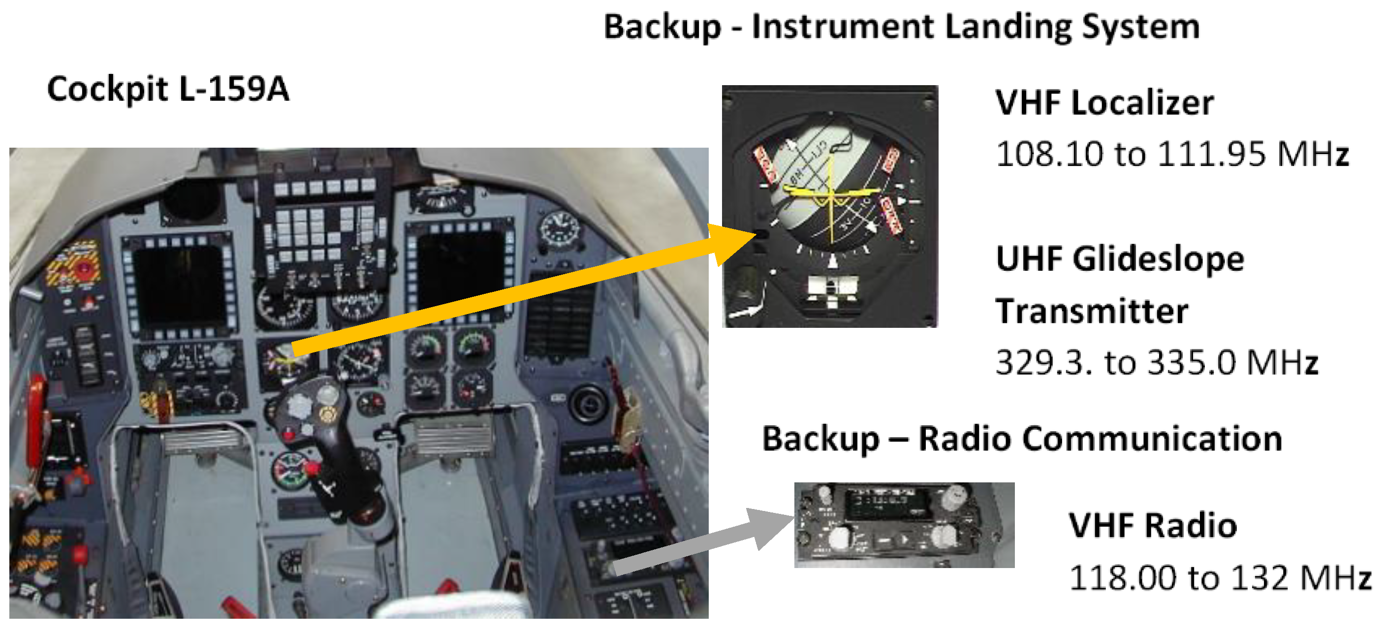
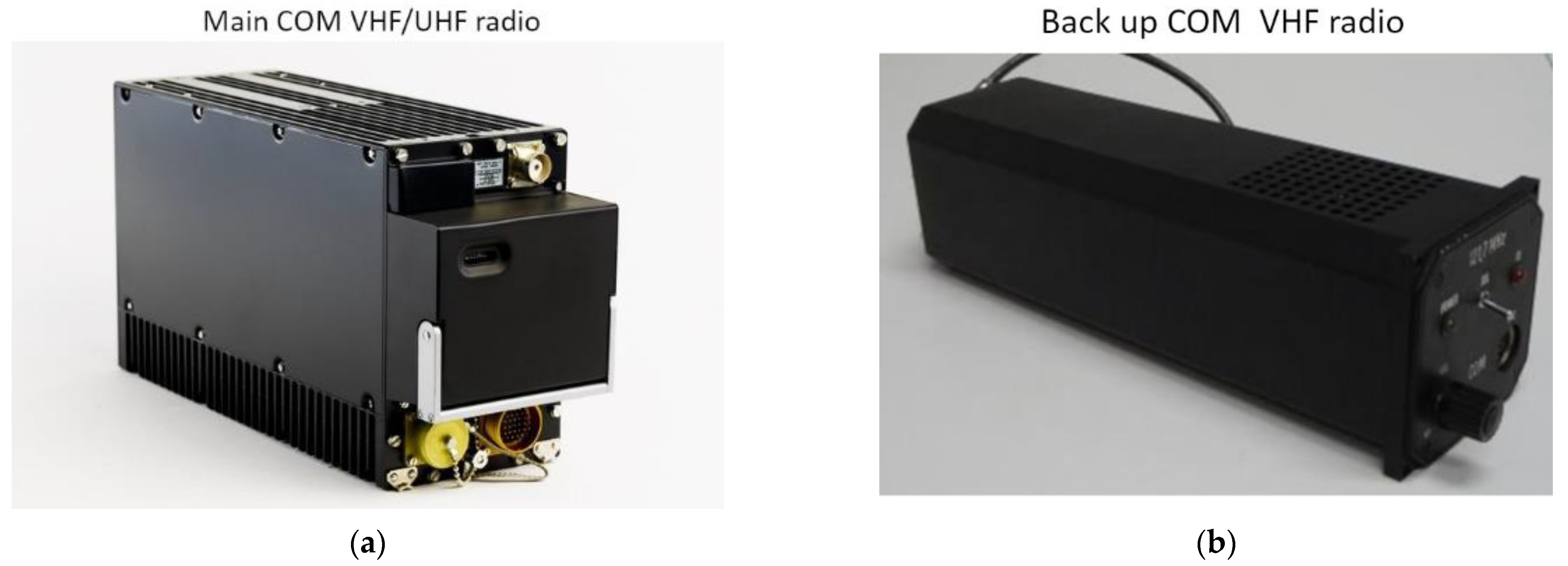
Another example of impacts of power electronics are EMI measurement results challenging the certified airborne radio communication system LUN-3520 (3524), which complies with Radio Technical Commission for Aeronautics (RTCA) and International Civil Aviation Organization (ICAO) standards. LUN is a VHF (118–136.975 MHz) radio communication system using AM modulation and frequency channel separation of 25 kHz. LUN-3520 (3524) complies with the following:
  • RTCA DO-160C—“Environmental Conditions and Test Procedures for Airborne Equipment” (currently in version DO-160G, when after December 2014, parts “Radio Frequency Susceptibility, Radiated and Conducted” and “Emission of Radio Frequency Energy” were removed and placed into the new DO-357);
  • RTCA DO-186A—“Minimum Operational Performance Standards (MOPS) for Airborne Radio Communications Equipment Operating within the Radio Frequency Range 117.975–137.000 MHz” (since 2005 in version DO-186B).
Since the equipment is used in a variety of aircraft, LUN also complies with other standards [4,5,20,21,22,23].
The experimental radio receiver tested in detail is the RTCA/DO-186A class C and E certified and equipped with a squelch function. The declared sensitivity of the receiver is better than 5 µV. The level of suppression of unwanted (spurious and image) responses is at least 60 dB, in accordance with [20,21,22,23,24] and RTCA/DO-180A, part 2.2.8. The detailed synthesis of the VHF radio system immunity and effects of the modern power electronics show the impact of the interferences. The analyses demonstrate significant threats and risks resulting from interferences between VHF radio systems and power electronics switching.
As mentioned above, most airborne VHF/UHF receivers are based on the superheterodyne or double-superheterodyne concept. A simplified block diagram is shown in Figure 13. The superheterodyne receiver uses frequency mixing of a received signal to fix an intermediate frequency IF. The idea is to reduce the incoming frequency to a suitable frequency to be amplified efficiently. The efficiency of operation in view of resistivity versus interfering signals of the superheterodyne receiver (SHR) depends on the frequency mixing, which is shown in Figure 13.
Selection and amplification of the desired signal at the tuned frequency ωD is the first part of the SHR at the RF front-end. The first block is a high-quality band-pass filter (BPF) with appropriate sensitivity and selectivity. The BPF circuit is responsible for the overall receiver’s selectivity and its ability to reject signals in close proximity to the desired frequency band. In most cases, the SHR embeds the RF tunable band-pass filter and RF amplifier. The signal at the output of the RF front-end is preprocessed to be converted in the frequency. The frequency converter is translated from the RF frequency band to the IF band by using the mixer and ωLO signal of the local oscillator—synthesizer. The result is the combined signals, which contain a large variety of signal characteristics such as the series of harmonics, according to the equation
m ω L O ± n ω D
where m, n are integers {0,1,2,3, …} expressing multiples of frequencies; ωD is the frequency of the desired input signal; and ωLO is the frequency of a signal produced by the local oscillator. The output signal ωIF of the mixing process is constant and does not change for any possibly tuned ωD. To achieve the desired effect, the ωLO has to be changed in parallel with ωD to keep a constant difference [1,25].
In view of power electronics effects, the input signal from the antenna is filtered to reject the image frequencies. In the superheterodyne receiver, the oscillator produces a signal for mixing to shift the incoming signal to a specific intermediate frequency ωIF. The ωIF signal is filtered and amplified. The demodulator demodulates the ωIF signal to obtain the original modulation, generally supporting the aircraft LF block.
Despite all the advantages of the heterodyning in a receiver, there are many potentially critical channels—frequencies—which open “back doors” that make the receiver susceptible to interferences produced by power electronics processing. Practically, it is not always an easy task to identify what mechanism is the cause of the one particular interference.
One of the critical frequencies is the image frequency ωIMG. The signal, if present, at the ωIMG can penetrate through the input RF band-pass filter in case of an insufficiently low quality of this filter. Generally, the input RF filter does not have too steep characteristics, and it is solved by the superheterodyne reception itself. Nevertheless, such way of reception cannot effectively confirm all the interfering signals are emitted by the power electronics.
The difference between the desirable signal at ωD and a critical signal at ωIMG is 2x ωIMG.
ω I M G = ω D ± 2 ω I F .
Once the signal at the image frequency ωIMG penetrates into the receiver, it generates an unwanted response at the IF band after the mixer (MIX) which will be amplified by the IF amplifier and cannot be suppressed anymore. The only way to prevent the signal at the image frequency from interfering with the receiver and to increase immunity against the image response is to increase the selectivity (quality) of the RF circuits.
Another hazardous channel into the receiver is through the frequency equal exactly to ωIF. If the signal at the input of the receiver is at the ωIF and penetrates through the RF front-end, then it appears at the input of the MIX. Such an MIX interference is independent of the current frequency tuning of the receiver and the desirable ωD. A hazardous frequency is therefore the difference between ωD and ωLO:
ω I F = ω L O ω D   or   ω I F = ω D + ω L O .
The MIX interference occurs when a strong source generates a signal at ωIF and the input band-pass RF filter is not able to suppress it under the acceptable level. In the EMI case, a hazardous signal penetrates into the IF stage and interferes with the desirable signal at ωD.
In addition, the imperfect local oscillator produces a signal, which is not ideally harmonic. It means the frequency spectrum of such a signal contains not only the basic ωLO but also a series of higher-order harmonics nωLO, where n = {2, 3, 4, …}. The entire series of harmonics from the LO is introduced to the mixer MIX. The MIX then produces a combinatorial signal for every specific harmonic, creating a much more complex scenario with many more various possible combinations, resulting in a critical ωIF frequency [13,14,15]. For instance, the presented example of the second harmonic of the LO, 2ωLO, is
ω IMG 2 2 ω LO = ( 2 f ω LO + ω IF ) 2 f LO .
From Equation (14), if any signal at the frequency (2ωIMG—2ωLO) or (2ωLO—2ωIMG) can successfully enter the receiver, then its output of the MIX is translated as the ωIF and its rejection is not possible any more. As such, the signal then interferes with the desired signal at ωIMD.
As shown above, one of the critical frequencies is the image frequency fIMG [4,5,20,21,22,23], defined as: the mixer uses non-linear components and processes, and the output of the mixer may include the original RF signal at fD, the local oscillator signal fLO, and two new frequencies fD + fLO and fD + fLO. The mixer may also produce additional signals of higher-order inter-modulation products. The undesired signals are removed by the IF band-pass filter to obtain only the IF signal that includes the original modulation. The quality of the IF modulation is important to provide to the receiver to mitigate the effects of the power electronics interfering signals. One major disadvantage is the problem of determining ωIF so the receiver can reject interfering signals at the image frequency [25,26].
Likewise, additional dangerous frequencies—hazardous channels—exist due to the non-linear input/output characteristics of the active circuits (amplifiers and mixer) of the receiver. When the signal is processed by a non-linear circuit, the circuit not only excites the output of the spectrum with the same harmonics content but also generates completely new harmonic members— called non-linear distortion. For a power electronics example, let the input of a non-linear circuit be two signals with angular frequencies ω1 and ω2 as described:
x ( t ) = A 1 cos ω 1 t + A 2 cos ω 2 t ,
where A1 and A2 are the amplitudes of the signal. The output of the circuit is the signal which contains the series of harmonics:
m ω 1 ± n ω 2 ± p ω 3 ± ,
where m,n = {0,1,2, 3, 4, …}. The interferences and disturbances which occur in this case and in one of the most intrusive cases are called inter-modulation. The inter-modulation disturbance appears when two or more strong signals with different frequencies are received simultaneously and both proliferate at the input of the IF amplifier. Practically, there is a desired signal at ωD and other more strong signals. The RTCA DO-186B, part 2.6.2.10 describes the procedure for inter-modulation immunity tests using a two-signal method. A dangerous situation arises when the disturbing signal is at the frequency close to ωD and the radio combines the signal with the frequency inside of the band pass of the IF filter [25,26].
Apparently, due to a non-linear character of the input–output characteristics of the receiver’s circuits, higher-order harmonics combinations between the desired and disturbing signals occur. Some of them, causing the receiver to become susceptible to the inter-modulation type of interference, appear in a frequency band passing through the IF filter and IF amplifier. Hence, two signals at frequencies ω1 and ω2 are received, resulting in ω1, ω2, 2ω1, 2ω2, 3ω1, 3ω2….., and higher frequencies being present at the input of the MIX. At the input of the IF filter, therefore, combinations of 2ω1 ± ω2, 3ω1 ± 2ω2, 2ω2 ± ω1, and others occur. Hence, the critical frequencies are
ω d i s t u r b i n g = ω s 2 ω I F ,
and the interfering signal penetrates as an image signal, since
ω s 2 ω I F ω L O = ω I F
When the interfering signal is at
ω d i s t u r b i n g = ω I F ,
it penetrates directly through the IF filter and amplifier as an IF signal.
Interferences at 2ωs are disturbing when
ω d i s t u r b i n g = 1 2 ω s ,
since
2 1 2 ω s = ω s .
Similarly, disturbances occur when
ω d i s t u r b i n g = 1 k ω s = γ k ,
where k = (1, 2, 3, …).
The inter-modulation disturbance of the third order
2 ω s ω d i s t u r b i n g ,
When the interferences are at its frequency, is close to ωs. The inter-modulation disturbance of the fourth order according to
ω d i s t u r b i n g = ω L O 1 2 ω I F = ω L O 3 2 ω I F ,
interferes since
2 ( ω L O ( ω D 3 2 ω I F >) ) = ω I F

4. Measuring and Testing Workplace

For testing purposes, an instrumentation workplace that enables interference testing of systems with the superheterodyne radio receiver concept was created. For such testing, the main part of the workplace is a jammer system based on a transistor PWM power switch, which allows generation of interference by switching the power to inductive load with a square waveform with an adjustable carrier frequency. The system enables targeted setting of interfering functions of the electronic radio receiver in the bandwidth of 500 Hz to 200 kHz. Figure 14 shows the jammer system according to [12].
The EMI testing system consists of a power switch and a PWM modulator, which provides a power electronic interface between an electric source and an electric load: in our case, the power amplifier and antenna. Such concept allows not only setting the frequency but also simulating the PWM control of the used frequency converters on board the aircraft, using the possibility of duty cycle changing and modulation control, or unmanned aerial vehicle (UAV) drives, which can be a source of interference of ILS ground transmitters which can fundamentally influence aircraft in the approach to landing phase. Furthermore, the interference system is equipped with an amplifier, which allows continuous adjustment of the output power level with a modular antenna connection. The implemented system enables the generation of interference and the simulation of the formed interfering signals, which can be produced on commutators of electric motors or electric DC drives of aircraft. It also allows the simulation of interference by power electronics circuits that use PWM modulation to power supply of asynchronous and synchronous generators or servo drives used on board the aircraft.
The interfering signal is propagated both by electromagnetic emission and through the aircraft’s distribution buses. In particular, frequency converters are the source of such interference on board the aircraft. The measuring workplace enables testing where interference directly penetrates into electronic circuits through the air. As mentioned above, generated interference frequencies, especially in the order of 1 kHz, are potentially possible because such frequencies interfere with the signal processing circuits of the superheterodyne receivers. In the article, the cases with frequencies around 800 Hz are presented. These frequencies are potentially dangerous as similar frequencies are used in power systems because the choice of frequency is very closely related to the level of the processed power. The higher the power level processed by the power electronics converter, the lower the frequencies that can be used in the switching circuit, as the switching losses of the converter increase with the frequency. For these reasons, frequencies from 800 Hz to 2.5 kHz are used very often. In addition, these high-level frequencies of processed power operate with voltages of up to hundreds or thousands of volts, which can very easily penetrate into the circuits and produce interference of feedback control signals or interference of data signals on board the aircraft. Furthermore, these frequencies may produce interference on radio communications.
On board the aircraft, interference can be propagated by galvanic, capacitive, inductive, or electromagnetic emission in direct or secondary coupling. In this case, only the transmission by electromagnetic wave emission of a distant electromagnetic field is the subject of the test. Transmission by electrical or magnetic coupling in the near field between the receiver object and the frequency converter, for example, is less probable. In particular, in case of radiation transmission, the intensities of the electric Ei or the magnetic field Hi are used. These intensities of the interfering fields Ei and Hi are converted by measuring antennas to the voltage Vi at the terminals of the system, producing simulated interference. There are obvious coefficients of antenna factors of used antennas for a given measuring frequency of interference or bandwidth of interference. The basic device for evaluation is a spectrum analyzer, operating in the frequency range of 10 Hz to 9 GHz. The interfering signals that have been radiated into the area of the superheterodyne receiver are at frequencies from 500 Hz up to 1000 MHz. For testing, the loop antenna in the range up to 30 MHz with a H-component and the rod antenna with an E-component were used. In the bandwidth up to 200 kHz, interference phenomena caused by the H-magnetic component of the electromagnetic field predominates. Loop antennas with amplifiers for a given frequency band are typically used for measurement. For higher frequencies, both the Hi-component and the Ei-component were tested. Interfering signals in the operating area of electronic circuits were realized by special electric and magnetic field probes. The use of the probes is shown in Figure 15.
The test design (Figure 14 and Figure 15) allows monitoring the undesirable phenomena of individual interfering components simulating power electronics circuits on individual blocks of the superheterodyne receiver and, consequently, determining the limits of electromagnetic immunity and weaknesses of the receiver from the EMC point of view of tested devices on board the aircraft. In addition, the designed system allows obtaining the relative information about the intensity of interference in a given operation area or in a given circuit. Consequently, it affords identifying the places of radiation or places of penetration of interference into the electronic circuits of the receiver.
It should be emphasized that the effects of emitted measuring interference signals cause a measurement uncertainty. Although the overall inaccuracy of the whole measuring chain, i.e., interference source, amplifier, and antenna, is quite high, for testing purposes, the system is able to analyze receiver capabilities against unwanted reception channels. An example of the use of our interference testing systems is shown in Figure 16, where an 800 Hz interference signal is generated. The voltage from the PWM modulator is led to the control of the switching transistor.
The measurement system, described above, was also extended with the possibility of testing for EMI with narrowband or wideband signals. The switching slew rate significantly affects the generated interference for the radio receiver testing with narrowband or wideband signals [24,25]. The signals’ slew rate is set on the transistor by the change in the VGS (voltage from gate to source) of the gate voltage with a constant emitter–collector voltage. The dynamics of the switching edge is influenced by the series of capacitances of the transistor and the gate resistor Rg. These capacitances appear in the transition of the P-channel capacitance and gate in the N-MOSFET (N channel metal–oxide–semiconductor field-effect transistor) switch. The width of the channel varies depending on the width of the spatial charge between the P layer and the epitaxial layer of the MOSFET and thus its total charge [27]. This charge describes the equation
C = d Q d V ,
where dQ is the derivative of charge from the power source.
Examples of the generated interference when changing the steepness of the rising edge are shown in Figure 17. An example of a higher level of interference is the case of Figure 17a, where the steeper edge produces higher peaks of voltage up to 700% and thus gets into the systems more easily, in contrast to the case in Figure 17b, where a slower slew rate of the rising edge is visible and thus a smaller post-transition overshoot and consequently less interference, which is produced by the test system.
The main benefits of the design of the EMI test source are described below. Narrowband interference can be suppressed with special tuned filters. However, as can be seen from the measurements, the interference of the power electronics circuits is rather wideband interference, i.e., such that the spectral width is greater than the bandwidth of the intermediate part of the superheterodyne receiver. These interfering signals are mainly produced with one-time or periodic pulses, which the designed system allows generating. The advantages of the concept can be seen especially in the area of measures recommended for airborne radio systems to avoid interferences. The problem of interference suppression in onboard aircraft systems is usually very problematic and presents a complicated solution. Such solutions aim to increase the immunity of the airborne superheterodyne receivers so that receivers are able to resist the interference in an electrically problematic environment. However, the backup receivers used on board the aircraft generally represent a simplified solution, which also represents a reduced ability to suppress external interference. The design and topology of the interference filters are determined by the size of the processed power and frequencies. In this case, it is obvious that the circuit concept based on mass relevant materials should be used for low-frequency interference suppression, which in aeronautics represents an additional load and increase in the weight of the filter and consequently the whole electronic device.
The design issues of filter circuits that play an important role in reaching the goal of parameter optimization such as the weight and size can even lead to a reduction in the overall device resistance to EMI. These principles, as has already been mentioned, are mainly used in backup systems so that the backup system should not represent a weight load on board the aircraft. In addition, there is a problem where the use of interference filters can degrade the operating conditions of the used device, e.g., the receiver’s sensitivity. Interference is also related to the shielding thickness and shielding efficiency. The total shielding efficiency with the shielding thickness of 1 mm for frequencies up to 1000 Hz is around 60–80%. The 3 mm shielding efficiency is up to 90% [15,16,28]. It is evident from the examples that the methods of interference suppression by power electronics circuits are also significant from the design point of view, as the measures significantly increase the weight of the systems on board the aircraft [20,23].
The testing method (Figure 14) not only enables the measurement of interfering signals and the behavior of the radio system in the environment of the EMI but it also enables the solution of issues in the design of onboard equipment when choosing optimization processes between mass relevant filters and EMI shielding. Since it is not possible to achieve ideal EMC of superheterodyne receivers for the mentioned reasons, it is necessary to perform measurements and testing for verification of the correct functions of onboard devices.

5. Experimental Verifications

On board an aircraft, electrical power-to-energy results from power converters with PWM switching, where SiC IGBTs (silicon carbide, insulated-gate bipolar transistors) are mainly used, which can produce disturbing signals and consequently reduce the quality of the radio reception. The problems of such interfering signals are analyzed in this section using the superheterodyne receiver concepts [12,26,27,28,29].
High-speed switching of power devices produces an EMI, which is potentially dangerous for aircraft radio jamming. Possible electronics interference that may arise at the aircraft electronics include power switching, where a short rise and fall of power contains significant harmonic energy levels. The interference power does not focus just on a certain part of the frequency spectrum but occurs in a wide band of frequencies from kHz to up to tens of MHz (see Figure 3b), where wideband interfering signals are produced by power electronics processing. It is evident from Figure 3b that higher speeds of switching produce higher peaks of voltage, producing serious EMI stresses, noise, and electromagnetic interferences. The HF switching in the PWM converter may produce harmonics and inter-harmonics in the range of wide-spread Hz and can have a serious impact on the VHF/UHF radio systems. Such an effect may influence the basic integrity and normal operation of the airborne equipment [28,30].
An example of EMI is discussed below and the results of experimental verification of the backup radio system are shown in Figure 18. The interfering signals that produce the interferences of VHF radios are marked by red colors. Experimental verifications of the backup radio certificated in accordance with RTCA/DO-186A class C and E are presented here. The sensitivity of the receiver is declared better than 5 µV. The level of suppression of unwanted (spurious and image) responses, in accordance with RTCA/DO-180A, part 2.2.8, is at least 60 dB. From the receiver EMI signal analyses above, we analyzed the signals that can be potentially dangerous and can cause the intrusion into the receiver circuits. The frequencies that are sensitive to the potential hazard of the VHF receiver based on the superheterodyne or double-superheterodyne concept in the undesired response can be categorized into several groups, as can be seen in Table 1. The frequency fs is selected—the desired frequency of the input signal—and fIF is an intermediate frequency of the receiver. The results of the experimental verification of the influence of aircraft power electronics versus radio compatibility are shown in Figure 18. In the following experimental results, we will focus on the intrusion of the interference signal into the reception circuits and into the receiving channel according to Equation (22) (i.e., through f = 59 MHz), as shown in Figure 18, which aims to summarize measurements on radio stations on selected channels according to Table 1.
The results of our experimental verifications in Figure 18 show the serious situation where aircraft power electronics affects airborne radio systems. The selectivity of the radio receiver is a crucial parameter when considering the immunity of the receiver [5,6,7,22,23,24]. The ability of the receiver to suppress or reject unwanted and disturbing signals determines the amount of possible frequencies at which those disturbances can influence the receiver and trigger the response. Practical results indicate that not only strong but also weak disturbing signals can interfere within the receiver. Disturbances generated by power electronic circuits are mostly significantly stronger comparing to weak signals received by the antenna. The experiment design presented in Figure 14 was prepared to use the switching frequency over an interval of 800 Hz–20 kHz, which is currently normally used [7,8,
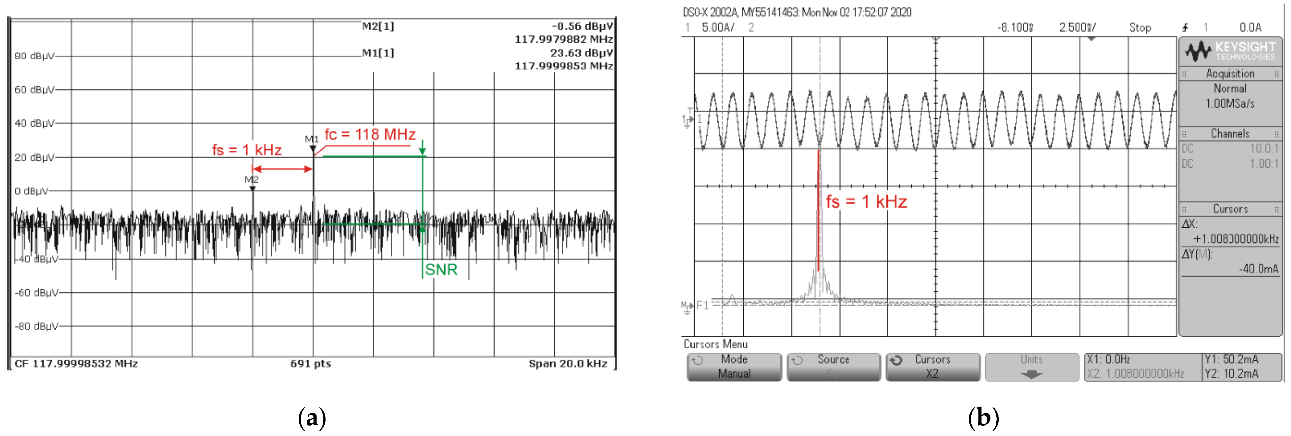
29]. The presented experimental results are for fs = 118 MHz. The power electronics uses 822 Hz (see Figure 7b), and 2 kHz of power switching. As can be seen in Figure 18, power electronics affects, for example, case B2, at the frequency of 59 MHz. Very likely, some of the higher-order harmonics products from the 2 kHz power electronic switching belong to the specific critical channel B2, and it can potentially reduce the immunity of the radio receiver. The problem is when the interfering signal physically intrudes into the radio station and consequently causes such interferences.
The results of the previous analyses versus the radio RF receiver LUN were experimentally verified together with the power electronics system of the servomotors. Power electronics switches (probably based on the MOSFET technology) operate in high frequency and provide receiver disturbances. The consequence of the disturbance emitted by the power electronics was serious in terms of the reliability of the receiver communication system. Switching power electronics of the servo system caused an emitted electromagnetic disturbance that covers the large-frequency range, as can be seen in Figure 19. The frequencies ranging from 10 kHz to 10 MHz are extremely ranged spectral contents that are affected by switching harmonics of the switch mode power supply of the servo system. As mentioned above, the problem at high frequencies is the transient in the switching of power devices. We described the system to change the edge of the switching process in our approach because the edge steepness is a very important parameter in analyses of an EMI of power electronics. Switching in the transient of devices used in the servo system produced high-frequency resonances from 10 MHz to 30 MHz. In addition, the interfering signals of the control stage produced an EMI as well. The results of this experimental verification of the servo system show that power electronics produces very complex interfering signals to provide jamming effects of the backup radio system LUN. Detailed and complex analyses of how the EMI signals transmit into the receiver are shown below and in Figure 20.

6. Discussions

Besides others, the LUN-3520 (LUN-3524) radio communication system contains an AM receiver (specifically A3E with DSB) for the frequency band of 118–137 MHz. However, the receiver is professionally built and certified, which may allow interfering signals generated by power electronics to penetrate and can decrease the basic quality of normal reception in backup radio systems. As mentioned in the Introduction, a backup VHF (UHF) communication or navigation receiver and its instrument parts are typically built as simple or double-heterodyne receivers in low-dimension blocks with a low mass [5,11,29]. The design does not allow using a high level of mechanical shielding and consequently allows the intrusion of specific disturbing signals. Figure 20 shows the effect of switching with detailed analysis of the situation inside the radio circuits. Figure 20 also shows the effect of how the interference signal intrudes the reception channel, according to Equation (22), when the interference penetrates the radio at the frequency of 59 MHz. The interfering signal is 118 MHz, the intermediate frequency is in red (22.114 MHz), the distortion is in black (1 kHz), green is the interfering signal (frequency 822 Hz) produced by the power electronics, and brown is the switching frequency (2 kHz) of the power electronics.
To understand how the interference signal reaches the output of the radio station, it is necessary to describe the effect of the IF filter. The IF filter is the custom-designed unbalanced discrete crystal filter (DCF) with Chebyshev approximation [24,25,31]. The IF filter is designed to provide the required selectivity in accordance with current standards for VHF airborne radios. The IF frequency is 22.114 MHz which gives us the opportunity to use the fixed RF filter for the entire frequency band (118–137.000 MHz) with appropriate image frequency rejection. Measured results are presented in Figure 20c,d.

7. Conclusions

During standard as well as non-standard air traffic situations, many air traffic management (ATM) services are provided using standardized VHF/UHF radio channels. The same channel bandwidth is used for emergency services and, consequently, it is far more critical when emergency services are unavailable. A potential failure of VHF/UHF radio channels is due to disturbances by the electromagnetic interferences (EMI) emitted by the thousands of electronic circuits and power processing on board an aircraft and around radio systems. In aeronautical systems, the EMIs can be very dangerous for electromagnetic compatibility processes and can potentially reduce the safety level in the air transportation.
On board the aircraft, there are many systems based on traditional technologies, especially in backup systems that belong, as their main counterpart, to the group of critical airborne systems. One of the backup instruments is the radio system, which is used for aeronautical communication—ATM services—as well as for navigation, where the most critical are VHF/UHF systems for approaching and landing. Although typical communication and navigation systems are normally based on SDR technologies, there are backup equipment that must operate in non-standard conditions and therefore they are based on simple analog technologies such as superheterodyne or double-superheterodyne VHF/UHF radios, ILS receivers, and/or analog indicators. Beside the use of traditional technologies, newer power electronics can cause unique types of disruptions, especially the use of SiC or GaN switches, from which their switching action can cause wideband interferences, including interferences in VHF and UHF bandwidths used for provision of communication and navigation services in aviation.
The presented results show that the designed airborne receivers, based on traditional technologies, are not resistant to such new types of interferences from emerging power switching devices and there are many ways to get the disturbing signal into the receivers’ circuits that have inadequate shielding. Such interferences have various levels of danger; as the sensitivity decreases, the marker receiver indicates incorrect navigation positions. Such problems must be taken into consideration not only during the design of new aircraft systems but also through modernization and additional avionics installation, where such types of technologies can cooperate.

Author Contributions

Conceptualization, J.L., R.B. and J.B.(Josef Bajer); methodology, J.L., R.B., J.B.(Josef Bajer); validation, E.B., J.B.(Jan Boril); formal analysis, J.L. and R.B.; investigation, J.L., E.B. and R.B.; writing—original draft preparation, J.L., R.B. and E.B.; writing—review and editing, J.L., R.B. and E.B; visualization, J.B.(Josef Bajer); supervision, J.L.; project administration, J.B.(Josef Bajer); All authors have read and agreed to the published version of the manuscript.

Funding

This research received no external funding.

Acknowledgments

The work presented in this paper has been supported by the Czech Republic Ministry of Defence—University of Defence development program “AIROPS”.

Conflicts of Interest

The authors declare no conflict of interest.

References

  1. Leuchter, J.; Steklý, V.; Blasch, E. Investigation of Avionics Power Switch Loading Versus Aircraft Electromagnetic Compatibility. IEEE Aerosp. Electron. Syst. Mag. 2015, 30, 24–34. [Google Scholar] [CrossRef]
  2. Tooley, M.; Wyatt, D. Aircraft Electrical and Electronic Systems: Principles, Maintenance and Operation; Routledge: England, UK, 2009. [Google Scholar]
  3. RTCA. DO-160C Environmental Conditions and Test Procedures for Airborne Equipment. Available online: https://do160.org/rtca-do-160g/ (accessed on 26 October 2020).
  4. EU Regulation No 1079/2012 of 16 November 2012 Laying down Requirements for voice Channels Spacing. Available online: https://eur-lex.europa.eu/LexUriServ/LexUriServ.do?uri=OJ:L:2012:320:0014:0024:EN:PDF (accessed on 26 October 2020).
  5. ICAO. Annex 10—Aeronautical Telecommunications—Volume III—Communication Systems, ICAO Standards and Recommended Practices and guidance material, 2nd ed.; ICAO-ECP: Montréal, QC, Canada, 2007. [Google Scholar]
  6. European Organization for Civil Aviation Equipment. EUROCAE ED-137B, EUROCAE Standard Revision B; European Organization for Civil Aviation Equipment (Eurocae): Paris, France, 2012. [Google Scholar]
  7. Kimoto, T.; Cooper, A.J. Fundamentals of Silicon Carbide Technology: Growth, Characterization, Devices and Applications, 1st ed.; Wiley-IEEE Press: Hoboken, NJ, USA, 2014; ISBN 978-1118313527. [Google Scholar]
  8. Mohan, N.; Udeland, T.M.; Robbins, W.P. Power Electronics: Converters, Applications, and Design; John Wiley & Sons, Inc.: Hoboken, NJ, USA, 2003; ISBN 0-471-22693-9. [Google Scholar]
  9. Zare, F.; Kumar, D.; Lungeanu, M.; Andreas, A. Electromagnetic interference issues of power, electronics systems with wide band gap, semiconductor devices. In Proceedings of the 2015 IEEE Energy Conversion Congress and Exposition (ECCE), Montreal, QC, Canada, 20–24 September 2015; pp. 5946–5951. [Google Scholar] [CrossRef]
  10. Dzunda, M.; Dzurovcin, P.; Koscak, P.; Semrad, K. Impact of Interference on DME Operations. In Proceedings of the 2019 Modern Safety Technologies in Transportation (MOSATT), Kosice, Slovakia, 28–29 November 2019; pp. 49–52. [Google Scholar] [CrossRef]
  11. Moglie, F.; Micheli, D.; Laurenzi, S.; Marchetti Primiania, V.M. Electromagnetic shielding performance of carbon foams. Carbon 2012, 50, 1972–1980. [Google Scholar] [CrossRef]
  12. ETSI. Electromagnetic Compatibility and Radio Spectrum Matters (ERM). European Standard (Telecommunications Series) ETSI EN 300 676-1. Available online: https://www.etsi.org/deliver/etsi_en/300600_300699/30067601/01.04.01_60/en_30067601v010401p.pdf (accessed on 12 November 2020).
  13. EUROCONTROL. Guidance Material for the Certification and Operation of State Aircraft in European RVSM Airspace; EUROCONTROL Regulation, 2.0 ed.; Related Issue; EUROCONTROL: 2014. Available online: https://www.eurocontrol.int/sites/default/files/2019-07/2014-05-guidance-material-rvsm-v-2.0.pdf (accessed on 12 November 2020).
  14. EUROCONTROL. Eurocontrol Experimental Centre: RVSM and TCAS in European Airspace. Available online: https://www.eurocontrol.int/sites/default/files/library/010_RVSM_and_TCAS_in_European_Airspace.pdf (accessed on 14 January 2021).
  15. Geisc, R.; Neubauer, B.; Zimmer, G. Scaled Measurements of Multipath Propagation and Navigations Systems—A Practical Example for ILS. In Proceedings of the 2019 Joint International Symposium on Electromagnetic Compatibility, Sapporo and Asia-Pacific International Symposium on Electromagnetic Compatibility (EMC Sapporo/APEMC), Sapporo, Japan, 3–7 June 2019; pp. 482–485. [Google Scholar] [CrossRef]
  16. Lin, H.; Sun, X.; Liang, F.; Li, Y. Simulation and Analysis of Active Disturbance of Electrified Railway to Instrument Landing System. In Proceedings of the 2019 IEEE 3rd Advanced Information Management, Communicates, Electronic and Automation Control Conference (IMCEC), Chongqing, China, 11–13 October 2019; pp. 1034–1038. [Google Scholar] [CrossRef]
  17. Oxford Aviation Academy, Oxford ATPL-4th Ed-Book 11-Radio Navigation; Oxford Aviation Academy: Shoreham, UK, 2008.
  18. Boril, J.; Smrz, V.; Blasch, E.; Lone, M. Spatial Disorientation Impact on the Precise Approach in Simulated Flight. Aerosp. Med. Hum. Perform. 2020, 91, 767–775. [Google Scholar] [CrossRef] [PubMed]
  19. Olive, X.; Sun, J.; Lafage, A.; Basora, L. Detecting Events in Aircraft Trajectories: Rule-Based and Data-Driven Approaches. Proceedings 2020, 59, 8. [Google Scholar] [CrossRef]
  20. Department of Defense—USA. MIL-E-5400: Military Specification, Electronic Equipment, Airborne, General Specification; Department of Defense—USA: Washington, DC, USA, 1986.
  21. MIL-STD-461F. Requirements for The Control of Electromagnetic Interference Characteristics of Subsystems and Equipment; Department of Defense—USA: Washington, DC, USA, 2007. [Google Scholar]
  22. RTCA. DO-186A Minimum Operational Performance Standards for Airborne Radio Communications Equipment Operating within the Radio Frequency Range 117.975–137.000 MHz; RTCA: Washington, DC, USA, 1995. [Google Scholar]
  23. Department of Defense—USA. MIL-STD-188-243: Tactical Single Channel Ultra High Frequency (UHF) Radio Communications; Department of Defense—USA: Washington, DC, USA, 1989.
  24. IEC/TR EN 61000-2-1. Electromagnetic compatibility (EMC)—Part 2: Environment—Section 1: Description of the Environment—Electromagnetic Environment for Low-Frequency Conducted Disturbances and Signaling in Public Power Supply Systems. Available online: https://webstore.iec.ch/publication/4127 (accessed on 2 February 2021).
  25. Leuchter, J.; Bajer, J.; Bojda, P.; Blasch, E. Immunity Testing in an Airborne Radio-Communication System. In Proceedings of the 34th Digital Avionics Systems Conference (DASC 2015), Orlando, FL, USA, 13–17 September 2015; ISBN 978-1-4799-8939-3. [Google Scholar]
  26. Williams, T. EMC for Product Designers, 4th ed.; Burlington: Newnes, Australia, 2007; ISBN 0750681705. [Google Scholar]
  27. Lucas, K.E.; Pagano, D.J.; Vaca-Benavides, D.A.; García-Arcos, R.; Rocha, E.M.; Medeiros, R.L.; Ríos, S.J. Robust Control of Interconnected Power Electronic Converters to Enhance Performance in DC Distribution Systems: A Case of Study. IEEE Trans. Power Electron. 2021, 36, 4851–4863. [Google Scholar] [CrossRef]
  28. Moir, I.; Seabridge, A. Aircraft Systems: Mechanical, Electrical, and Avionics Subsystems Integration; John Wiley & Sons: Somerset, NJ, USA, 2008. [Google Scholar]
  29. Sim, B.; Jeong, S.; Kim, Y.; Park, S.; Lee, S.; Hong, S.; Song, J.; Kim, H.; Kang, H.; Park, H.; et al. A Near Field Analytical Model for EMI Reduction and Efficiency Enhancement Using an nth Harmonic Frequency Shielding Coil in a Loosely Coupled Automotive WPT System. IEEE Trans. Electromagn. Compat. 2020, 1–12. [Google Scholar] [CrossRef]
  30. Dong, Q.H.; Leuchter, J. Design of Test-system for EMC Investigations of Aviation Electronic Devices. In Proceedings of the 35th DASC Digital Avionics Systems Conference, DASC 2016, Sacramento, CA, USA, 25–29 September 2016; pp. 1–8, ISBN 978-1-5090-5600-2. [Google Scholar]
  31. Shenoi, B.A. Introduction to Digital Signal Processing and Filter Design; John Wiley & Sons: Somerset, NJ, USA, 2005; ISBN 0471656380. [Google Scholar]
Figure 1. Very high frequency (VHF) radio systems in the cockpit of an L-159 aircraft.
Electronics 10 00777 g001
Figure 2. Power processing of onboard aircraft electronics.
Electronics 10 00777 g002
Figure 3. Power electronics electromagnetic interference (EMI): (a) conductive; (b) radiative.
Electronics 10 00777 g003
Figure 4. Shielding of radio frequency (RF) blocks in LUN-3520 (a) and LUN-3524 (b) radios.
Electronics 10 00777 g004
Figure 5. Characteristics of burst signal produced by power electronics.
Electronics 10 00777 g005
Figure 6. Test signal in the VHF bandwidth for aeronautical mobile services, (a) signal in the RF spectrum and the low-frequency (LF) output signal (b), in time domain and its spectrum.
Electronics 10 00777 g006
Figure 7. VHF receiver circuits in the disturbing environment, signal in the RF spectrum (a) and LF output signal, in time domain and its spectrum (b).
Electronics 10 00777 g007
Figure 8. Details of simulated switching processing of SiC power component used in aircraft power electronics.
Electronics 10 00777 g008
Figure 9. Instrument landing system (ILS) receiver block diagram.
Electronics 10 00777 g009
Figure 10. Normal ILS/glide path (GP) indication.
Electronics 10 00777 g010
Figure 11. Disturbed marker (MKR) and GP channel of ILS receiver, (a) only inner marker interference, (b) disrupted GP receiver.
Electronics 10 00777 g011
Figure 12. Indication error caused by ILS/GP disturbance.
Electronics 10 00777 g012
Figure 13. Superheterodyne receiver—simplified block diagram [5,14,20].
Electronics 10 00777 g013
Figure 14. Testing source of electromagnetic interference.
Electronics 10 00777 g014
Figure 15. Realization of special electric and magnetic field probes.
Electronics 10 00777 g015
Figure 16. Generated interference signals.
Electronics 10 00777 g016
Figure 17. Rising edge as the source of electromagnetic interference. (a) High level of interference caused by fast switching; (b) interference with normal switching.
Electronics 10 00777 g017
Figure 18. Measurements of susceptibility of the RF receiver LUN related to undesired signals of power electronics.
Electronics 10 00777 g018
Figure 19. Measurements of power electronics effects as a function of the frequency range of power electronics.
Electronics 10 00777 g019
Figure 20. Resulting frequency spectrum for case of ½ fs, (a) single amplitude modulation (AM) signal, (b) AM signal when DC-DC power converter is active, (c) single AM signal image frequency rejection, (d) DC-DC converter image frequency rejection.
Electronics 10 00777 g020
Table 1. Intermediate frequency of the receiver.
Group A: A:fif
Group B: B1:fs – 2 fif; B2:fs – 3/2 fif
Group C: C2:1/2 fs; C3:1/3 fs; C4:1/4 fs; C5:1/5 fs; C6:1/6 fs
Group D: D:fs – ½ fif
Group E: E1:3/2fs – ½ fif, E2:fs – ½ fif
Publisher’s Note: MDPI stays neutral with regard to jurisdictional claims in published maps and institutional affiliations.

