Article

Parallel Computation of CRC-Code on an FPGA Platform for High Data Throughput

1
Electrical Engineering and Computer Science Department, The Catholic University of America, Washington, DC 20064, USA
2
NASA Goddard Space Flight Center, Greenbelt, MD 20771, USA
*
Author to whom correspondence should be addressed.
Electronics 2021, 10(7), 866; https://doi.org/10.3390/electronics10070866
Submission received: 1 March 2021 / Revised: 3 April 2021 / Accepted: 5 April 2021 / Published: 6 April 2021
(This article belongs to the Section Networks)

Abstract

:
With the rapid advancement of radiation hard imaging technology, space-based remote sensing instruments are becoming not only more sophisticated but are also generating substantially more amounts of data for rapid processing. For applications that rely on data transmitted from a planetary probe to a relay spacecraft to Earth, alteration or discontinuity in data over a long transmission distance is likely to happen. Cyclic Redundancy Check (CRC) is one of the most well-known package error check techniques in sensor networks for critical applications. However, serial CRC computation could be a bottleneck of the throughput in such systems. In this work, we design, implement, and validate an efficient hybrid look-up-table and matrix transformation algorithm for high throughput parallel computational unit to speed-up the process of CRC computation using both CPU and Field Programmable Gate Array (FPGA) with comparison of both methods.

1. Introduction

NASA Goddard Space Flight Center is currently working on several space based thermal radiometer concepts (e.g., [1,2]). One of these concepts is the Ice-Giants Net-flux Radiometer (IG-NFR) being developed for a future Uranus or Neptune probe mission [3]. IG-NFR is capable of measuring energy fluxes in seven spectral bands from 0.2 µm to 300 µm, each with a 10° field-of-view (FOV) projected into the sky. As the probe descends through the planetary atmosphere, a motor drives the IG-NFR field-of-view sequentially and repetitively in clockwise and anti-clockwise directions to five distinct viewing angles. Figure 1 shows a mechanical drawing and a system block diagram of the IG-NFR instrument. The scientific integrity of IG-NFR relies on all seven spectral channels being data logged simultaneously (in parallel). Along with scientific data, there are also auxiliary data and thermal data to aid with understanding of the scientific data [2]. Here, we will use the IG-NFR as an example space-based instrument to demonstrate error check high data throughput using parallel computation of the CRC-code. Table 1 shows details of both science data and auxiliary data generated by the instrument. As the probe descends rapidly into the atmosphere, remote sensing measurements and error checking computations must be executed in a real-time manner before the spacecraft loses communication connection with the probe, e.g., for a Uranus probe, instruments are being designed for a 10–20 bar atmospheric pressure survival. The processor card proposed in this work is a hybrid platform that contains both an FPGA and an embedded processor. It is the heart of the instrument which controls the IG-NFR, acquires data, packages data, and then forwards it to the probe communication protocol to the spacecraft. The system block diagram is shown in Figure 2. In this paper, we will focus on how to implement the CRC error check protocol on an FPGA to meet the real-time requirements dictated by the constraints of the physical system.

2. CRC Background

A CRC-32 checksum algorithm is often used in data transmission and data storage systems to detect any alteration or corruption of the data [4]. Many digital sensor devices or wireless networks employ this technique in the form of a packet error check [5,6,7,8,9,10,11]. The packet error checking (PEC) is augmented with original data to check if there have been any modifications in the data packet. Both hardware and software CRC generation in serial format are currently well understood. However, with the significant increase of the amount of data being produced by sensor systems, serial CRC generation methods could create a throughput bottleneck that prevent such systems from achieving high performance results [12].
The first version of CRC based computational algorithm was proposed by Peterson and Brown [9]. This algorithm only processes one-bit at a time by utilizing a simple shift register. For an n-bit message, the algorithm’s time complexity is O(n), which significantly affects the throughput of a system. Since then, several techniques have been proposed with the focus on increasing the efficiency of the algorithm that are both software and hardware friendly for implementation.
To obtain high throughput, Sarwate et al. [13] proposed to use a table-based CRC algorithm which can process one byte at a time. This resulted in an 8x speedup than the original serial method by reducing the number of iterative steps it needed to compute the CRC code. The algorithm can be generalized to process multiple bytes at a time, but it always comes down to one thing: trade-off between memory and time complexity. For practical purposes, the table must be small enough to fit into a cache memory for quick access; otherwise, the algorithm will be slowed down significantly due to memory assessment penalty. For example, Sarwate’s table-based algorithm to process 32 bits at a time will require a 232 = 4G entries that is multiple times larger than the cache memory of the commercial system. To deal with this problem, Kounavis and Berry [14] proposed methods called Slicing-by-4 and Slicing-by-8 that use multiple small lookup tables to avoid a memory explosion problem. Moreover, it can be done in parallel via pipelined or concurrency processing.
It is interesting to note that a CRC shift register can also be viewed as a linear system. From a linear system perspective, state-transformation can be computed using matrix multiplication. For example, a CRC code of a message M can be transformed to CRC code of message M appended by multiple zeros through the multiplication with a pre-computed matrix. Derby et al. [15] proposed a parallelization method by taking advantage of this property of the CRC computation circuit.
Most of the previous research [4,5,6,7,8,9,10] can be classified into two main categories: (1) lookup table (LUT) based and (2) matrix transformation (MT) based methods. Recently, parallel platforms such as FPGAs or multi-core CPUs have shown promising results in on-board processing capabilities. The traditional serial CRC generation method does not fully take advantage of the resources from such systems. Several researchers have implemented parallel CRC generation methods as both software algorithms and hardware circuitry [16,17]. In this paper, we propose a hybrid algorithm called hybrid LUT-MT that takes benefits of both methods to speed-up the process while maintaining the memory requirements to a minimum. Chi et al. [18] have a similar concept, but they focused mainly on a software implementation on a multi-core CPU system. In addition, their algorithm will not achieve the theoretical speed-up factor due to thread synchronization management overhead. In this paper, we will describe in detail how to develop the building blocks of the algorithm for an FPGA platform. The system is flexible, scalable, and adaptable which makes it easy to be integrated into a high-performance FPGA-based sensor system. Finally, we will show and analyze results of resource allocation vs. throughput for different configurations.

3. CRC Computational Process

To fully understand the proposed algorithm, we will briefly revisit the serial CRC generation process, lookup table based method, matrix transformation method, and introduce the proposed hybrid LUT-MT algorithm.

3.1. Serial CRC Generation Process

The CRC generation process is basically a modulo-2 arithmetic of two binary polynomials. For a given message M and a generator polynomial G, both can be expressed in polynomial form as [18]:
  M ( x )   =     0 m 1 l i x i ,
G ( x )   =     0 g 1 g i x i ,  
where m and g are the highest degree of the corresponding polynomial, while gi and li are binary coefficients that can be either 1 or 0 at bit position xi. For example, a 32-bit polynomial for CRC-32 can be expressed by both binary formats as 2′b10000010011000001000111011011011 or G(x) = x32 + x26 + x23 + x22 + x16 + x12 + x11 + x10 + x8 + x7 + x5 + x4 + x2 + x1 + x0. The CRC value of the message M can be obtained by the following equation [16]:
  C R C [ M ( x ) ]   =   M ( x ) · x g   m o d   G ( x ) ,
The hardware implementation and the corresponding software algorithm are shown in Figure 3 and Algorithm 1, respectively.
Algorithm 1. Bitwise CRC.
1: Input: Byte Array Data
2: Crc = 0XFFFFFFFF
3: While index < size of data do
4:      CRC = CRC XOR data[index]
5:      for j = 0; j < 8; j++ do
6:         CRC = (CRC >> 1) XOR -(CRC AND 1) AND G(x)
7:      end for
8:      index + 1
9: end while
10: Return CRC XOR 0XFFFFFFFF
After computing the CRC, it is appended to the original message for later use. Since the method only processes one bit at a time, it is labeled as a bitwise CRC algorithm. The time complexity of the algorithm is proportional to the size of the message data stream that renders it unpractical to use for big chunks of data.

3.2. The Sarwate’s Algorithm and Slicing by an N Algorithm

To speed up the process, instead of processing one bit at a time, Sarwate et al. [12] proposed an algorithm that can process eight bits (one byte) at a time. In this algorithm, a lookup table with a 256-entry is precomputed and stored in memory. As mentioned previously, a lookup table must fit into the cache memory to make the process practical. The index of the lookup table is computed by XORing eight bits of current CRC code of that iteration and the current data byte. The new CRC is obtained by shifting current CRC by eight bits to the right then XORing it with the output of the lookup table. Then, it moves to the next byte and continues until the end of all the data bytes of the input message. Pseudocode of Sarwate’s algorithm is shown in Algorithm 2.
Algorithm 2. Sarwate Algorithm.
1: Input: Byte Array Data
2: Crc = 0XFFFFFFFF
3: While index < size of data do
4:   CRC = (CRC >> 8) XOR TABLE[(CRC AND 0xFF) XOR data[index]]
5:   index + 1
6: end while
7: Return CRC XOR 0XFFFFFFFF
Using one single lookup table does not grant much benefit anymore. In order to keep memory requirements reasonably small, a “Slicing-by-N” algorithm uses a multiple 256 entries lookup table which can be derived from the lookup table proposed in Sarwate’s algorithm. More details about the method can be found in Ref. [13]. By performing multiple lookups at once, a modern CPU can speed-up the process by fine-grained parallel processing. As reported in Ref. [14], the speed-up factor can be varied from 2x to 3x depending on the number of tables. Algorithm 3 shows Slicing-by-4 pseudocode, but it can be extended to a general case that uses N tables.
Algorithm 3. Slicing by 4 Algorithm.
1: Input: Byte Array Data
2: Crc = 0XFFFFFFFF
3: While index < size of data do
4:      CRC = CRC XOR data[index:index+3]
5:           XOR TABLE1[(CRC AND 0xFF)]
6:           XOR TABLE2[((CRC >> 8) AND 0xFF)]
7:           XOR TABLE3[((CRC >> 16) AND 0xFF)]
8:           XOR TABLE4[((CRC >> 24) AND 0xFF)]
9:      index + 4
10: end while
11: Return CRC XOR 0XFFFFFFFF

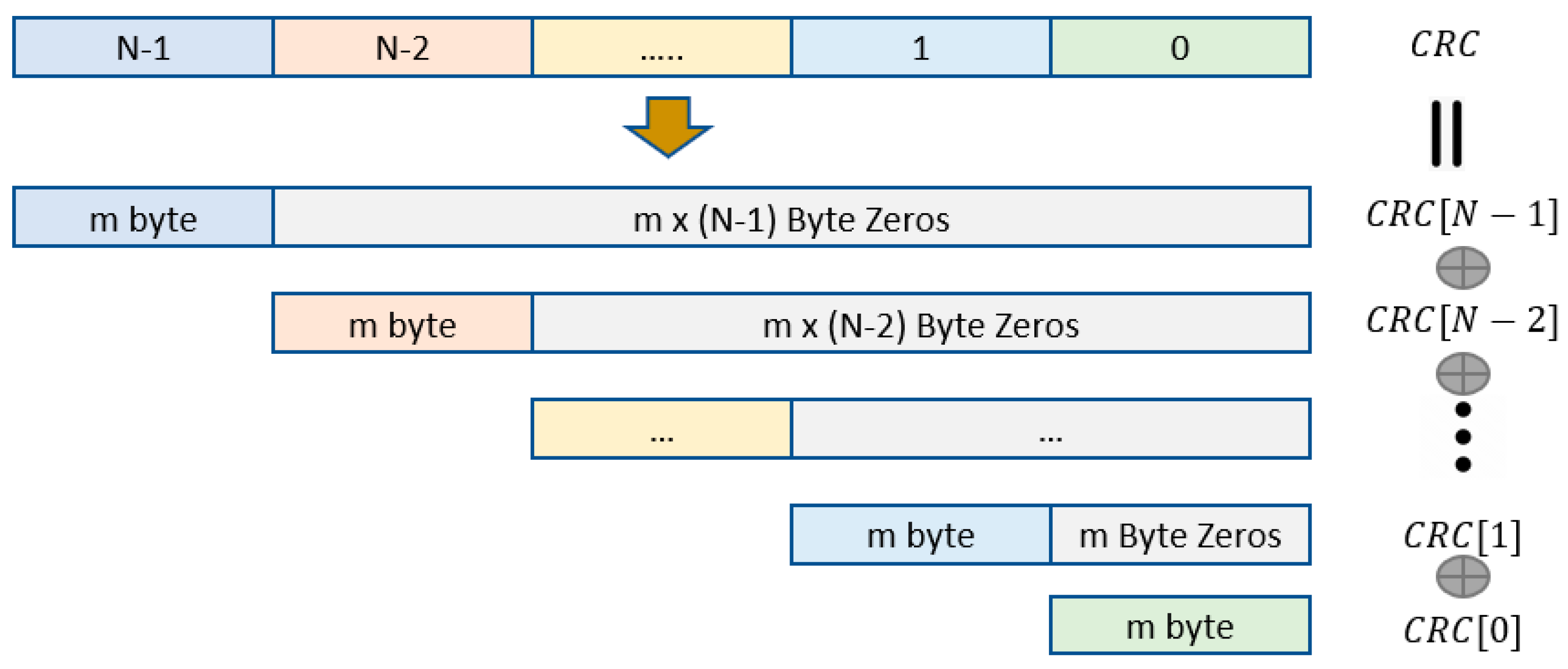
3.3. Matrix Transformation
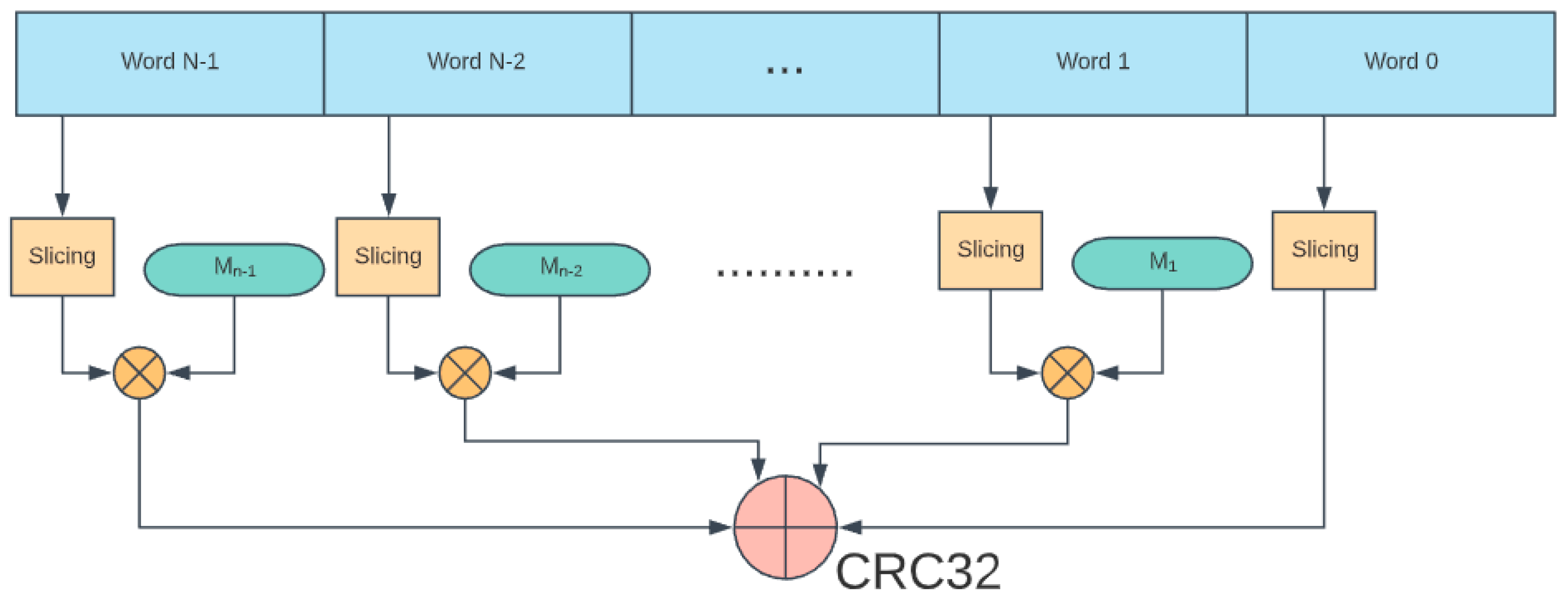
As mentioned before, the CRC linear shift register can be viewed as a linear system. Based on a superposition property, we can decompose the original input message M into multiple small blocks with m-bytes and compute their corresponding CRCs. The final CRC of the whole message is obtained by XORing all the partial CRCs. This method allows us to increase the throughput of the system by parallel computation of the partial CRC of each individual block as shown in Figure 4. One can pre-compute one lookup table for one block. However, it is unpractical to generate lookup tables for a very long input message. The matrix transformation method can be used where it requires only one look-up table for the first block. The CRC code of other blocks can be obtained by multiplying their CRC codes with their corresponding matrices based on Galois Filed Multiplication [14]. The linear shift register in Figure 3 can be described by the state vector state equation:
x ( n + 1 )   =   A x ( n ) + b u ( n ) x ( n + 1 ) =   A x ( n ) + b u ( n ) ,
where A is the g x g matrix derived from the input CRC polynomial and its degree:
A   =     [ 0 0 0 0 g 0 1 0 0 0 g 1 0 1 0 0 g 2 0 0 0 0 1 g g 1 ]
and bu(n) is the input term of the system at a given state.
If we append the input with m bytes of zeros, the CRC code only changes based on its current state. It can be expressed as the following formula:
x ( n + m )   =   A m x ( n )

3.4. Hybrid Method

To fully leverage parallel computation of such platforms, a hybrid algorithm combining both slicing-by-N algorithm and matrix multiplication has been introduced [18]. From a system perspective, slicing-by-N is fine-grained parallelism while a matrix transformation method is coarse-grained parallelism. For a given input message M, it is split into N blocks and each block is processed simultaneously with a slicing-by-N algorithm. Finally, all partial CRCs of each block are multiplied by their corresponding modular matrices to align their positions and recombine by XORing all of them to obtain the final CRC of the whole message. The system is shown in Figure 5.
The system can be implemented on a multi-core CPU; however, as mentioned earlier and emphasized here, it will never achieve the theoretical speed-up factor due to thread synchronization management overhead. In the following, we describe the development of a parallel CRC computation system based on the hybrid method to take advantage of the parallelism offered by the FPGAs.

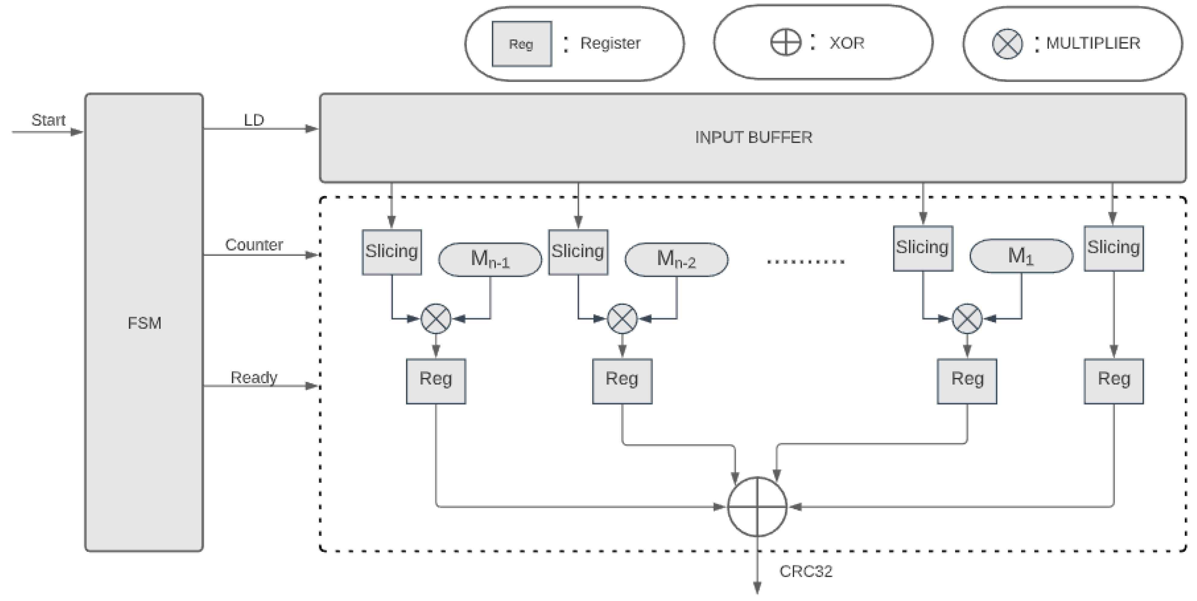
4. FPGA Implementation

To keep the system flexible, the algorithm is divided into several sub-modules: the multiplier unit, the slicing unit, and the finite state machine (FSM) unit. The FSM is the core unit of the system, and it plays an important role in scheduling and synchronizing other units. The overall architecture of the system is shown in Figure 6. The flowchart of the FSM is shown in Figure 6.
As shown in Figure 7, initially, the FSM is in the IDLE state waiting for a start signal to go from 0 to 1. When the FSM starts, in the first cycle, it asserts the LD signal to one to load the data into the input buffer and turn off the LD signal back to zero immediately in the next cycle. After the input message has been loaded into the buffer and hold valid during the process, the counter begins to count in the next cycle. The process iterates over K cycles where K is calculated as shown in the formula below:
K   =   M S × N ,
with M is the data buffer length and S is the number of slicing-by-N units. After the process ends, each output from a Slicing-by-N computation unit is multiplied with its corresponding modular matrix. The multiplication is carried out in single clock since the modular matrix is precomputed and can be realized with only XOR operation. Finally, the ready is asserted to 1, and the partial CRC results are loaded into the registers. The final CRC of the whole input is obtained by XORing all partial CRC results as mentioned in the previous section.

5. Experimental Results

Prior to the implementation on FPGA, we simulate the algorithm by using multi-threaded C++ program and verify the results by comparing it with the serial CRC algorithm. The hybrid algorithm passes all the test cases where data are from 128 KB to 2 MB with 256 KB increasement. In addition, we also measure the performance of the simulation. A linear congruential generator is used to generate input for various data lengths. Each test configuration is repeated 20 times, each time with different seeds for random testing. To cancel the noise in the performance measurement, we average 20 test cases of a given configuration. Figure 8 shows performance results. Figure 9 shows the comparison between Sarwate algorithm, Matrix Multiplication method, and the hybrid method to validate the effectiveness of parallel computing.
As expected, the CPU version could not achieve a speed factor equal to the number of threads used due to thread management overhead and other CPU resources sharing (e.g., data transfer, cache memory). Figure 10 below shows speed up achieved with the number of threads used in normalized time. Unlike a CPU, an FPGA is parallel in nature; therefore, it would be able to achieve speed-up factors approaching theoretical results.
To verify the functionality of the parallel CRC computational system, we synthesized and implemented the architecture on the ZEM5310 FPGA evaluation board from Opal Kelly Inc. (Portland, OR, USA). This board is a commercial, off-the-shelf FPGA board that contains a USB 3.0 driver and supports C++ packages. A test program has been written in C++ to generate the data, transfer the data to the FPGA via USB protocol, obtain the CRC results, and compare it with software computed CRC results. The experiment has successfully passed all the test cases. The test cases are similar to what we described in the experiment with CPU. The test system is described in Figure 11.
To analyze the effectiveness of the parallel CRC computational system, we measured the number of cycles against the number of logic elements needed to implement the algorithm on an FPGA platform for various data lengths. The logic element is defined as the smallest logic block of the FPGA family architecture which consists of a 4-input lookup table and a D-flipflop. All of the experiments are synthesized and measured by using Quartus compiler. Figure 12 below shows the measurement results with the system clock at 100 MHz. It is interesting to note that resource investment is only useful when the data length is sufficient long. For example, the number of cycles to compute the CRC does not reduce much in the case of 2 KB data length.

6. Conclusions and Future Work

In this paper, we have demonstrated the implementation of an efficient hybrid lookup table and matrix transformation algorithm for high throughput parallel computational unit on an FPGA platform. This algorithm will have significant applications in space-based remote sensing instrumentation by ensuring the signal integrity of the data. We also analyzed the throughput of the system vs. resource utilization for several cases and showed the effectiveness of the system versus data length. In the future, to further optimize the system, an advanced multi-port ROM topology can be used to reduce the number of logic elements and the possibility to use dual port Random-Access-Memory (RAM) as shared memory to transfer data from the resource to CRC module Another possible improvement is re-architecting the system to use pipelining where both data loading and CRC computation can be performed without the need of using the FSM.

Author Contributions

Writing–original draft, D.T.; Writing–review and editing, S.A., N.G. and G.N. All authors have read and agreed to the published version of the manuscript.

Funding

This research is funded by the NASA Grant and Cooperative Agreement Federal Award Identification No.: 80NSSC20M0017.

Conflicts of Interest

The authors declare no conflict of interest.

References

  1. Aslam, S.; Amato, M.; Bowles, N.; Calcutt, S.; Hewagama, T.; Howard, J.; Howett, C.; Hsieh, W.-T.; Hurford, T.; Hurley, J.; et al. Dual-telescope multi-channel thermal-infrared radiometer for outer planet fly-by missions. Acta Astronautica 2016, 128, 628–639. [Google Scholar] [CrossRef]
  2. Aslam, S.; Achterberg, R.K.; Calcutt, S.B.; Cottini, V.; Gorius, N.J.; Hewagama, T.; Irwin, P.G.; Nixon, C.A.; Quilligan, G.; Roos-Serote, M.; et al. Advanced Net Flux Radiometer for the Ice Giants. Space Sci. Rev. 2020, 216, 11. [Google Scholar] [CrossRef]
  3. Mousis, O.; Atkinson, D.H.; Cavalié, T.; Fletcher, L.N.; Amato, M.J.; Aslam, S.; Ferri, F.; Renard, J.-B.; Spilker, T.; Venkatapathy, E.; et al. Scientific rationale for Uranus and Neptune in situ explorations. Planet. Space Sci. 2018, 155, 12–40. [Google Scholar] [CrossRef] [Green Version]
  4. Lin, B.-C. System and Method for Storing a Data File Backup. U.S. Patent US7533291B2, 12 May 2009. [Google Scholar]
  5. Hu, T.; Zheng, M.; Tan, J.; Zhu, L.; Miao, W. Intelligent photovoltaic monitoring based on solar irradiance big data and wireless sensor networks. Ad. Hoc. Netw. 2015, 35, 127–136. [Google Scholar] [CrossRef]
  6. Elahi, A.; Gschwender, A. Zigbee Wireless Sensor and Control Network; Prentice Hall Press: Upper Saddle River, NJ, USA, 2009. [Google Scholar]
  7. Berger, C. Automating Acceptance Tests for Sensor- and Actuator-Based Systems on the Example of Autonomous Vehicles; Shaker Verlag Gmbh: Aachen, Germany, 2010. [Google Scholar]
  8. Brito, J.; Gomes, T.; Miranda, J.; Monteiro, L.; Cabral, J.; Mendes, J.; Monteiro, J.L. An Intelligent Home Automation Control System Based on a Novel Heat Pump and Wireless Sensor Networks. In Proceedings of the 2014 IEEE 23rd International Symposium on Industrial Electronics (ISIE), Istanbul, Turkey, 1–4 June 2014; pp. 1448–1453. [Google Scholar] [CrossRef]
  9. Küçük, G.; Başaran, C. Reducing Energy Consumption of Wireless Sensor Networks through Processor Optimizations. J. Comput. 2007, 2, 67–74. [Google Scholar] [CrossRef]
  10. Wu, H. A Brief Overview of CRC Implementation for 5G NR. Available online: https://www.intechopen.com/online-first/a-brief-overview-of-crc-implementation-for-5g-nr (accessed on 20 October 2020).
  11. Wesley Peterson, W. Available online: https://en.wikipedia.org/wiki/W._Wesley_Peterson (accessed on 20 October 2020).
  12. Sarwate, D.V. Computation of cyclic redundancy checks via table look-up. Commun. ACM 1988, 31, 1008–1013. [Google Scholar] [CrossRef]
  13. Kounavis, M.E.; Berry, F.L. Novel Table Lookup-Based Algorithms for High-Performance CRC Generation. IEEE Trans. Comput. 2008, 57, 1550–1560. [Google Scholar] [CrossRef]
  14. Derby, J. High-speed CRC computation using state-space transformations. In Proceedings of the GLOBECOM’01. IEEE Global Telecommunications Conference (Cat. No.01CH37270), San Antonio, TX, USA, 25–29 November 2001; pp. 166–170. [Google Scholar] [CrossRef]
  15. Kounavis, M.E.; Berry, F.L. A Systematic Approach to Building High Performance Software-Based CRC Generators. In Proceedings of the 10th IEEE Symposium on Computers and Communications (ISCC’05), Cartagena, Murcia, Spain, 27–30 June 2005; pp. 855–862. [Google Scholar] [CrossRef]
  16. Mitra, J.; Nayak, T. Reconfigurable very high throughput low latency VLSI (FPGA) design architecture of CRC 32. Integration 2017, 56, 1–14. [Google Scholar] [CrossRef]
  17. Henriksson, T.; Eriksson, H.; Nordqvist, U.; Larsson-Edefors, P.; Liu, D. VLSI implementation of CRC-32 for 10 Gigabit Ethernet. In Proceedings of the ICECS 2001, 8th IEEE International Conference on Electronics, Circuits and Systems (Cat. No.01EX483), Malta, Malta, 2–5 September 2001; p. 4. [Google Scholar]
  18. Chi, M.; He, D.; Liu, J. Exploring Various Levels of Parallelism in High-Performance CRC Algorithms. IEEE Access 2019, 7, 32315–32326. [Google Scholar] [CrossRef]
Figure 1. (a) Mechanical drawing of the IG-NFR instrument concept; (b) IG-NFR accommodated inside the probe.
Electronics 10 00866 g001
Figure 2. System block diagram. The CRC error check will run on the processor card shown in the main electronics box.
Electronics 10 00866 g002
Figure 3. Partial structure of the linear shift register for G(x).
Electronics 10 00866 g003
Figure 4. Superposition property of the CRC generation method.
Electronics 10 00866 g004
Figure 5. Hybrid system using both slicing-by-N and matrix transformation.
Electronics 10 00866 g005
Figure 6. Overall architecture of the parallel CRC computational system. For clarity, not all connections are shown. The counter signal and the ready signal are distributed to all slicing unit and register unit correspondingly.
Electronics 10 00866 g006
Figure 7. (a) FSM of the architecture and (b) Implementation of the Slicing-by-N computation unit.
Electronics 10 00866 g007
Figure 8. Performance results of a multi-threaded C++ program.
Electronics 10 00866 g008
Figure 9. Comparison between three methods, hybrid methods running with two threads.
Electronics 10 00866 g009
Figure 10. Measured normalized operating time vs. threads for 2 MB data.
Electronics 10 00866 g010
Figure 11. Simplified diagram of the test system.
Electronics 10 00866 g011
Figure 12. Number of cycles vs. logic elements for different data lengths.
Electronics 10 00866 g012
Table 1. IG-NFR data.
NameNumber of BitsNumber of ChannelsTotalComment
Thermopile Data + Time Stamp
Thermistor data on thermopile
Hot Target Temperature
328256Science Data
168128Science Data
12112Thermal data
Fan-out board Temperature
Vessel Temperature
12112Thermal data
12112Thermal data
Windows Temperature
Cold Target Temperature
LED status
Motor Position
12112Thermal data
12112Thermal data
111Auxiliary data, 1 bit for ON/OFF
313Auxiliary data, 3 bits for 7 positions
Survival Heater Status
Thermopile Data + Time Stamp
111Auxiliary data, 1 bit for ON/OFF
328256Science Data
Publisher’s Note: MDPI stays neutral with regard to jurisdictional claims in published maps and institutional affiliations.

