Abstract
Temperature has an important effect on the battery model. A dual-polarization equivalent circuit model considering temperature is established to quantify the effect of temperature, and the initial parameters of the model are identified through experiments. To solve the defect of preset noise, the H-infinity filter algorithm is used to replace the traditional extended Kalman filter algorithm, without assuming that the process noise and measurement noise obey Gaussian distribution. To eliminate the influence of battery aging on SOC estimation, and considering the different time-varying characteristics of the battery states and parameters, the dual time scale double H-infinity filter is used to jointly estimate the revised SOC and available capacity. The simulation results at two temperatures show that, compared with the single time scale, the double time scale double H-infinity filter reduces the simulation time by nearly 90% under the premise that the accuracy is almost unchanged, which proves that the proposed joint estimation algorithm has the dual advantages of high precision and high efficiency.
1. Introduction
An accurate state of charge (SOC) and available capacity estimation is an important function of a battery management system (BMS). The battery model is an important factor affecting estimation accuracy. The equivalent circuit model is a kind of lithium-ion battery model with the most extensive application and research results. Hu et al. [1] analyzed and compared the differences between twelve different equivalent circuit models from the three dimensions of model accuracy, operation complexity, and robustness. Based on the first-order RC equivalent circuit model, Liaw et al. [2,3] analyzed and identified the parameters from two aspects: external characteristics of charge and discharge and electrochemical impedance spectrum. Xiong et al. [4] estimated the SOC based on the second-order RC equivalent circuit model and obtained precise estimation results. The fractional-order model established by Hu et al. [5] also has high accuracy, and the SOC estimation error obtained under different working conditions can be kept within 0.02. Liu et al. [6] took full advantage of the strong robustness of the fractional-order model and estimated SOP based on a second-order fractional-order model, and obtained ideal estimation results. However, most of the equivalent circuit models in the existing research are established under constant temperature, and only a few consider the influence of temperature. Wang et al. [7] considered the influence of temperature and battery capacity in modeling, and a particle filter was used to estimate SOC at different ambient temperatures. Huang et al. [8] established a power-input electrothermal coupling model by taking power as input. Xu et al. [9] studied the SOC estimation at different ambient temperatures through the electrothermal coupling model. Aung et al. [10] also studied the effects of charge and discharge ratio and temperature on battery parameters and realized real-time updates of battery parameters.
In terms of SOC estimation of the lithium-ion battery, model-based Kalman filter series are the most widely used algorithms at present. Based on the fractional-order model, references [11,12] used a series of Kalman filter algorithms to realize the accurate estimation of SOC. Wang et al. [13] used a double extended Kalman filter to estimate SOC under constant current and dynamic discharge conditions. Xu et al. [14] used machine learning method for modeling and sigma point Kalman filter to estimate SOC. Zhang et al. [15] used the improved adaptive Kalman filter algorithm to enhance the robustness of SOC estimation. Tian et al. [16] estimated SOC by combining long and short-term memory (LSTM) neural network and adaptive cubature Kalman filter, and the maximum error was guaranteed within 4%. The Kalman filter series algorithms require that the noise must meet the Gaussian distribution, but affected by various factors, the vehicle battery management system is difficult to obtain prior knowledge of noise. Lin et al. [17] used H infinite filtering algorithm to accurately estimate the battery energy state without assuming the statistical characteristics of noise. Similarly, Li et al. [18] used an H-infinity filter algorithm to estimate SOC and achieved relatively ideal estimation results.
In addition, there are two definitions of SOC at present. The first definition takes the rated capacity as the denominator of SOC, and the other definition selects the maximum capacity as the denominator. However, regardless of which definition, the denominator of SOC is a fixed value. However, with the aging of the battery and capacity attenuation, the SOC does not reach the set value and the battery can no longer charge and discharge, which reduces the user experience [19]. This can be avoided if the available capacity is used as the denominator.
Plett [20] first proposed to use the extended Kalman filter algorithm to construct a dual filter framework. One filter is used for parameter estimation and the other filter is used for state estimation so as to jointly estimate the SOC and available capacity of the battery. Hua et al. [21] proposed a double nonlinear predictive filter for the SOC and capacity estimation of batteries. The capacity is regarded as a component of the model parameter vector and estimated together with the SOC. The feasibility of this method is verified by using the UDDS conditions. The robustness of the algorithm is improved by updating the relevant model parameters, but the two filters work at the same time, which reduces the stability of the algorithm and increases the computational burden [22,23].
Although many achievements have been made in the joint estimation of SOC and available capacity of a lithium-ion battery, there are still some problems that have not been fully solved. On the one hand, the model parameters and states may produce cross-interference during the joint estimation process, which will affect the estimation results. On the other hand, the battery states have fast time-varying characteristics, and the parameters have slow time-varying characteristics. Using the same time scale will cause the model parameters to be updated too frequently, which will reduce the stability of the estimation algorithm, increase the operation load and reduce the response speed.
To sum up, in Section 2, to quantify the effect of temperature on the battery model, a dual-polarization equivalent circuit model considering temperature was established, and the initial parameters of the model were obtained through experiments. In Section 3, in order to solve the problem that the Kalman filter series algorithms need to preset noise, the H-infinity filter was used to estimate SOC; at the same time, in order to avoid the impact of battery aging on SOC estimation, another time-scale H-infinity filter was used to estimate the available capacity, which realized the dual guarantee of operation efficiency and estimation accuracy and the joint estimation of SOC and available capacity.
2. Battery Modeling
2.1. Dual-Polarization Equivalent Circuit Model Considering Temperature
The temperature has a great influence on the performance and service life of the battery. At low temperature, the chemical reaction inside the battery is slow, which is easy to increase the internal resistance and reduce the capacity; at high temperature, the chemical reaction is intense, which is easy to cause rapid self-discharge. Therefore, it is necessary to quantify the effect of temperature on the battery. The parameters in the dual-polarization model without considering temperature will not change with temperature, which makes the temperature robustness of the model very poor. The dual-polarization model considering temperature is used to quantitatively express the temperature dependence of all parameters of the battery model, so as to improve the robustness of the model.
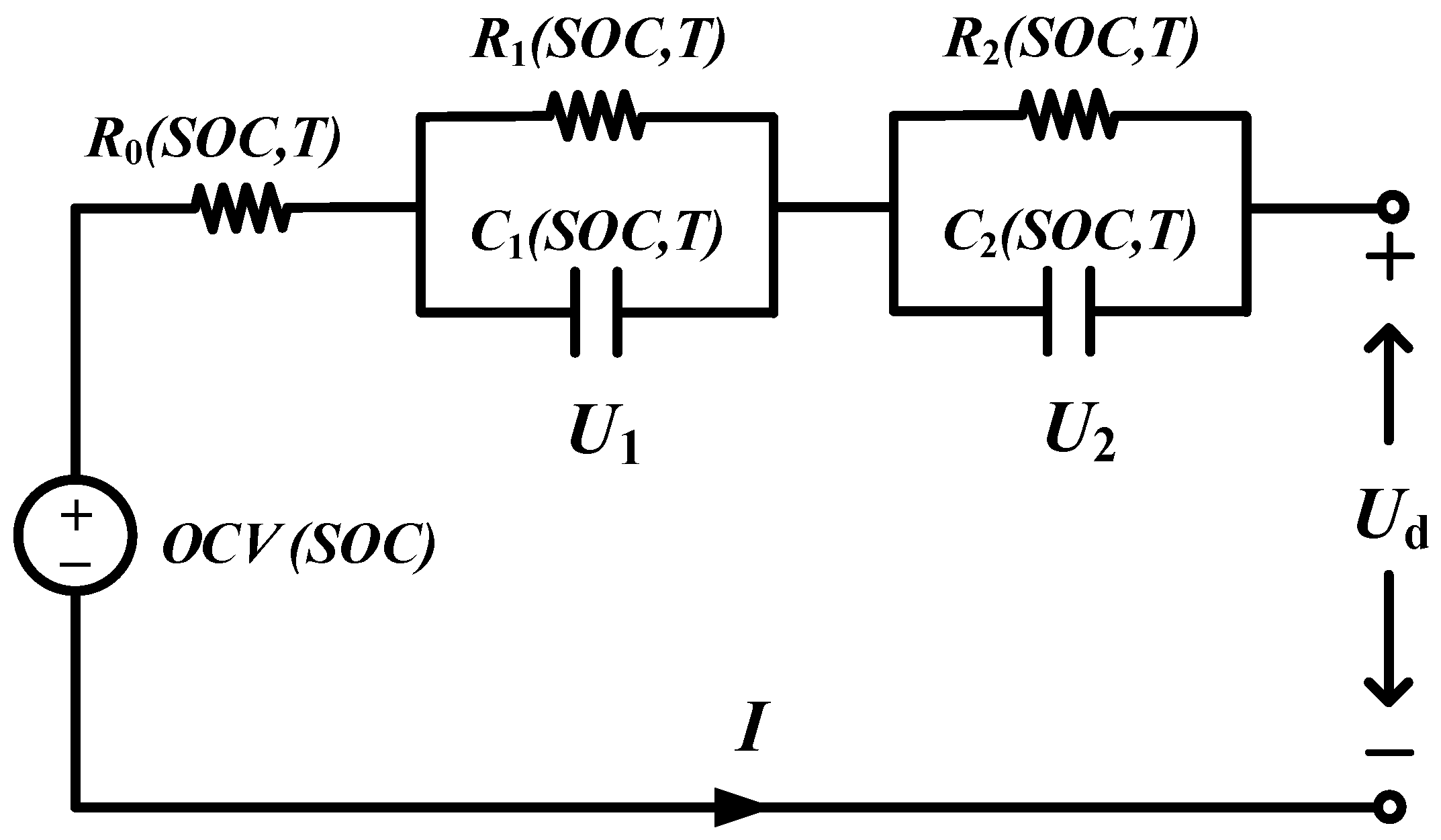
The schematic diagram of the dual-polarization equivalent circuit model considering temperature is shown in Figure 1. Wherein, Ud represents the terminal voltage of the battery, V; I is current (positive for charge and negative for discharge), A; OCV is the open circuit voltage, V; R0 is ohmic internal resistance, Ω; R1 and R2 are polarization internal resistance, Ω; C1 and C2 are polarization capacitors, F; T is ambient temperature, °C. R0, R1, R2, C1, and C2 are all temperature-dependent. The polarization internal resistance and polarization capacitance are used to represent the polarization phenomenon of the battery, and the corresponding voltages are U1 and U2, respectively, V.
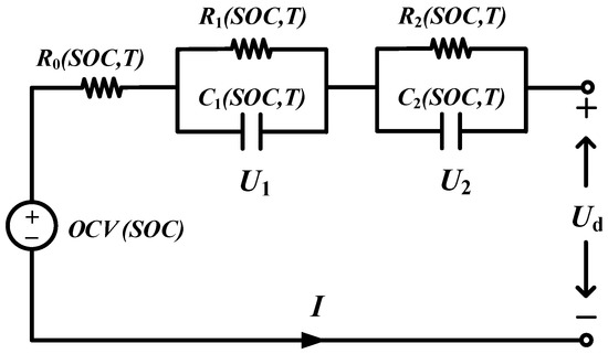
Figure 1.
The schematic diagram of the dual-polarization equivalent circuit model considering temperature.
According to Kirchhoff’s law of current and voltage, the dynamic equation of the model can be expressed as:
where and represent the rate of change of voltages and , respectively.
The SOC of the battery can be expressed as [16]:
where, SOC(t) and SOC(t0) represent the values of SOC at time t and t0 respectively; η is the charge and discharge efficiency, which is usually taken as 1 during discharge and 0.98 during charge; QN represents the rated capacity of the battery, Ah.
The definition of SOC is revised in this study:
where Q is the actual available capacity of the battery.
Set the sampling time as and discretize Equations (1) and (2) to obtain:
The parameters to be identified in the model are:
2.2. Initial Parameter Identification of Model
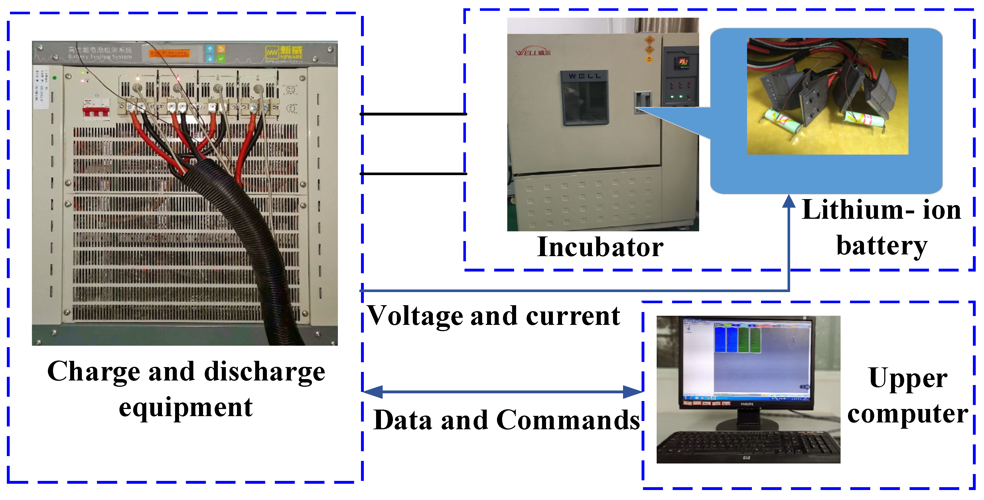
The battery test system used is shown in Figure 2.
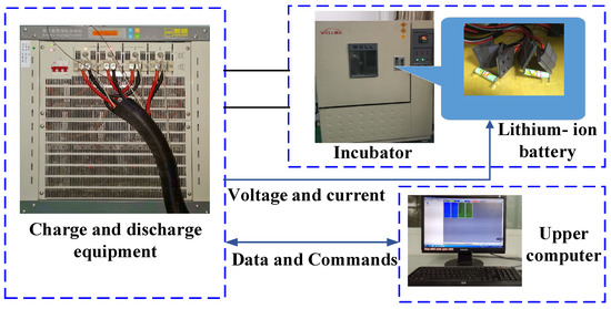
Figure 2.
Battery test system.
The test object is 18,650 ternary lithium-ion battery. The specific parameters are shown in Table 1.

Table 1.
Main performance parameters of 18,650 cell.
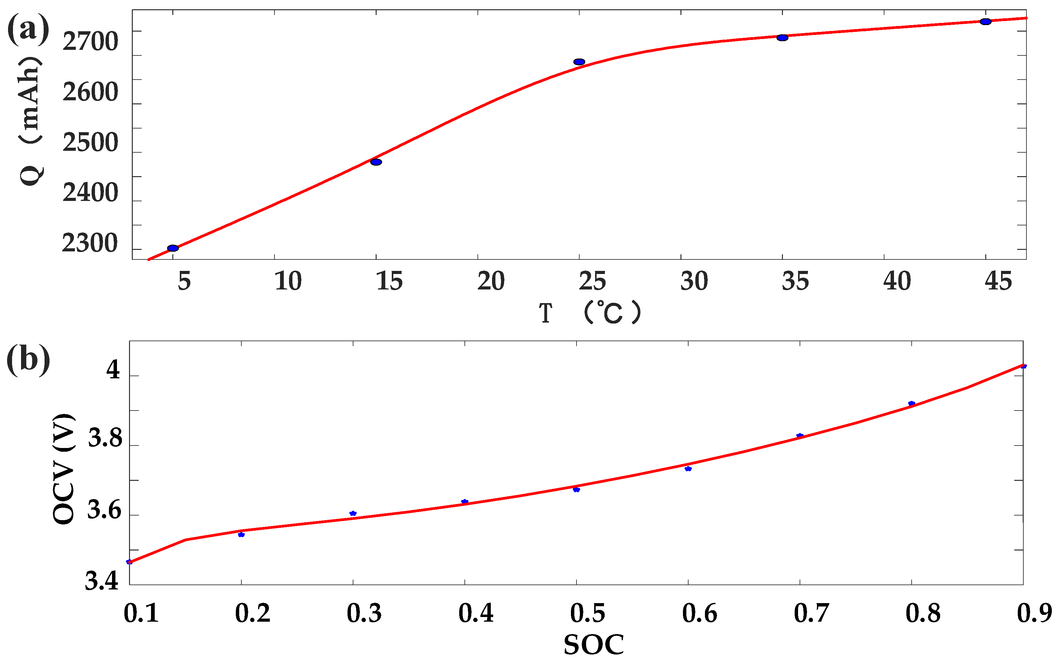
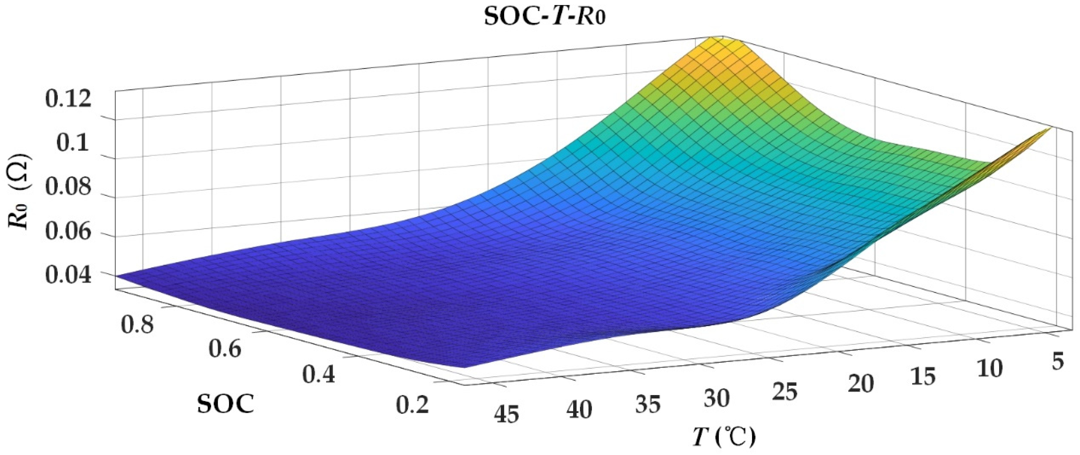
The basic performance test of the battery includes static capacity test (SCT) for measuring the initial capacity of the battery, double pulse test for obtaining SOC-OCV curve, hybrid pulse power characteristic (HPPC) for battery resistance-capacitance parameter identification, and dynamic condition test including dynamic stress test (DST) test and federal urban driving schedule (FUDS). The identification results are shown in Figure 3, Figure 4 and Figure 5. Refer to [9] for specific identification methods.
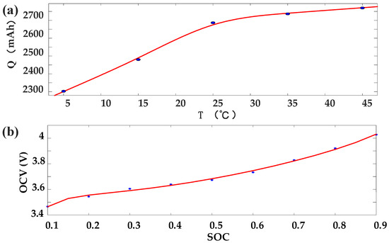
Figure 3.
(a) The fitting curve of the initial available capacity and temperature; (b) The SOC-OCV fitting curve.
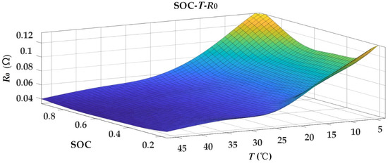
Figure 4.
The mapping between SOC, temperature, and ohmic resistance.
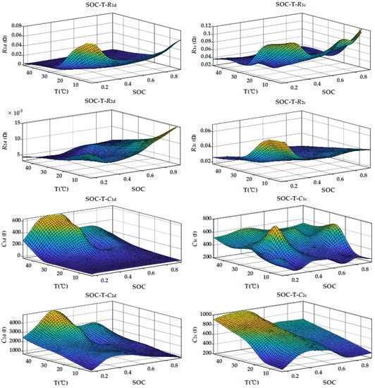
Figure 5.
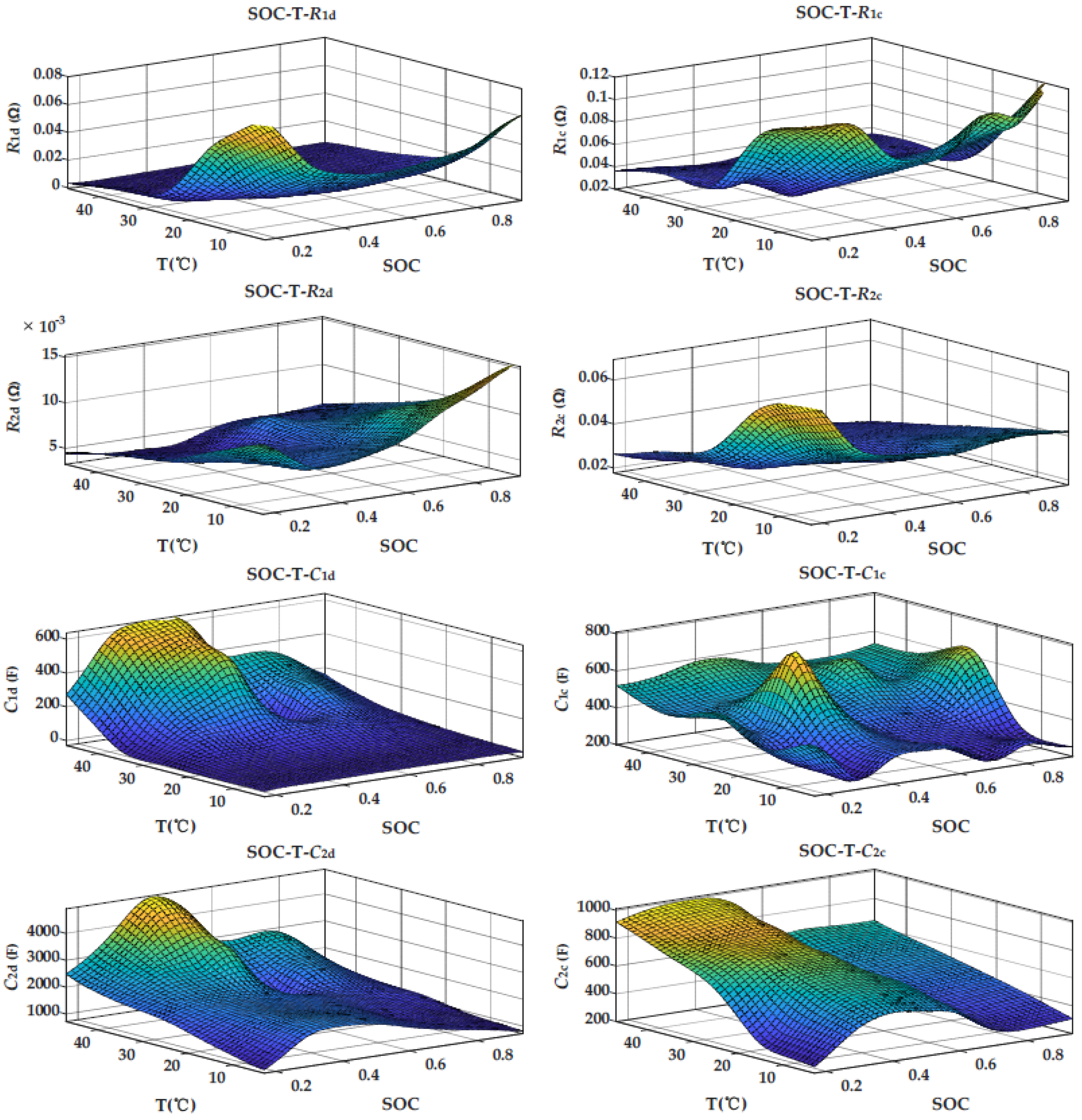
The identification results of R1, R2, C1, and C2, where the left column is discharge and the right column is charge.
It should be noted that through the double pulse test at different temperatures, it was found that the OCV of the battery fluctuates little with temperature. Therefore, in order to facilitate calculation, ignoring the influence of temperature on OCV, the OCV at 25 °C ambient temperature was used to approximate the OCV at all temperatures, and the final OCV was the average value of OCV measured under discharge pulse and charging pulse, as shown in Table 2. The empirical formula, as shown in Equation (6), was used to fit the relationship curve between SOC and OCV [24].

Table 2.
OCV measurement results at 25 °C.
It can be seen that the values of the four polarization parameters, R1, R2, C1, and C2, change under different temperatures, SOC, and charge-discharge directions. The initial values of polarization parameters were determined by looking up the table according to the current ambient temperature, SOC, and charge-discharge direction of the battery. For ohmic internal resistance R0, since the influence of charge-discharge direction was very small, the influence of ambient temperature and SOC were only considered.
3. Joint Estimation of SOC and Available Capacity
3.1. Overview of Joint Estimation Algorithms
Among the model-based SOC estimation algorithms, Kalman series filter algorithm has the characteristics of high accuracy and a small amount of calculation, but it also has some limitations:
- (1)
- The process noise and measurement noise are required to be a white noise obeying Gaussian distribution. However, in practical application, the vehicle battery system will be affected by complex environmental factors, so it is difficult to obtain the prior knowledge of noise;
- (2)
- The estimation accuracy has a strong correlation with the accuracy of the model. When the model accuracy is not enough or the model accuracy gradually decreases with the change of dynamic conditions, the estimation error of this method will be larger and larger.
In order to overcome the demands of Kalman filter algorithms on noise and accurate model, a H-infinity filter algorithm with lower requirements on model accuracy and stronger robustness to various noise disturbances was introduced.
The following discrete linear systems are established:
where represents the state variable; represents the input variable; represents the output variable; is the state matrix; is the input matrix; is the observation matrix; is the input-output matrix; is process noise, generated by modeling error; is the measurement noise, generated by the measurement noise of current and voltage.
In order to avoid the situation that EKF algorithm needs to assume noise information in advance, the H-infinity filtering algorithm defines the cost function J:
where P0 represents the initial state error covariance matrix; Qk and Rk represent the process noise covariance matrix and the measurement noise covariance matrix; Sk is designed according to the designer’s attention to each state quantity.
It can be seen from Equation (8) that the cost function of the H-infinity filter is a proportional value, whose denominator is related to the error of the system and numerator is related to the error of the estimated value. The main purpose of establishing the cost function is to reflect the proportional relationship between estimation error and noise interference. It is difficult to directly minimize the cost function, so it is necessary to select a performance boundary, that is:
J < 1/θ
In order to get the optimal result, appropriate need to be founded to minimize the cost function. Assuming that nature is our opponent (there is interference), it hopes to maximize the cost function through special , and . Therefore, when , and make the cost function maximum, it is necessary to find an appropriate to make the cost function minimum. By reintegrating Equations (8) and (9), combining Equation (7), the following can be obtained:
Therefore, the H-infinity filter can be simply described as: when , and make J* maximum, find a suitable to make J* minimum. From the derivation process, the H-infinity filter does not assume the statistical characteristics of noise in advance, which is its biggest advantage over the Kalman filter.
By finding the minimum J*, the recursive relationship shown in Equation (11) can be obtained.
In addition, the battery state has fast time-varying characteristics, while the parameters have slow time-varying characteristics. If the battery state and parameters are estimated with the same time scale, the stability of the estimation algorithm will be reduced, the operation load will be increased, and the response speed will be reduced because the parameters change too frequently. Therefore, this study uses two different time scales to jointly estimate SOC and parameters, including available capacity. For SOC, the micro time scale is used for estimation, and the parameter correction is carried out under the macro time scale. The two-time scales are relatively fixed, and the macro scale is a fixed multiple of the micro-scale.
Establish a nonlinear discrete system in two time scales:
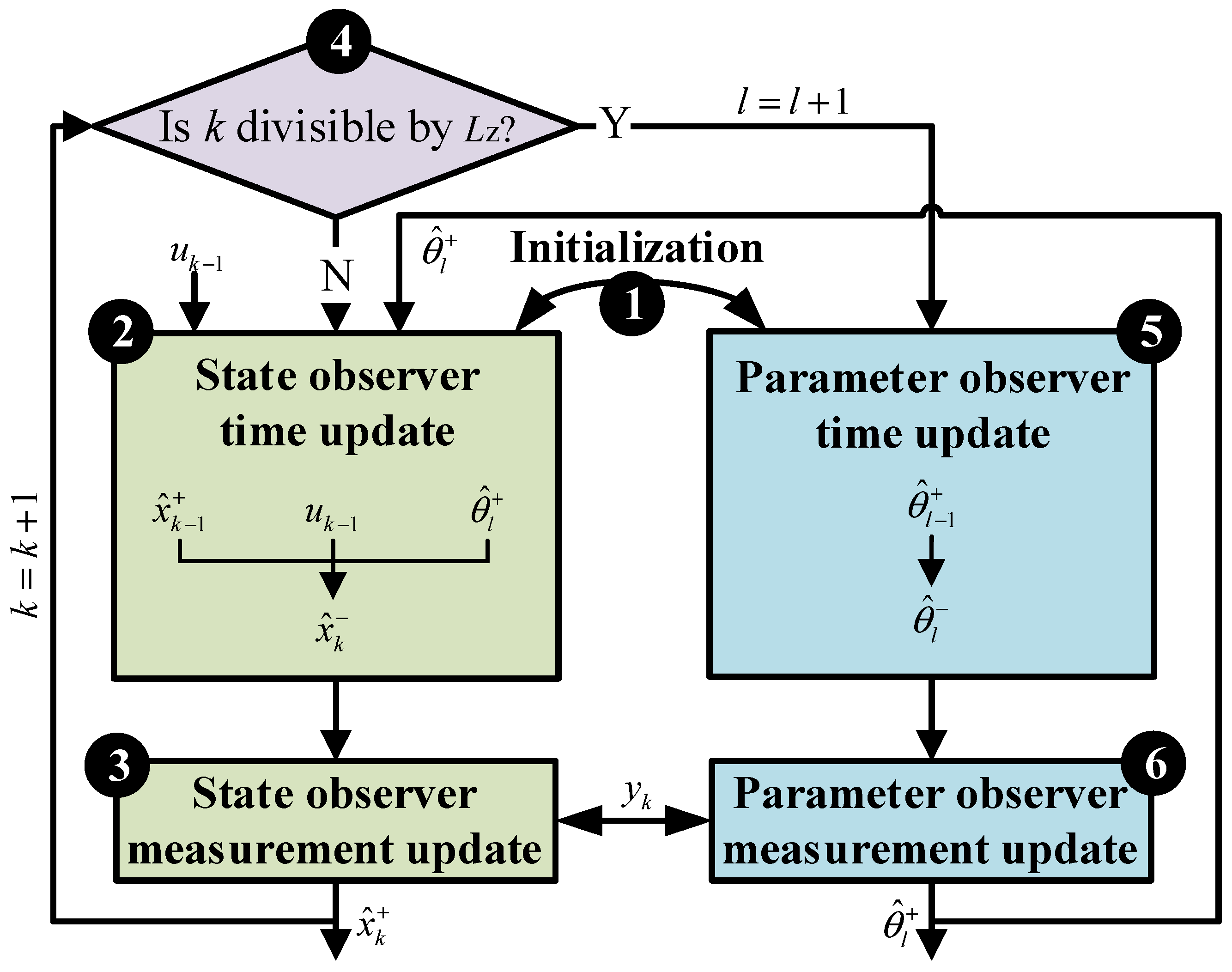
where, represents parameter variable; is the parameter white noise; The noise covariance matrix in the state estimation is expressed by , , , and , and the noise covariance matrix in the process of parameter identification is expressed by , , , and . k represents the micro time scale of state estimation, that is, state estimation is performed once at each sampling time point; l represents the macro time scale of parameter estimation, which is numerically equal to the product of k times . is the scale conversion limit, that is, parameter estimation is carried out every sampling time points; The schematic diagram of dual time scale dual filter algorithm is shown in Figure 6.
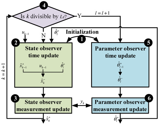
Figure 6.
Schematic diagram of dual time scale double H-infinity filter algorithm.
The specific calculation process of dual time scale double H-infinity filtering algorithm is as follows:
(1) Establish a nonlinear discrete system:
Define:
(2) Initialize:
(3) Time update of status:
(4) Measurement update of status:
(5) Time scale update: k = k + 1, prepare the state estimation at time k and judge whether k can be divided by Lz. If so, l = l + 1, and continue to the next step. Otherwise, return to step (2).
(6) Time update of parameters:
(7) Measurement update of parameters:
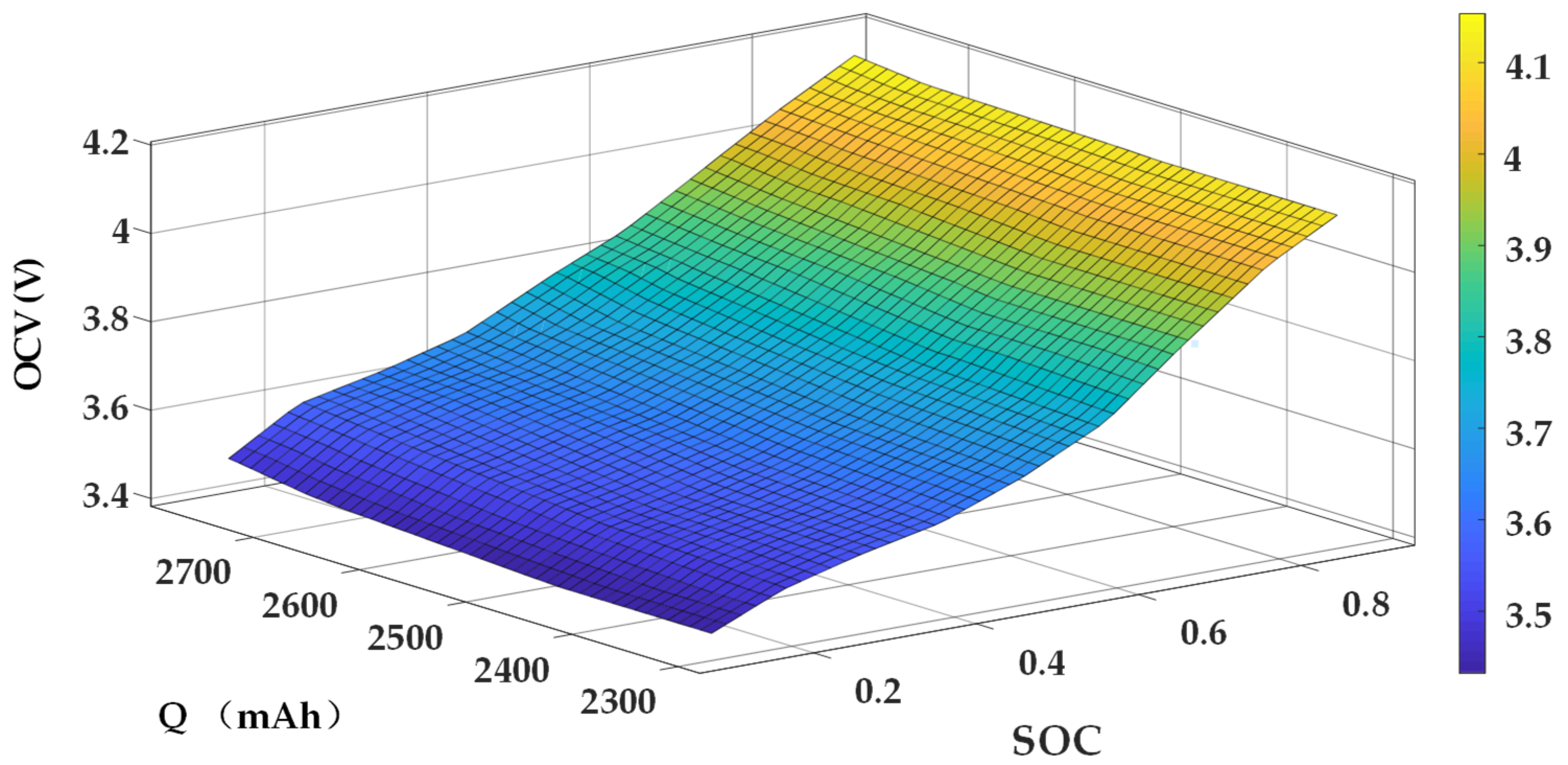
It should be noted that according to the new definition of SOC, the relationship between SOC and OCV will change in the whole life cycle of the battery. For example, when the available capacity of the battery decreases, the OCV under the same SOC will change compared with the new battery. Considering this, the SOC-Q-OCV mapping is established, as shown in Figure 7, and the fitting relationship is shown in Equations (24) and (25).
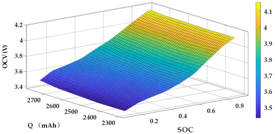
Figure 7.
The mapping between SOC, available capacity, and OCV.
, and are quadratic functions of available capacity Q.
where is a 5 × 3 coefficient matrix.
3.2. Simulation and Experimental Verification
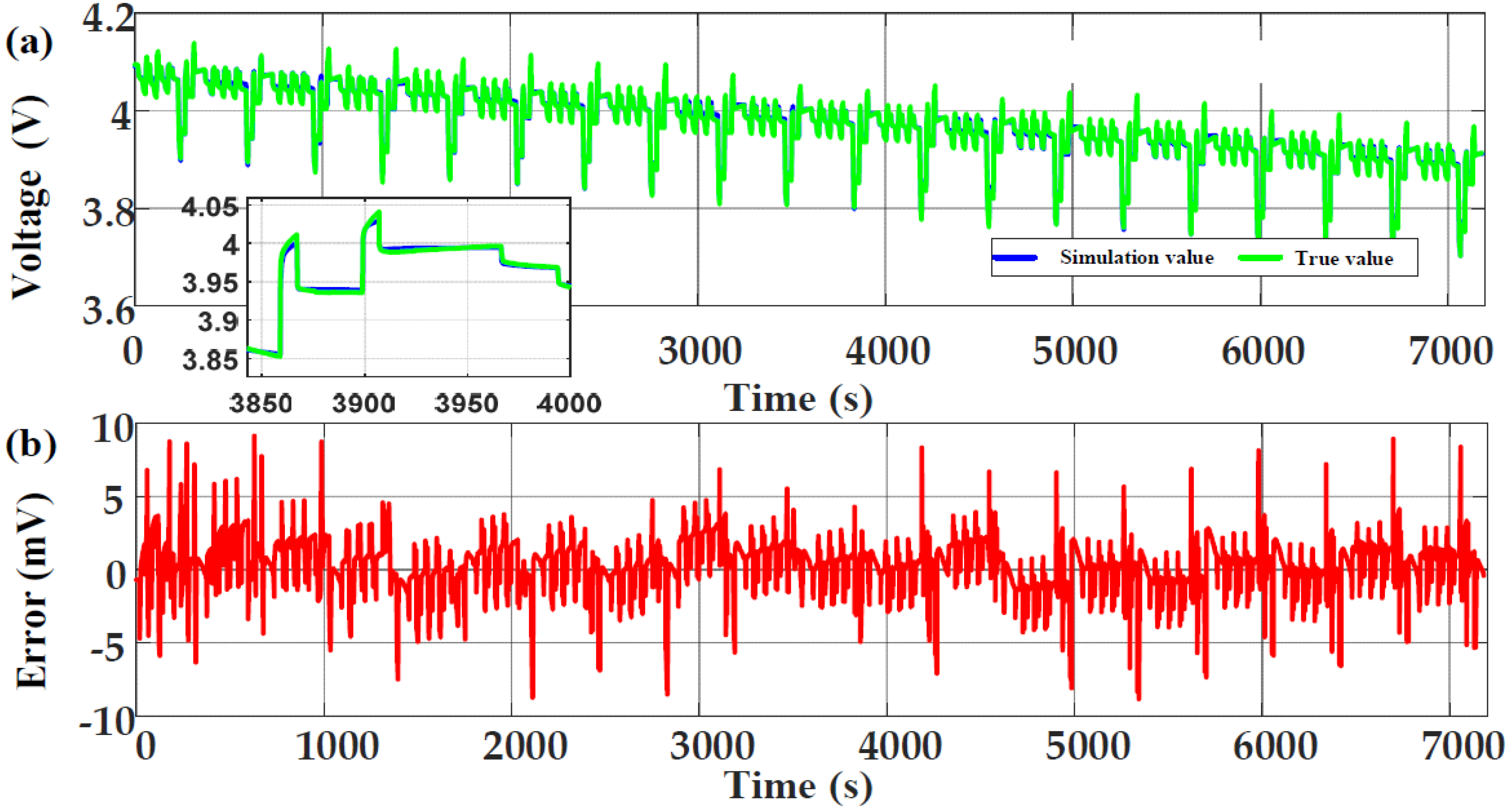
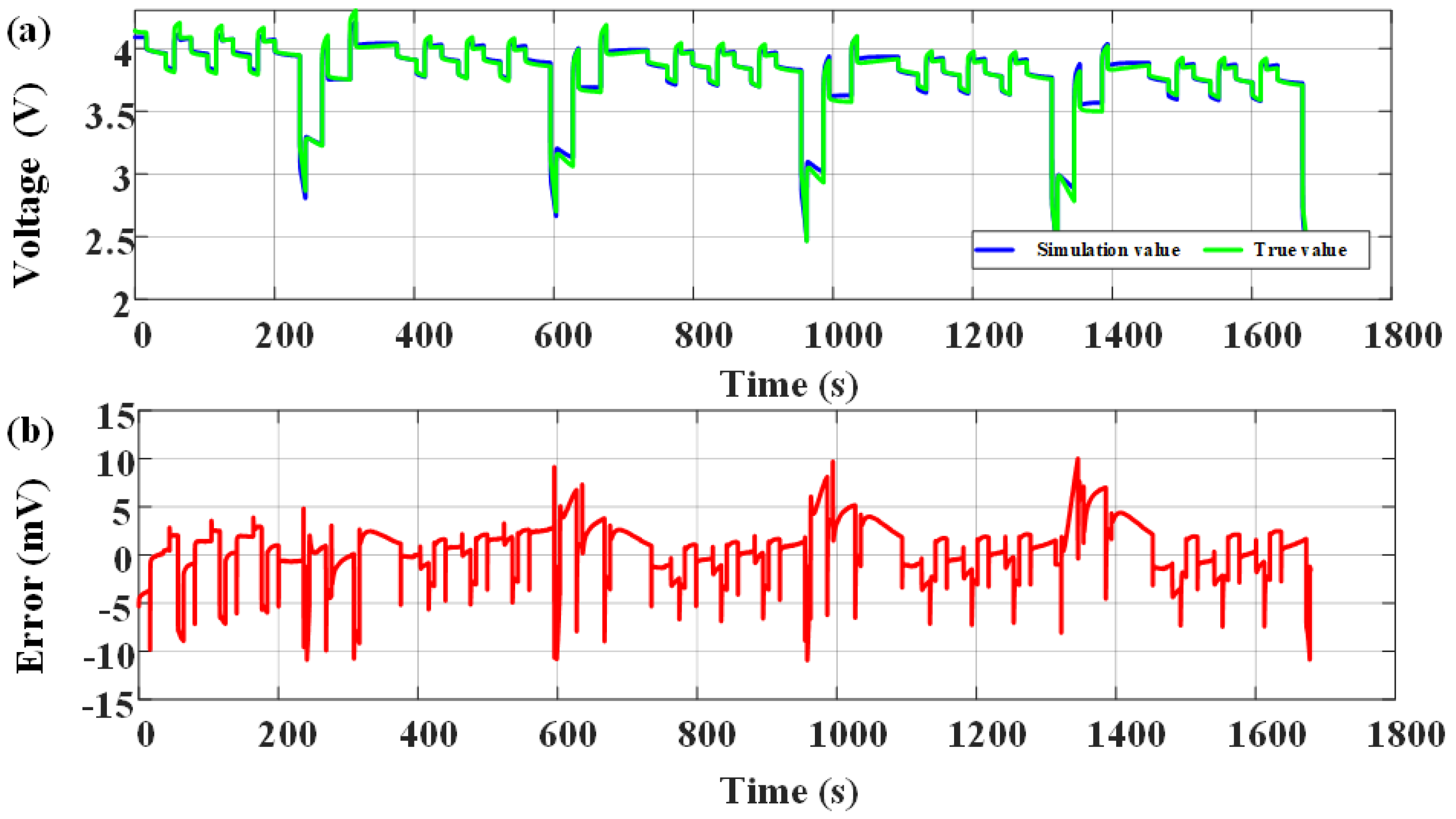
After 200 cycles of charge and discharge, the DST working condition data at 25 °C ambient temperature were used for simulation verification. At this time, the real value of the available capacity of the battery was 2560 mAh, and the initial real value of SOC was 0.95. The initial value of SOC in the algorithm was set to 0.85, and the initial values of each parameter were determined according to the identification results in Section 2.2. After comparison, for balancing accuracy and complexity, the scale conversion limit of dual time scale was set to 30 s. The model simulation results are shown in Figure 8, and the estimation results of SOC and available capacity are shown in Figure 9 and Figure 10.
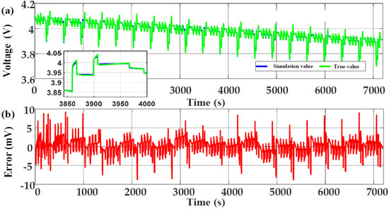
Figure 8.
Model simulation results in DST condition: (a) Comparison of simulation voltage and true voltage; (b) The error of simulation voltage.

Figure 9.
Estimation results of SOC in DST condition: (a) Comparison of estimated SOC and true SOC; (b) The error of estimated SOC.

Figure 10.
Estimation results of available capacity in DST condition: (a) Comparison of estimated available capacity and true available capacity; (b) The error of estimated available capacity.
In order to further verify the effectiveness at low temperature, the DST working condition data at 5 °C ambient temperature after 300 cycles are used for simulation verification. At this time, the real value of the available capacity of the battery is 2207 mAh, and the initial real value of SOC is 0.95. The initial value of SOC in the algorithm is set to 0.85, and the initial values of each parameter are determined according to the identification results in Section 2.2. The model simulation results are shown in Figure 11 and the estimation results of SOC and available capacity are shown in Figure 12 and Figure 13.
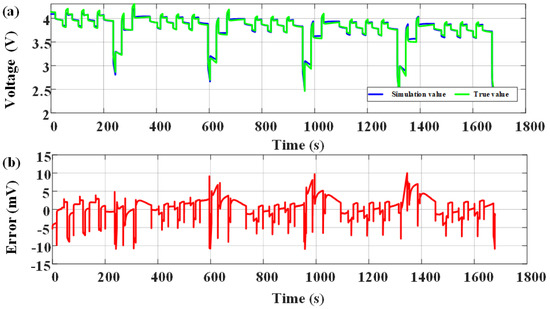
Figure 11.
Model simulation results in DST condition under low temperature environment: (a) Comparison of simulation voltage and true voltage; (b) The error of simulation voltage.

Figure 12.
Estimation results of SOC in DST condition under low temperature environment: (a) Comparison of estimated SOC and true SOC; (b) The error of estimated SOC.

Figure 13.
Estimation results of available capacity in DST conditions under a low-temperature environment: (a) Comparison of estimated available capacity and true available capacity; (b) The error of estimated available capacity.
At the same time, the single time scale double H-infinity filter was used for simulation analysis; that is, SOC estimation and parameter estimation used the same time scale. All the above results are summarized in Table 3, Table 4 and Table 5.

Table 3.
Simulation error of dual time scale algorithm.

Table 4.
Simulation error of single scale algorithm.

Table 5.
Comparison of calculation time between two algorithms.
The results show that the model error, SOC estimation error, and available capacity estimation error are in acceptable range whether single time scale or dual time scale. The model error and SOC estimation error obtained by single time scale algorithm are slightly lower than those of double time scale. For available capacity, the accuracy of the two is almost the same. However, the simulation time of dual time scale double H-infinity filter is nearly 90% less than that of single time scale, which greatly improves the operation efficiency.
4. Conclusions
Firstly, to quantify the influence of temperature on battery model parameters, a dual-polarization equivalent circuit model considering temperature is established, and the initial parameters are obtained through experiments. The verification results show that the maximum error of the model is only 12 mV, even at low temperature. Based on the model, a dual time scale double H-infinity filter algorithm is proposed to jointly estimate the revised SOC and available capacity. Compared with the Kalman filter series algorithms, H-infinity filter does not need to assume noise. Besides, The selection of double time scale not only ensures the estimation accuracy, making the SOC estimation error and available capacity estimation error almost the same as that of single time scale, which can be maintained within 4% and 52 mAh even at low temperature, but also shortens the simulation time by nearly 90%, which has higher engineering application value.
In future research, the battery model will be further improved. The fractional-order model will be used to realize the algorithm proposed in this study, and coupled with the thermal model to further accurately quantify the influence of temperature. In addition, the filtering algorithm will be combined with deep learning to further improve the estimation accuracy of parameters and states, and lower temperature is used to verify the algorithm.
Author Contributions
Conceptualization, B.H., M.H. and C.L.; methodology, B.H. and L.L.; software, C.L. and L.L.; validation, M.H., G.J. and H.Y.; formal analysis, B.H. and C.L.; investigation, B.H. and G.J.; data curation, C.L. and L.L.; writing—original draft preparation, B.H., M.H. and H.Y.; writing—review and editing, B.H. and C.L.; visualization, H.Y.; supervision, M.H. and L.L.; project administration, M.H. and G.J. All authors have read and agreed to the published version of the manuscript.
Funding
This research was funded by the National Natural Science Foundation of China under grant 52072053, the Foundation of Artificial Intelligence Key Laboratory of Sichuan Province under grant 2020RYY01, and the Science and Technology Department of Sichuan Province under grant 2021YFG0050.
Conflicts of Interest
The authors declare no conflict of interest.
References
- Hu, X.; Li, S.; Peng, H. A comparative study of equivalent circuit models for Li-ion batteries. J. Power Sources 2012, 198, 359–367. [Google Scholar] [CrossRef]
- Liaw, B.Y.; Nagasubramanian, G.; Jungst, R.G.; Doughty, D.H. Modeling of lithium ion cells—A simple equivalent-circuit model approach. Solid State Ion. 2004, 175, 835–839. [Google Scholar] [CrossRef]
- Dubarry, M.; Vuillaume, N.; Liaw, B.Y. From single cell model to battery pack simulation for Li-ion batteries. J. Power Sources 2009, 186, 500–507. [Google Scholar] [CrossRef]
- Xiong, R.; Sun, F.C.; He, H.W. Data-driven State-of-Charge estimator for electric vehicles battery using robust extended Kalman filter. Int. J. Automot. Technol. 2014, 15, 89–96. [Google Scholar] [CrossRef]
- Hu, M.; Li, Y.; Li, S.; Fu, C.; Qin, D.; Li, Z. Lithium-ion battery modeling and parameter identification based on fractional theory. Energy 2018, 165, 153–163. [Google Scholar] [CrossRef]
- Liu, C.; Hu, M.; Jin, G.; Xu, Y.; Zhai, J. State of power estimation of lithium-ion battery based on fractional-order equivalent circuit model. J. Energy Storage 2021, 41, 102954. [Google Scholar] [CrossRef]
- Wang, Y.; Zhang, C.; Chen, Z. A method for state-of-charge estimation of LiFePO4 batteries at dynamic currents and temperatures using particle filter. J. Power Sources 2015, 279, 306–311. [Google Scholar] [CrossRef]
- Huang, B.; Hu, M.; Chen, L.; Jin, G.; Liao, S.; Fu, C.; Wang, D.; Cao, K. A Novel Electro-Thermal Model of Lithium-Ion Batteries Using Power as the Input. Electronics 2021, 10, 2753. [Google Scholar] [CrossRef]
- Xu, Y.; Hu, M.; Fu, C.; Cao, K.; Su, Z.; Yang, Z. State of Charge Estimation for Lithium-Ion Batteries Based on Temperature-Dependent Second-Order RC Model. Electronics 2019, 8, 1012. [Google Scholar] [CrossRef] [Green Version]
- Aung, H.; Low, K.S. Temperature dependent state-of-charge estimation of lithium ion battery using dual spherical unscented Kalman filter. IET Power Electron. 2015, 8, 2026–2033. [Google Scholar] [CrossRef]
- Hu, X.; Yuan, H.; Zou, C.; Li, Z.; Zhang, L. Co-Estimation of State of Charge and State of Health for Lithium-Ion Batteries Based on Fractional-Order Calculus. IEEE Trans. Veh. Technol. 2018, 67, 10319–10329. [Google Scholar] [CrossRef]
- Xu, Y.; Hu, M.; Zhou, A.; Li, Y.; Li, S.; Fu, C.; Gong, C. State of charge estimation for lithium-ion batteries based on adaptive dual Kalman filter. Appl. Math. Model. 2020, 77, 1255–1272. [Google Scholar] [CrossRef]
- Wang, L.; Lu, D.; Liu, Q.; Liu, L.; Zhao, X. State of charge estimation for LiFePO4 battery via dual extended kalman filter and charging voltage curve. Electrochim. Acta 2019, 296, 1009–1017. [Google Scholar] [CrossRef]
- Xu, Z.; Wang, J.; Fan, Q.; Lund, P.D.; Hong, J. Improving the state of charge estimation of reused lithium-ion batteries by abating hysteresis using machine learning technique. J. Energy Storage 2020, 32, 108–121. [Google Scholar] [CrossRef]
- Zhang, Z.; Jiang, L.; Zhang, L.; Huang, C. State-of-charge estimation of lithium-ion battery pack by using an adaptive extended Kalman filter for electric vehicles. J. Energy Storage 2021, 37, 333–352. [Google Scholar] [CrossRef]
- Tian, Y.; Lai, R.; Li, X.; Xiang, L.; Tian, J. A combined method for state-of-charge estimation for lithium-ion batteries using a long short-term memory network and an adaptive cubature Kalman filter. Appl. Energy 2020, 265, 114789. [Google Scholar] [CrossRef]
- Lin, C.; Mu, H.; Xiong, R.; Cao, J. Multi-model probabilities based state fusion estimation method of lithium-ion battery for electric vehicles: State-of-energy. Appl. Energy 2017, 194, 560–568. [Google Scholar] [CrossRef]
- Li, L.; Hu, M.; Xu, Y.; Fu, C.; Jin, G.; Li, Z. State of Charge Estimation for Lithium-Ion Power Battery Based on H-Infinity Filter Algorithm. Appl. Sci. 2020, 10, 6371. [Google Scholar] [CrossRef]
- Smith, K.A.; Rahn, C.D.; Wang, C.-Y. Control oriented 1D electrochemical model of lithium ion battery. Energy Convers. Manag. 2007, 48, 2565–2578. [Google Scholar] [CrossRef]
- Plett, G.L. Extended Kalman filtering for battery management systems of LiPB-based HEV battery packs—Part 3. State and parameter estimation. J. Power Sources 2004, 134, 277–292. [Google Scholar] [CrossRef]
- Hua, Y.; Cordoba-Arenas, A.; Warner, N.; Rizzoni, G. A multi time-scale state-of-charge and state-of-health estimation framework using nonlinear predictive filter for lithium-ion battery pack with passive balance control. J. Power Sources 2015, 280, 293–312. [Google Scholar] [CrossRef]
- Zou, Y.; Hu, X.; Ma, H.; Li, S. Combined State of Charge and State of Health estimation over lithium-ion battery cell cycle lifespan for electric vehicles. J. Power Sources 2015, 273, 793–803. [Google Scholar] [CrossRef]
- Wu, H.; Yuan, S.; Zhang, X.; Yin, C.; Ma, X. Model parameter estimation approach based on incremental analysis for lithium-ion batteries without using open circuit voltage. J. Power Sources 2015, 287, 108–118. [Google Scholar] [CrossRef]
- Lin, X.; Perez, H.E.; Mohan, S.; Siegel, J.B.; Stefanopoulou, A.G.; Ding, Y.; Castanier, M.P. A lumped-parameter electro-thermal model for cylindrical batteries. J. Power Sources 2014, 257, 1–11. [Google Scholar] [CrossRef]
Publisher’s Note: MDPI stays neutral with regard to jurisdictional claims in published maps and institutional affiliations. |
© 2022 by the authors. Licensee MDPI, Basel, Switzerland. This article is an open access article distributed under the terms and conditions of the Creative Commons Attribution (CC BY) license (https://creativecommons.org/licenses/by/4.0/).

