Abstract
In this study, we introduce a new formulation based on Floquet (Fourier) spectral analysis combined with a spectral modulation technique (and its spatial form) to study strongly coupled sublattices predefined in the infinite and large finite extent of almost-periodic antenna arrays (e.g., metasurfaces). This analysis is very relevant for dense-massive-MIMO, intelligent-surfaces, 5G, and 6G applications (used for very small areas with a large number of elements such as millimeter and terahertz waves applications). The numerical method that is adopted to model the structure is the method of moments simplified by equivalent circuits MoM GEC. Other numerical methods (such as the ASM-array scanning method and the windowing Fourier method) used this analysis in their kernel to treat periodic and pseudo-periodic (or quasi-periodic) arrays.
1. Introduction
Antenna arrays, and in particular dense (or massive) coupled almost-periodic antenna arrays, have been of great interest in telecommunications and RF electronic applications (such as dense-massive-MIMO, smart-surfaces, 5G, and 6G applications) [1,2,3,4], including those used for very small surfaces with large numbers of elements such as millimeter and terahertz array applications. Therefore, the spectrum analysis based on a Fourier transformation (in the Floquet domain) is proposed to simplify the EM calculation on an elementary cell surrounded by periodic walls, as explained in [1,2,3,4,5,6,7] (in other research, they use periodic Green’s functions) [8,9,10,11,12,13,14,15,16,17,18,19]. In the bibliography and recent studies, only spatial modulation techniques have been proposed to study periodic systems with large sizes [20,21,22,23]. Except in our case, a Fourier spectral analysis is presented to introduce a spectral modulation technique and its spatial equivalent (Fourier and Fourier inverse) to study strongly coupled sub arrays in an infinite and large finite almost-periodic support [24,25,26,27]. In this context, several numerical methods such as FDTD and FEM and other integral methods like the method of moments and full-wave methods [28] are proposed to resolve the given problem. In our work, we are interested only in the method of moments combined with equivalent circuits and Floquet analysis to study the suggested structure with the principle of modulation. This work is divided into four parts: we start with an explication of the almost-periodic modal (or spectral) modulation and its spatial equivalent to examine strongly coupled cells [29,30,31,32,33]. Then, we applied MoM-GEC as a numerical method to solve the proposed problem [1,2,3,4,5,6,7,34,35,36]. Next, several numerical results are presented to confirm the validity of the approach. Finally, some conclusions are established.
2. Almost-Periodic Modulation to Study Strongly Coupled Arrays
The concept is a signal-processing concept for a filter with a periodic spectral response, as shown in [30,31,32]. Its response is described as an impulse response function that is given by:
Its Fourier representation of Equation (1) (in the spatial domain) yields to
From the transformations by way of analogy, which we took into account, we note that x is a spatial coordinate and is a spectral coordinate in the Brillouin domain and is a spatial period. Note that is a spectral coordinate, as , where is the Fourier transform of and is defined as the optical (or optoelectronic [30,31]) transfer function; U(x) and V(x) are the Fourier transforms of and , respectively. More details are provided in [30].
2.1. Modulation in Infinite Almost-Periodic Arrays
Let us consider as a spectral periodic response for an infinite array that is written [4,33]:
is a continuous Floquet mode ; x (or ) represents the position in the spatial domain (a spatial distribution); and n is the position index in the periodic lattice.
with
Considering is built from , is identically constructed from . is a weight for . In the same way, is a weight for . Now, we can generalize the construction towards n elements. Then, , . is a periodic function [34].
Now, let us put the given spectral modulation [30]:
Next, we are considering:
It is possible to take (it depends the Fourier notation);
As a result,
Equation (7) is established referring to the theorem of aliasing given in [37] and Equation (6.107) of [38].
Notice that our old published work [34] on rectangular pulse functions can be a special case of this process of analysis and development, where are the Fourier series coefficients of the periodic pulse train (in the presence of Floquet modes), as described in [39].
For more details, following the pulse (or impulse) trains, we can introduce the Floquet phases as follows [4,33]:
Note that: (for a standard rectangular pulse train), which explains how to recover (reconstruct) a pulse train by means the Fourier series, as shown in Figure 1 and explained in [39,40] (see the subsection on periodic pulse and impulse trains in [39]). By adding the Floquet contribution , we obtain the definition (see Figure 1).
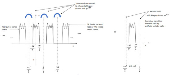
Rect is a rectangular function with a width W.
Then, we can develop a series of rectangle functions into a series of Fourier functions, which allows us to write: (see Figure 1 and [34])
we can note: as a wavenumber that leads to decompose
With
Equation (12) is proven based on the example (Example 3.17) of [39].
2.2. Modulation in Finite Almost-Periodic Arrays
As previously explained in [4,6], the interactions between cells in the spectral domain for periodic finite arrays are governed by a discrete phase law such that (with ), which comes from a rule-of-three math reasoning.
For a large period of finite arrays, ( is the hole interval of phases).
For a local period of finite arrays, (is the spectral contribution for one cell in position ) (p is the index position in a finite array, and d is the local period).
So, , where is the total number of elements in finite array, and p is the index position [13].
Figure 2 explains how to discretize the phases from the infinite case to the finite case. According to the same Figure 2, each cell interacts spectrally with its neighbors through the continuous Floquet modes (or the phase shift ) in the infinite case and (or the phase shift ) in the finite case.
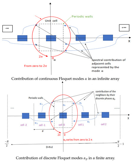
Figure 2.
Spectral representation of the interactions of a unit cell with its neighbors (infinite and finite cases) (valid for strong coupling interaction by using Floquet phases).
This allows writing the spectral solution as the sum of discrete Floquet states [4,33],
and
In the same way, with , and we can rewrite the spectral modulation law for a discrete Floquet mode [30],
Thus, the DFT is written as with and
from which
Eventually
3. MoM-GeC Modelization Based on Floquet Analysis
The problem formulation is already explained in [1,2,3,4,5,6,7]. It explains the development of the method of moments combined with Floquet spectral analysis to determine the electromagnetic performance in the presence of strong mutual couplings such as input impedance, surface current, surface electric field, radiated field, and directivity … etc.
4. Numerical Results
A part of our results was presented in [4,6,34,35]. Let us now display the other obtained results.
This approach can be applied to frequency-modulated continuous-wave (FMCW) radar antennas (to scan the radiation beam produced by very small areas of an antenna system) as well as to antennas that are massively placed in a coupled almost-periodic antenna array. The provided antenna example can be used to show how to model a 77 GHz (2 × 4) antenna array for frequency-modulated continuous-wave (FMCW) radar applications. The availability of antennas and antenna arrays in and on vehicles has become ordinary with the inclusion of remote crash-recognition-and-aversion systems, as well as lane-departure alerting systems. The two frequency bands appropriate for these systems are approximately 24 GHz and 77 GHz, respectively. In this model, we consider the microstrip patch antenna as a phased-array radiator. The dielectric substrate is air. According to Figure 3 and Figure 4, the patch antenna has its first resonance (parallel resonance) at 24.52 and 77.9 GHz (after adjusting the length of the used antenna). It is a common practice to shift this resonance to 24 and 77 GHz by scaling the length of the planar dipole antenna, as described in [35].
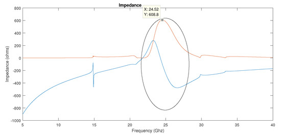
Figure 3.
Impedance variation against frequency band around 24 GHz: obtained by the MoM-GEC method.
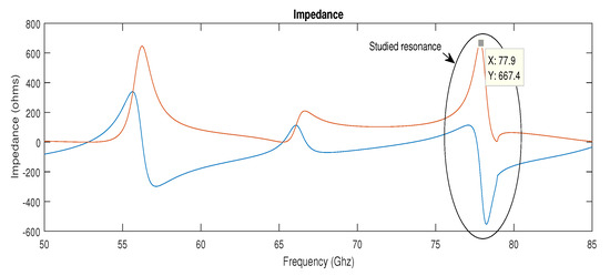
Figure 4.
Impedance variation against frequency band around 77 GHz: obtained by the MoM GEC method.
The next stage is to reconfirm the reflection coefficient of the planar antenna dipole, as depicted in Figure 5 and Figure 1 of [34]. The purpose of this check is to consider a good impedance match. It is very common to highlight the value as a limit value for the calculation of the bandwidth of the antenna. The deepest minima at 24 GHz and 77 GHz indicated a good fit with . The bandwidths of the antennas are roughly 1 GHz and 2 GHz, respectively. Thus, the spectrum bands are 23.5 GHz to 25.5 GHz and 76.5 GHz to 77.5 GHz. Finally, in terms of input impedances and S parameters, a good comparison between the adopted MoM GeC method and the references [41,42] is obtained.
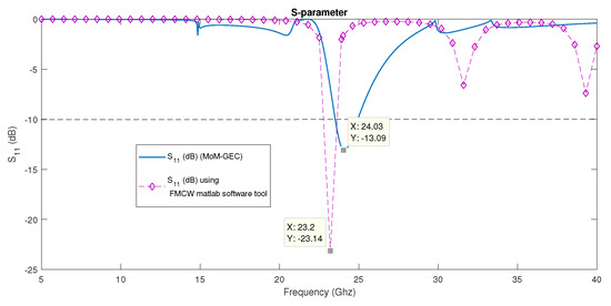
Figure 5.
-parameter (dB) variation against frequency band around 24 GHz: a comparison between the MoM-GEC and a MATLAB tool (see references [41,42]).
Therefore, the radiation pattern response for a small 2 × 4 antenna array is proposed based on the Floquet analysis (via the superposition theorem). Let us assume that the radar antenna system operates at 77 GHz with a bandwidth of 700 MHz. The following Figure 1 of [35] shows the spatial-radiation pattern of the resulting planar antenna using the superposition theorem of 2 × 4 Floquet radiation examples. Then, the sum of the discrete Floquet radiation patterns assigned to the FMCW radar permits the prediction of the global spatial-radiation pattern (what is called spatial modulation). A good comparison of the given numerical radiation pattern and the radiation obtained by patch array and cosine array is presented in Figure 3 of [35]. After validating the FMCW radar, we propose to evaluate the approach for a very large number of elements that uses the same frequency band at 24 and 77 GHz (for example, a lattice of 100 elements). Figure 6 gives an example of the superposition theorem (or a spatial modulation) for a large array to generate a spatial radiation pattern through the addition of the radiation patterns of Floquet states. After that, Figure 4 of [35] presents the variation of the spatial-radiation pattern (obtained using Floquet analysis) in the function of steering angles for 100 antenna elements that are distributed in a uni-dimensional configuration (for 5G application). In the same way, Figure 7 and Figure 5 of [35] show the variation of the 3D radiation pattern against different steering angles that are described with , and , in Cartesian coordinates and (u,v) space, respectively. Following the same study, Table 1 and Table 2 show the directivity values for each Floquet state and the superposition theorem (in the two cases of the FMCW radar and the 5G application), with two different steering angles and at the frequencies of 24 GHz and 77 GHz. From Figure 1 of [35] and Figure 6, we can see that the radiation patterns are nearly identical and verify the condition where the directivities are similar for both the Floquet states and the superposition theorem. This is why, in both Table 1 and Table 2, we find that all directivity values are identical (for the Floquet states as well as for the superposition), even when we change the steering angle. Knowing that generally, the directivity value close to 20 dB satisfies a narrow beam angle of about 20 degrees, as shown graphically in Figure 7a.
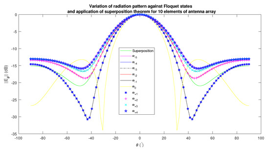
Figure 6.
Variation of radiation pattern against Floquet states and application of superposition theorem for 10 elements of antenna array (uni-dimentionnal configuration) at 77 GHz: obtained by the MoM-GEC method.
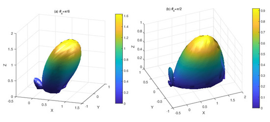
Figure 7.
Variation of radiation pattern against Floquet states and application of superposition theorem for 100 elements of antenna array (uni-dimentionnal configuration) at 77 GHz: obtained by the MoM-GEC method.

Table 1.
Directivity versus some Floquet states (considering 100 antenna arrays) and the superposition theorem (or the modulation as explained in Formula (13), which transformed to study a finite array) for steering angles (used for 5G application).
Table 2.
Directivity versus Floquet states and the superposition theorem (or the modulation as explained in Formula (13), which transformed to study a finite array) for steering angles (FMCW radar application).
5. Conclusions
In this article, we illustrated the principle of Floquet spectral modulation based on the Fourier analysis (and its spatial form) to study almost-periodic sub-arrays (with finite size) in the presence of strong mutual coupling interaction, defined on infinite support (or a really large finite size). This study is very useful for the new generation of technologies based on millimeter and terahertz waves in phased arrays, for example, in dense-massive-MIMO, smart-surfaces, 5G, and 6G applications. In future work, we are interested to investigate the randomly modulated almost-periodic arrays (also in the presence of strong coupling).
Author Contributions
Conceptualization, H.B.; software, H.B. and A.T.; formal analysis, H.B. and A.T.; investigation, H.B. and A.T.; writing—original draft preparation, H.B. and A.T.; writing—review and editing, H.B. and A.T. All authors have read and agreed to the published version of the manuscript.
Funding
This project received funding from the Laboratory Sys’Com-ENIT (LR-99- ES21)-National Engineering School of Tunis ENIT, Tunis, Tunisia, 1002.
Data Availability Statement
Not applicable.
Acknowledgments
I would like to thank each of the Ammar Bouallegue (ENIT Tunis-El Manar University), Christophe Craeye (UCLouvain University), Junwu TAO (N7-University of Toulouse) and especiallyHenri Baudrand (N7-University of Toulouse), who died recently, for their help in the achievement of this work.
Conflicts of Interest
The authors declare no conflict of interest.
References
- Mekkioui, Z.; Baudrand, H. Bi-Periodic Centered-Fed Microstrip Leaky-Wave Antenna (LWA) Analysis by a Source Modal Decomposition in Spectral Domain; IET Microwaves Antennas and Propagation: Sarrebruck, Germany, 2009; pp. 1141–1149. [Google Scholar]
- Baudrand, H.; Titaouine, M.; Raveu, N.; Fontgland, G. Electromagnetic modeling of planar almost periodic structures. In Proceedings of the SBMOI/IEEE MTT-S International Microwave and Optoelectronics Conference, Belem, Brazil, 3–6 November 2009; pp. 427–431. [Google Scholar]
- Azizi, M.K.; Latrach, L.; Raveu, N.; Gharsallah, A.; Baudrand, H. A new approach of almost periodic lumped elements circuits by an iterative method using auxiliary sources. Am. Appl. Sci. 2013, 10, 1457–1472. [Google Scholar] [CrossRef]
- Hamdi, B.; Aguili, T.; Raveu, N.; Baudrand, H. Calculation of the mutual coupling parameters and their effects in 1-D planar almost periodic structures. Prog. Electromagn. Res. 2014, 59, 269–289. [Google Scholar] [CrossRef]
- Hamdi, B.; Aguili, T.; Tao, J. Modélisation des Circuits Presque-Périodiques; Éditions Universitaires Européennes: Sarrebruck, Germany, 2019; 156p, ISBN 6138476387, ISBN 978-6138476382. [Google Scholar]
- Hamdi, B.; Aguili, T.; Baudrand, H. Floquet Modal Analysis To Modelize and Study 2-D Planar Almost Periodic Structures In Finite And Infinite Extent With Coupled Motifs. Prog. Electromagn. Res. B 2015, 62, 63–86. [Google Scholar] [CrossRef]
- Latifa, N.B.; Aguili, T. Synthesis and Optimization of Almost Periodic Antennas Using Floquet Modal Analysis and MoM-GEC Method. J. Electromagn. Anal. Appl. 2019, 11, 1–16. [Google Scholar] [CrossRef]
- Ishimaru, A.; Coe, R.J.; Miller, G.E.; Green, W.P. Finite periodic structure approach to large scanning array problems. IEEE Trans. Antennas Propagat. 1985, 33, 1213–1220. [Google Scholar] [CrossRef]
- Valerio, G.; Baccarelli, P.; Burghignoli, P.; Galli, A.; Rodrguez-Berral, R.; Mesa, F. Analysis of periodic shielded microstrip lines excited by nonperiodic sources through the array scanning method. Radio Sci. 2008, 43, 1–15. [Google Scholar] [CrossRef]
- Rodrguez-Berral, R.; Mesa, F.; Baccarelli, P.; Burghignoli, P. Excitation of a periodic microstrip line by an aperiodic delta-gap source. IEEE Trans. Antennas Propagat. Lett. 2009, 8, 641–644. [Google Scholar] [CrossRef]
- Dardenne, X.; Craeye, C. Application of the Array Scanning Method with Windowing to the Analysis of Finite Rectangular Periodic Structures. In Proceedings of the 2005 18th International Conference on Applied Electromagnetics and Communications, Dubrovnik, Croatia, 12–14 October 2005; pp. 1–4. [Google Scholar] [CrossRef]
- Craeye, C.; González-Ovejero, D. A review on array mutual coupling analysis. Radio Sci. 2012, 46, 1–25. [Google Scholar] [CrossRef]
- Craeye, C. Expoitation of Infinte-Array Results for Accurate Solution of Finite Widebands Arrays. In Proceedings of the URSI Electromagnetic Theory Symposium (EMTS’07), San Diego, CA, USA, 27–31 May 2019. [Google Scholar]
- Mesa, F.; di Nallo, C.; Jackson, D.R. The theory of surface-wave and space-wave leaky-mode excitation on microstrip lines. IEEE Trans. Microw. Theory Tech. 1999, 47, 207–215. [Google Scholar] [CrossRef]
- Capolino, F. Theory and Phenomena of Metamaterials; CRC Press: Boca Raton, FL, USA, 2017. [Google Scholar]
- Skrivervik, K.; Mosig, L.R. Finite phased array of microstrip patch antennas: The infinite array approach. IEEE Trans. Antennas Propagat. 1992, 40, 579–582. [Google Scholar] [CrossRef]
- Skrivervik, K.; Mosig, J.R. Réseaux Périodiques D’antennes Microruban; Thèse n° 1032; EPFL: Lausanne, Switzerland, 1992. [Google Scholar]
- Sze, K.Y.; Shafai, L. Reflection properties of infinite periodic arrays of rectangular conducting patches. Can. J. Electr. Comput.-Eng.-Rev. Can. Genie Electr. Inform. 1999, 24, 27–33. [Google Scholar]
- Vardaxoglou, J.C. Frequency Selective Surfaces, Analysis and Design; John Wiley and Sons: Hoboken, NJ, USA, 1997. [Google Scholar]
- De Sabata, A.; Matekovits, L.; Lipan, O. Band pattern of commensurate modulated periodic structures. IET Microw. Antennas Propag. 2017, 11, 1303–1307. [Google Scholar] [CrossRef]
- Salazar-Arrieta, J.d.J.; Halevi, P. Wave Propagation in Electric Periodic Structure in Space with Modulation in Time (2D+ 1). I. Theory. arXiv 2021, arXiv:2105.07105. [Google Scholar]
- Patel, A.M.; Grbic, A. A Printed Leaky-Wave Antenna Based on a Sinusoidally-Modulated Reactance Surface. IEEE Trans. Antennas Propag. 2011, 59, 2087–2096. [Google Scholar] [CrossRef]
- Oliner, A.; Hessel, A. Guided waves on sinusoidally-modulated reactance surfaces. IRE Trans. Antennas Propag. 1959, 7, 201–208. [Google Scholar] [CrossRef]
- Watanabe, K. Study on Spectral-Domain Formulation of Electromagnetic Scattering by Periodic Strip Array with Period Modulation. In Proceedings of the 2019 IEEE Conference on Antenna Measurements & Applications (CAMA), Kuta, Indonesia, 1 October 2019; pp. 165–166. [Google Scholar] [CrossRef]
- Watanabe, K. Spectral-domain approach to electromagnetic scattering from imperfectly periodic structures. In Proceedings of the 2010 International Conference on Mathematical Methods in Electromagnetic Theory, Kyiv, Ukraine, 6–8 September 2010; pp. 1–6. [Google Scholar]
- Watanabe, K.; Yasumoto, K. Two-dimensional electromagnetic scattering of non-plane incident waves by periodic structures. Prog. Electromagn. Res. 2007, 74, 241–271. [Google Scholar] [CrossRef][Green Version]
- Bhattacharyya, A.K. Phased Array Antennas: Floquet Analysis, Synthesis, BFNs and Active Array Systems; John Wiley & Sons: Hoboken, NJ, USA, 2006. [Google Scholar]
- Abdallah, Y.; Menudier, C.; Thevenot, M.; Monediere, T. Investigations of the effects of mutual coupling in reflectarray antennas. IEEE Antennas Propag. Mag. 2013, 55, 49–61. [Google Scholar] [CrossRef]
- Appendix B: Almost-Periodic Functions and Their Spectra. 2009. Available online: https://rd.springer.com/content/pdf/bbm:978-1-84882-181-1%2F1.pdf (accessed on 20 November 2021).
- Berger, N.K. Spectral measurements with superresolution based on periodic modulation of the spectrum. Appl. Opt. 2008, 47, 6535–6542. [Google Scholar] [CrossRef]
- Berger, N.K. Periodic modulation-based spectral and temporal superresolution with a single measurement. Appl. Opt. 2015, 54, 2999–3009. [Google Scholar]
- Janos, W. Optimal filtering of periodic pulse-modulated time series. IRE Trans. Inf. Theory 1959, 5, 67–74. [Google Scholar] [CrossRef]
- Pollastri, A. Periodic Structures EE625 Periodic Structures and Floquet’s Theorem Periodic Structures. Available online: https://www.academia.edu/13976543/Periodic_Structures_and_Floquets_Theorem (accessed on 20 November 2021).
- Hamdi, B.; Aguili, T. Spectral Floquet analysis devoted to meta-surface applied for 5G and planned 6G antenna designs. In Proceedings of the 2021 IEEE 19th International Symposium on Antenna Technology and Applied Electromagnetics (ANTEM), Winnipeg, MB, Canada, 8–11 August 2021; pp. 1–2. [Google Scholar] [CrossRef]
- Hamdi, B.; Aguili, T. MoM-GEC combined with Floquet analysis to study scanned coupled almost periodic antenna arrays in massive MIMO for 5G generation and FMCW automotive radar applications. In Proceedings of the 2020 IEEE International Symposium on Antennas and Propagation and North American Radio Science Meeting, Montréal, QC, Canada, 5–10 July 2020; pp. 1941–1942. [Google Scholar] [CrossRef]
- Mekkioui, Z.; Baudrand, H. A full-wave analysis of uniform microstrip leaky-wave antenna with arbitrary metallic strips. Electromagnetics 2008, 28, 296–314. [Google Scholar] [CrossRef]
- Smith, O.J. Mathematics of the Discrete Fourier Transform (DFT) with Audio Applications. 2007. Available online: https://ccrma.stanford.edu/jos/st/Sampling_Theorem.html (accessed on 20 November 2021).
- Peacock, J.A. School of Physics and Astronomy-Fourier Analysis. Available online: https://www.roe.ac.uk/japwww/teaching/fourier/fourier_lectures_part1.pdf (accessed on 20 November 2021).
- Grami, A. Introduction to Digital Communications; Elseveir: Amsterdam, The Netherlands, 2015. [Google Scholar]
- González-Velasco, E.A. Fourier Analysis and Boundary Value Problems; Elseveir: Amsterdam, The Netherlands, 1995. [Google Scholar]
- Patch Antenna Array for FMCW Radar—MATLAB and Simulink. 2019. Available online: https://fr.mathworks.com/help/phased/ug/patch-antenna-array-for-fmcw-radar.html (accessed on 20 November 2021).
- Kulke, R.; Günner, C.; Holzwarth, S.; Kassner, J.; Lauer, A.; Rittweger, M.; Uhlig, P.; Weig, P. 24 GHz Radar Sensor integrates Patch Antenna and Frontend Module in single Multilayer LTCC Substrate. In Proceedings of the European Microelectronics and Packaging Conference, Brugge, Belgium, 12–15 June 2005. [Google Scholar]


Publisher’s Note: MDPI stays neutral with regard to jurisdictional claims in published maps and institutional affiliations. |
© 2021 by the authors. Licensee MDPI, Basel, Switzerland. This article is an open access article distributed under the terms and conditions of the Creative Commons Attribution (CC BY) license (https://creativecommons.org/licenses/by/4.0/).