Article

A Precise Current Detection Method Using a Single Shunt and FET Rds(on) of a Low-Voltage Three-Phase Inverter

Electric Motor Control Laboratory, Graduate School of Automotive Engineering, Kookmin University, Seoul 02707, Korea
*
Author to whom correspondence should be addressed.
Electronics 2022, 11(1), 9; https://doi.org/10.3390/electronics11010009
Submission received: 9 November 2021 / Revised: 10 December 2021 / Accepted: 20 December 2021 / Published: 22 December 2021

Abstract

:
In this study, a low-voltage three-phase inverter was used alongside a shunt resistor to measure the current. However, it is known that this type of inverter and shunt resistor system has a region where the measurement of current is impossible due to structural limitations. As a result, many studies have focused on this region through the use of additional algorithms. Most studies measured current by forcibly adjusting the PWM duty in order to measure the current at the region where it could not be sensed. However, unfortunately, the total harmonic distortion (THD) increases in the current due to PWM adjustment. This causes an increase in torque ripple and inverter control instability. Therefore, in this paper, current was measured using the Rds(on) value between the drain source resistor when MOSFET was turned on and the Kalman filter in a low-voltage three-phase inverter with a single shunt. Additionally, the value was verified via comparison with the values achieved when a Hall-type current sensor and single shunt were used. As a result, this study confirmed that the inverter with a single shunt performs the same as a Hall-type sensor at the region where current cannot be detected.

1. Introduction

AC devices are widely used in various energy conversion fields. In particular, the field of application for inverters that use three-phase voltage sources has gradually expanded and provides opportunities for energy efficiency improvement in various industries. The main application areas of three-phase voltage source inverters are those such as motor control in digital appliances and industry. A considerable amount of research has yielded valuable results, and many high-performance technologies such as non-linear, adaptive, optimal, and intelligent control have been applied to AC drives. Among many technologies, research on current measurement is receiving a lot of attention. According to a recent study, a virtual inductor circuit is proposed to reduce the circuit complexity in sensing inductance current [1] or a method of adaptively changing the transient response and voltage scaling rate with time by limiting the time of the switch to the equivalent duty cycle due to the minimum off-time and fixed on-time, [2] the use of a hysteresis current control buck converter using constant frequency and active current sensing technology [3], and the valley current mode using adaptive on time(AOT) [4].
However, among those methods, Hall-type current sensors are widely used. A lot of research on single current sensors has been done recently. Low-speed sensorless control of permanent magnet synchronous machines with a single current sensor [5], maximum efficiency control using a single current sensor that minimizes core and copper losses online [6], and a single current sensor based on the principle of superposition. Research on current control techniques using a single current sensor, such as a specific overmodulation control method [7], is being actively conducted. Additionally, research on judgment and control strategies in case of sensor failure is mainly focused. A simple, non-intrusive method to identify and correct measurement errors using a single current sensor in a current short-circuit situation [8], a viable internal permanent magnet synchronous motor drive that realizes the purpose of reconstructing the current in the event of a single current sensor failure. Ref. [9], a study on the reduction of current error for a motor drive of an inverter using a 3-phase 4 switch and a single current sensor [10], and fault diagnosis of a position sensor and a current sensor [11,12], etc. Contactless current sensors such as Hall-type current sensors are composed of integrated circuits, so EMI countermeasures against radio frequency are required (Refs. [13,14,15,16,17]). In addition, as well as Hall-type current sensors, research using a current transformer (CT) or shunt to measure current accurately at low cost is one example of design [18,19,20,21,22].
In those, single-shunt resistor inverters and three-shunt resistor inverters are cost-effective, but there are areas that cannot be measured without additional technology. In addition, most techniques for use in current measurement are based on a signal injection at the carrier frequency, resulting in additional torque ripple and audible noise. These drawbacks mean that the existing method of reconstructing the phase current from the current signal measured in the circuit must be examined by using an additional algorithm. Regarding these applications, the method of injecting a voltage signal with a low minimum amplitude or audible frequency enables one to reconstruct the phase current of the PWM inverter. It guarantees the measurement time required to reconstruct the phase current. Then, the required minimum-distance voltage vector is injected. Injection sequence control is also required to avoid sudden changes in the injection signal [23,24]. A PWM method that divides the phase voltage to reduce audible noise in low-speed operations exists. The methods proposed above reconstruct the phase current using the signal of a single-current sensor and minimize the amplitude of the injected signal to reduce harmonics in the audible noise frequency of the injected signal (Refs. [25,26]). However, in the above methods, an undetectable current exists in each current. The method proposed in this paper measures the undetectable region of a current using a shunt resistor and MOSFET Rds(on) for the single-shunt resistor inverter system and proposes a method to enable one to achieve the more accurate estimation of the Rds(on) resistance value by designing a Kalman filter. As a result of the test, the proposed method was compared with a Hall-type current sensor and single shunt, and the effectiveness and validity of the algorithm were verified.

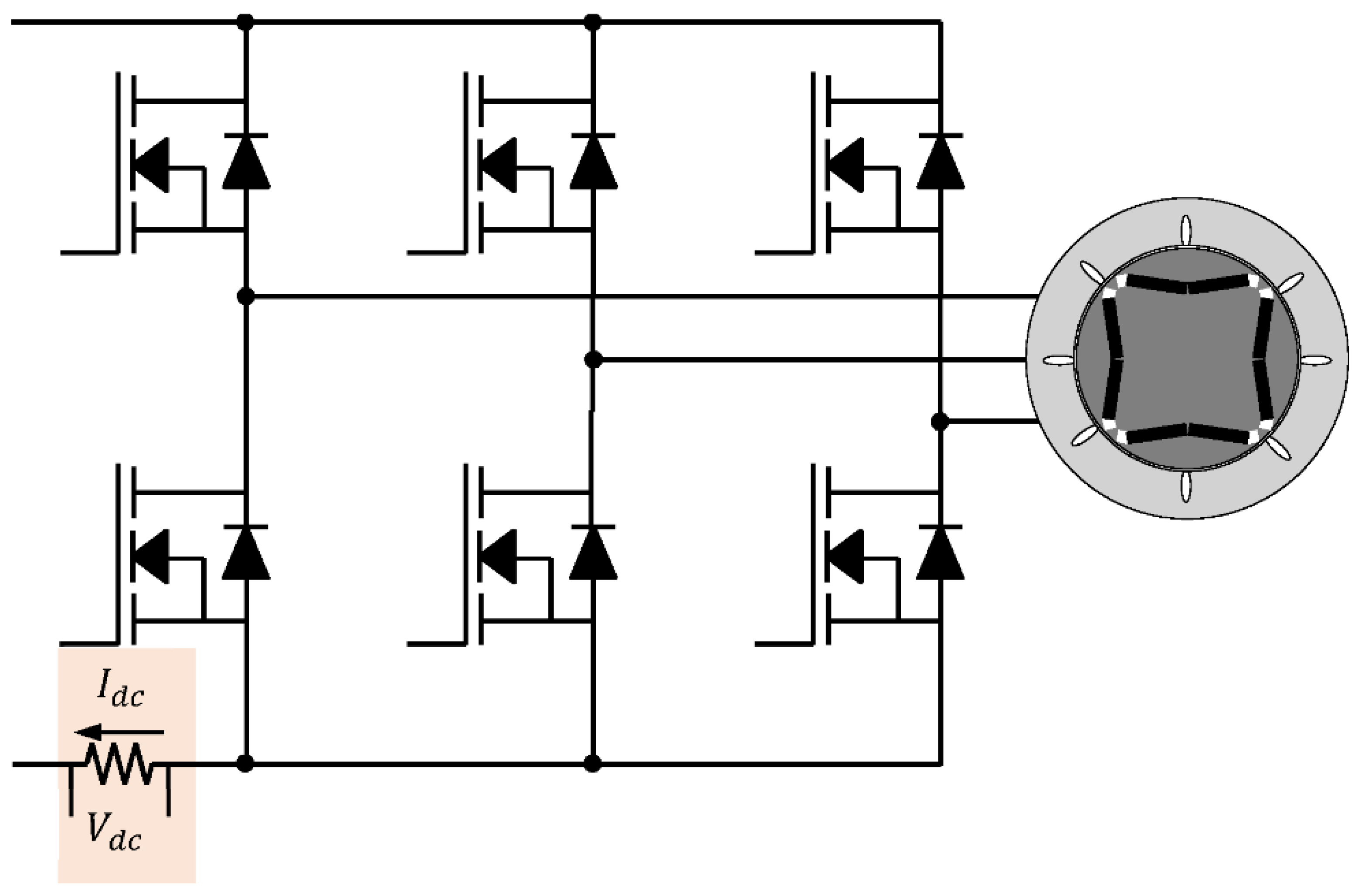
2. Current Detection Method Using Single-Shunt Resistor and MOSFET Rds(on) in Low-Voltage Three-Phase Inverter

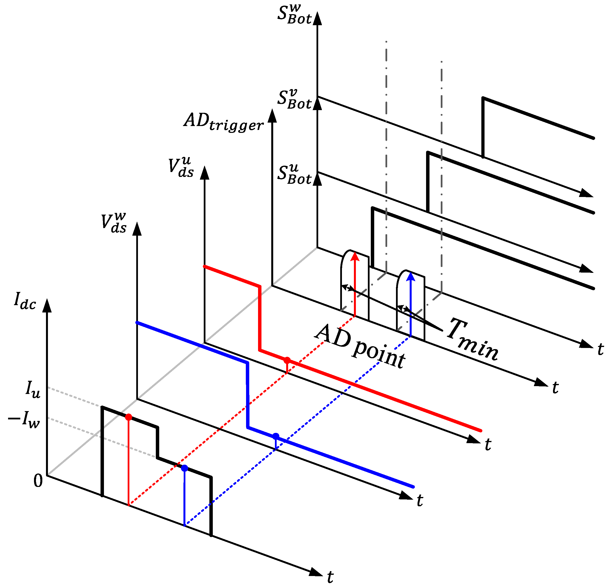
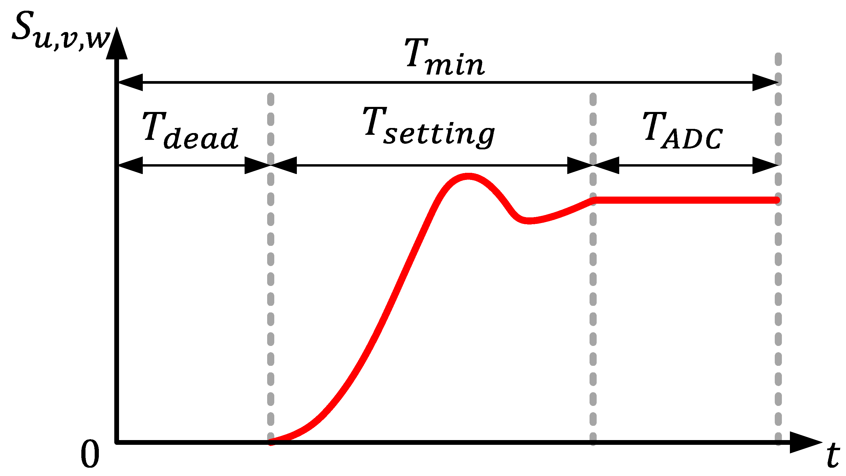
2.1. Current Detection Method Using the Existing Single Shunt Resistor

The voltage between drain and source can be measured when the MOSFET is on. Figure 1 shows the ADC (analog digital converter) point when the bottom switch is on in a single-shunt inverter system.
The result of this configuration is that the current flows through the Rds(on) resistor, as shown in the figure. If the current flowing through the single shunt measured through the ADC point and the voltage applied to the bottom of the MOSFET are measured, Rds(on) can be calculated as follows through Ohm’s law.
As presented in Figure 1, the AD trigger is used simultaneously to when the effective vector is applied. When the current is detected using this technique, it appears as shown in Figure 2 As shown in Figure 3, a single-shunt resistor inverter is a system configuration that measures a current using one shunt resistor.
The shunt resistor is located at the negative point of the DC link, as shown in Figure 3, and can be used for current control by detecting each phase current according to the PWM application sequence of U, V, and W phases. This method is economical because the circuit configuration is relatively simple, and it is possible to use not only the linear output region, but also the overmodulation output region. However, as shown in Figure 1, the ADC requires a minimum time (Tmin) in order to detect current. If the effective vector time is longer than this time, the current cannot be detected by a single-shunt resistor inverter system. Such a region is called an undetectable current region. In this area, two or more output voltages are defined as similar sections. This area is divided into two areas, as shown in Figure 4. The undetectable area is divided into two areas: a band area and a star area. Basically, when measuring current using a single shunt in a two-level low-voltage inverter structure, it is measured at the dc link negative stage using three FETs at the bottom among six FETs. Current sampling is performed twice per PWM cycle. As shown in Figure 1 for each sampling, current sampling is possible twice per PWM cycle. However, if the two-phase PWM command size is similar or the three-phase PWM size is similar, the time to AD current becomes insufficient and accurate sampling is physically impossible. Among them, if the PWM command size of two phases is similar, the time to AD of the current of one phase becomes insufficient, and the current detection becomes impossible. As shown in the upper figure in Figure 4b, the PWM form comes out and it appears like the gray area in Figure 4a, which is usually called a band area. If the PWM commands of three phases are similar as shown in the figure below in Figure 4b, the time to AD of the current of two phases is insufficient, creating a region where current detection is impossible. At this time, it appears as a star-shaped area as shown in Figure 4a. This area is called a star area.
The six sections shown as bands in Figure 4a are the corresponding parts of Figure 4b in the top picture. Current detection is possible in the T1 region, but current detection is impossible in the T2 region because the minimum time needed to detect the current is not available. In this area, only the phase current can be detected. The section shown as a star in Figure 4a corresponds to Figure 4b in the bottom picture. In both T1 and T2, the minimum time needed to detect the current is not available. In these sections, current detection is impossible.
As described above, the main reason that an area exists where current cannot be detected in a single-shunt resistor inverter is the lack of the minimum time needed for current detection, as shown in Figure 5. This is called Tmin, and the configuration is as follows:
T m i n = T d e a d + T s e t t i n g + T a d c
Tdead is the dead time, Tsetting is the PWM ON steady-state arrival time, and Tadc is the ADC operation time. A limitation is that the time taken to detect the current in the single-shunt resistor inverter should be longer than the Tmin defined in Equation (1). If the Tmin is not secured, it is impossible to detect the current with the shunt resistor. Equation (1) varies depending on the experimental situation or MCU type and setting, but the Tmin time is usually about 2~3 us. It takes about Tdead (1~2 us), Tsetting (300~600 ns), and Tadc (200~400 ns).

2.2. Current Measurement Method Using MOSFET Rds(on)

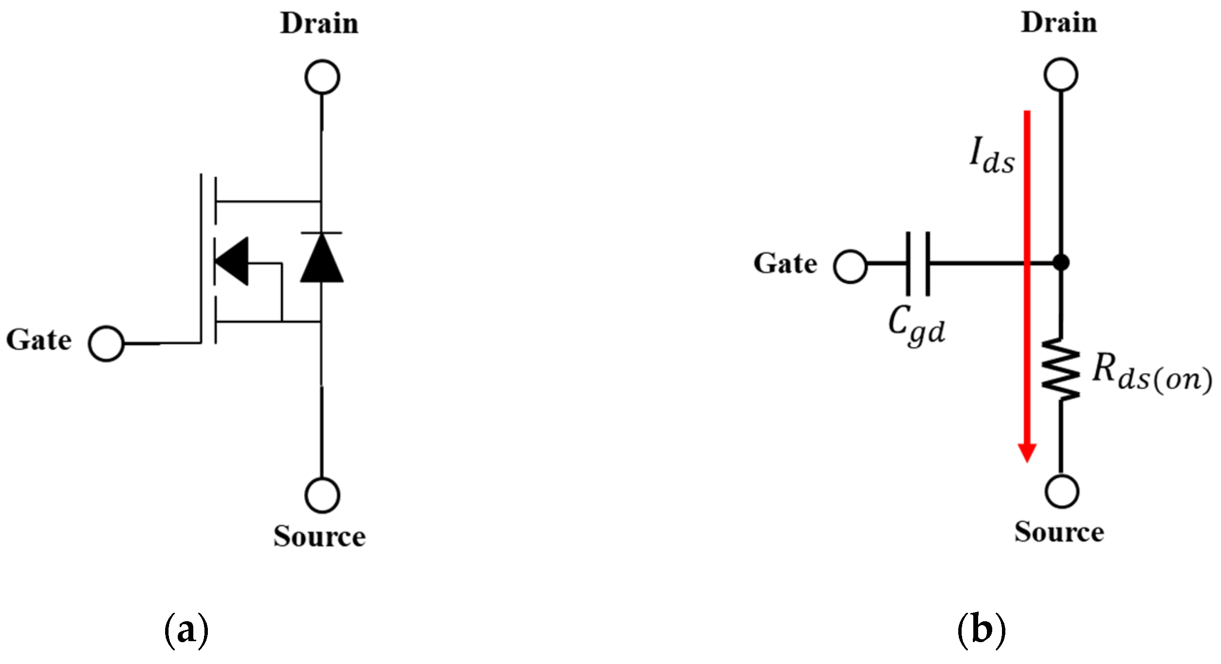
2.2.1. Basic Operating Characteristics of MOSFET Rds(on)

In general, MOSFETs used in low-voltage inverters can be configured as shown in Figure 6a. When the gate signal of the MOSFET is turned on, as shown in Figure 6b, and a positive voltage signal is injected from the gate, the hole existing under the oxide layer is pushed under the substrate, and the depletion region is filled with combined negative charges. At this time, current flows between the drain and source. Simultaneous to when the flow of current occurs, a resistive action is found between the drain sources. This continuity resistance is called Rds(on) resistance.
This resistor has a larger resistance than the shunt resistor usually used in low-voltage inverters. If the voltage between the drain and source of MOSFET and Rds(on) of MOSFET are detected in accordance with Equation (2), the current can be obtained through calculation, and more effective current detection compared to the detection of current using a shunt resistor may be possible (Refs. [27,28,29]). However, when Rds(on) is calculated by simple measurement during actual measurement, a current error of 10% or more may occur due to noise components. In addition, when MOSFETs are used for current measurement, additional mathematical modeling or additional circuits are required because they are vulnerable to EMI or EMC and difficult to measure (Refs. [17,30]). In this paper, a Kalman filter is designed to more accurately estimate Rds(on).
I d s = V D S ( o n ) R D S ( o n )

2.2.2. Correction of MOSFET Rds(on) Using Kalman Filter

The estimated MOSFET Rds(on) value can be calculated in theory, but it is difficult to accurately calculate Rds(on) for practical use due to measurement noise (Refs. [31,32,33,34]). Therefore, in this paper, we attempted to improve the accuracy of the estimation of Rds(on) of MOSFET by using a Kalman filter. It uses a simple 1D formula. The measurement process was modeled as follows:
{ x K + 1 = A x k + w k z k = H x k + u k  
where xk is the kth measurement, wk is the noise of the Gaussian model and has a variance of Q, uk follows Gaussian distribution and means measurement noise, A and H are scalar quantities equal to 1, and the variance of the estimation error is P. The order of estimation error, Kalman gain calculation, estimation value calculation, and error covariance calculation are each denoted as follows:
P k + 1 | k = P k | k + Q  
K k + 1 = P k + 1 | k P k + 1 | k + R
x ^ k + 1 | k + 1 = x ^ k + 1 | k + K k + 1 ( z k + 1 x ^ k + 1 | k )  
P k + 1 | k + 1 = P k + 1 ( 1 K k + 1 )  
In this paper, the extended Kalman filter was applied, and the basic algorithm of the extended Kalman filter was the same as the Kalman filter except for the linearization of the mean and covariance.

2.2.3. MOSFET Junction Temperature Estimation

It is generally known that Rds(on) is not constant. In order to accurately determine Rds(on), it is necessary to evaluate the dependence on the junction temperature, Tj. In the MOSFET MTI145WX100GD data sheet [32] that was selected in this paper, there is a graph of Rds(on) as a function of temperature. This is shown in Figure 7, and points marked with * are extracted from the curve and summarized in Table 1, where Rds(on) nom represents the normalized MOSFET resistance.
R d s ( o n ) _ n o m = R d s ( o n ) ( T j ) R d s ( o n ) ( 25   ° C )
R d s ( o n ) _ n o m = K 0 T j 2 + K 1 T j + K 2
Here, K0, K1, and K2 are shown in Table 2. As can be seen above, the evaluation of the junction temperature is an important aspect that enables one to estimate the correct Rds(on). Refs. [33,34] The junction temperature was estimated using the Rds(on) value defined through the above analysis and Equation (9). In addition, a temperature saturation experiment was performed using a GL240 data logger, a product of KOSTECH, and the validity and utility of the estimation were verified through this.

3. Experiment Using Rds(on) of MOSFET in Single Shunt Inverter System

3.1. Rds(on) Initial Value of MOSFET

Figure 8 shows a 12 V 500 W inverter using MOSFET MTI145WX100GD to estimate Rds(on). Considering the case where Tmin was not secured for initial resistance detection as described above, Rds(on) was calculated by securing a time longer than Tmin using the minimum voltage injection method. It can be seen that the Rds(on) was estimated using the setup displayed in the figure below. At this time, initial resistance was selected by averaging the resistance when the steady state was reached.
To select the initial value, proceed as follows in Figure 9:
Calculate the ADC initial value of the single-shunt resistor. In order to minimize the error due to measurement, ADC offset is calculated as the average of 16,000 samples;
Move the PWM of one phase to secure the Tmin (2~3 us), measure Vds, and measure the current flowing through the shunt resistor at the same time;
Move the PWM of the other phase to secure the time of Tmin (2~3 us), measure Vds, and measure the current flowing through the shunt resistor at the same time.
The initial value was measured in the same way as above, as shown in Figure 10; it was measured by being sampled 1000 times in 0.1 s. The initial value of Rds(on) at 25 °C of the MOSFET (MTI145WX100GD) was determined to be 1.7 mΩ.

3.1.1. Rds(on) of MOSFET Using Kalman filter

In this paper, the accuracy of the estimation of Rds(on) was improved by designing a Kalman filter. The state equation and measurement equation of the measured Rds(on) were the same as those shown in Equation (3). Since the measurement of Rds(on) was directly measured rather than expressed as an expression through a differential equation for the measured value, matrix A and matrix H could be defined as identity matrices. In principle, matrix Q and matrix R should be constructed by accurately reflecting the characteristics of noise, but there is a limit to their analytical determination because various errors are compounded (Ref. [31]). Therefore, in this paper, matrix Q and matrix R values were selected through experimental analysis. The results according to the experiment are shown in Figure 10. In this paper, the optimal value was selected and experimentally corrected. Additionally, the initial Rds(on) was based on the data sheet value (1.7 mΩ).
As a result of detection using a Kalman filter, the result shown in Figure 9 was obtained. It can be seen that there is a clear difference in the amount of dispersion that can be visually confirmed. As a result of using a Kalman filter, when the Q value was 0.1 and the R value was 2, the error was the smallest. It was confirmed that the maximum error of the initial value was 0.4% and the average of the error was 0.23%.

3.1.2. Estimation of Rds(on) According to Rds(on) Temperature Change

The Rds(on) of MOSFET, as described above (Rds(on) is shown in Figure 7), changes with temperature. Although the value of Rds(on) changes with respect to the drain source voltage and drain current, compared to the change with temperature, this change is negligible, so only the change in regards to temperature is considered in this paper.
Regarding temperature, the Rds(on) varies from MOSFET to MOSFET, but the data sheet of the MTI145WX100GD that was used here is shown in Figure 7. In order to compare and confirm the data sheet in Table 1 above and the algorithm presented in this paper, the following experimental environment was prepared. Experiments were conducted at 25, 50, and 75 °C. In the temperature measurement method, the measurement of direct junction temperature is not possible due to the packaging of the MOSFET, so the current that saturates each temperature is experimentally found so that the temperature can be sufficiently saturated using a TC surface of the MOSFET.
The data logger used, shown in Figure 11, was a GL240, a product of KOSTECH, which enables ten channels and a device that can store data such as voltage, current, and temperature to be logged. In addition, the temperature saturation time was assumed to be 30 min, and the sampling rate was set to 500 ms. The results shown in Figure 11 are summarized in Table 3. The actual temperature shown in the results was measured based on the highest temperature among the three TCs.
The average Rds(on) in Table 3 was determined based on the lower end of the u-phase FET. As for the values of the data sheet, Figure 11a–c were selected based on the measured temperature of the MOSFET of 25, 50, and 75 °C.

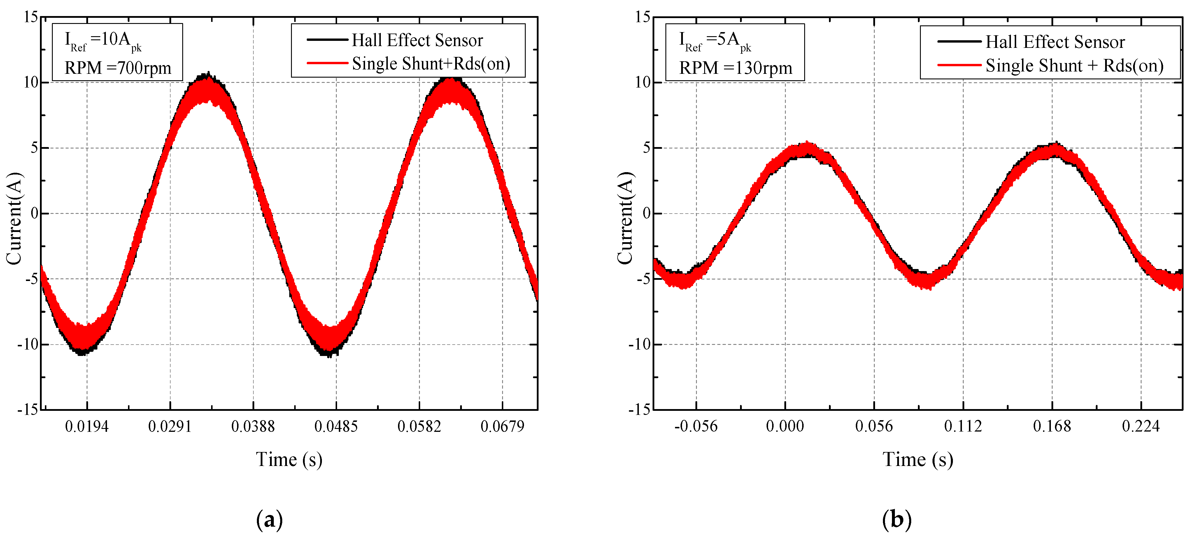
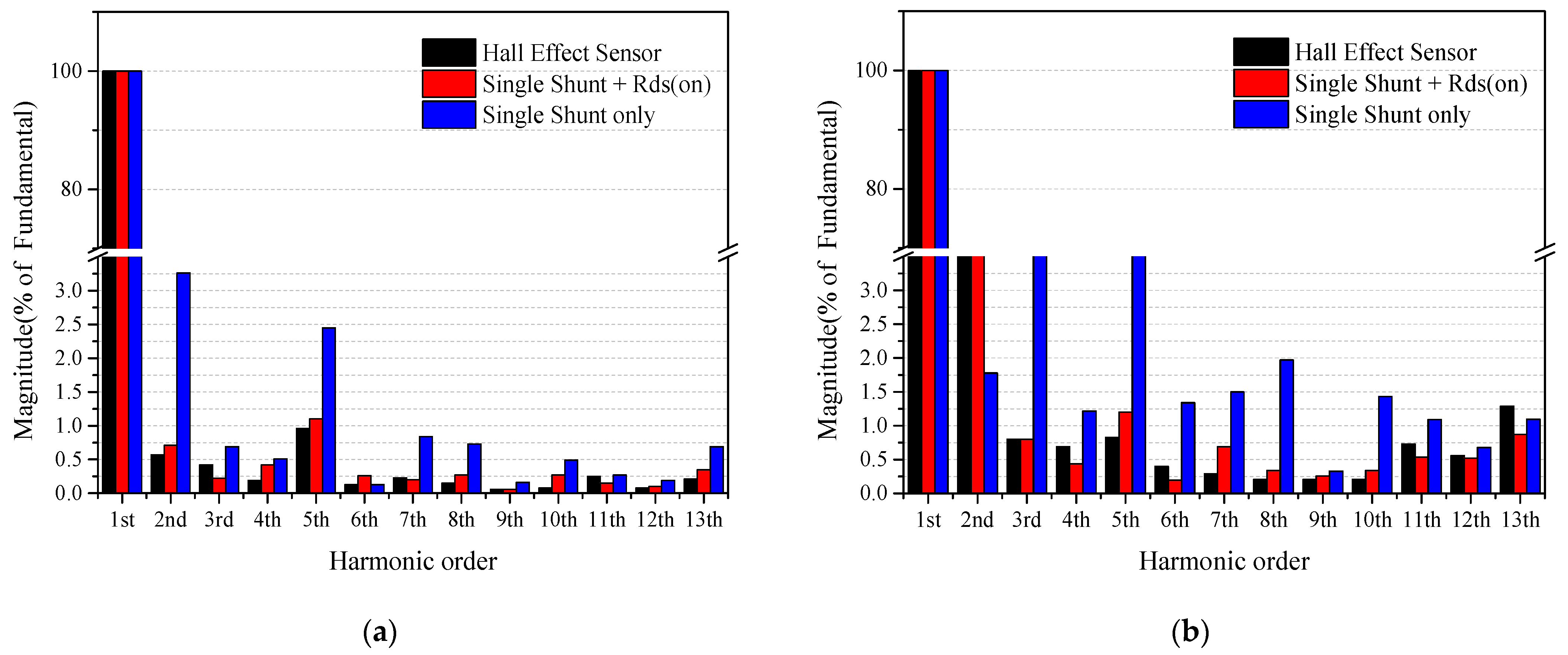
3.2. Current Measurement Using Rds(on) of MOSFET

The following section describes the measurement results obtained while the motor was controlled. The results for the current non-detection region, shown in Figure 4, were compared with the algorithm presented in this paper (the method using a single shunt and Rds(on)) for each relevant area and when the motor current was controlled by the current sensor. Figure 12a shows the current control in the band area. Figure 12b shows the current control in the star region. In Figure 12, it is shown that in both scenarios, Rds(on) values changed as the temperature rose. It is also confirmed that the rms value of the current with respect to the temperature change was maintained. In addition, as shown in Figure 12, the Hall-effect current sensor was compared, and the THD and frequency analyses were also conducted.
Allegro’s ACS-758KCB-150B-PSS-T was used as the current sensor. The operation area in Figure 13a is the area (band) in Figure 4b. Experimental results at 700 rpm and 10 Apk are displayed. The operation area in Figure 13b is the area (star) in Figure 4b. These are the experimental results at 5 Apk at 130 rpm. THD was analyzed by organizing the experimental waveforms. Each total harmonic distortion (THD) is summarized in Table 4.
As shown in Table 4, when the Hall-effect sensor was used, the THD was 2.37 and 1.73%, respectively, in the current undetectable area in the system using a single shunt. It was confirmed that the THD using the Rds(on) of MOSFET with a single shunt, the method presented in this paper, showed similar performance to the current sensor in each area. In addition, the THD was lowered by 1.3% in situation (a) (band area) and 2.75% in situation (b) (star area) than the method that only used a single shunt.
As can be seen in Figure 14, the frequency analysis in the band area showed that the influence of harmonics was reduced for the entire area, but in particular, it was confirmed that the influence of harmonics was more significantly reduced in the second and fifth orders than in single shunt alone, and a similar phenomenon was shown for the performance of the Hall-effect current sensor. Similarly, in the star area, it can be confirmed that all the areas except for the second harmonic were reduced compared to when a single shunt was used, and in particular, the third and fifth harmonics were reduced. Performance comparisons with converters studied to date are listed in Table 5.

4. Conclusions and Further Work

In this paper, the resistance of the source between drains was measured when the MOSFET was switched on in a low-voltage inverter system using a single shunt, and the accuracy of the measurement was improved by using a Kalman filter. Additionally, an OP-AMP circuit that could measure the drain source voltage of the switch at the bottom of the MOSFET was tested, but it did not add much loss, so it did not have a big impact on the unit cost. The OP-AMP used in this study is ON Semiconductor’s MC33202VDR2G, which is a two-channel OP-AMP and is a device widely used in current research. Based on Mouser (electronic component distribution company), as of 21.11.25 days, when purchasing reel units, it is $0.278 each. As it is a 2-channel OP-AMP, it is used by measuring the voltage of the lower switch of v-phase and w-phase with one component. Through the obtained results, it was confirmed that the MOSFET can be used to measure and control current. In particular, it was confirmed that a more accurate MOSFET Rds(on) can be approximated through the temperature equation by considering the temperature dependence of the MOSFET Rds(on). A motor can be effectively used in the single-shunt system, which is a low-voltage inverter, such as electronic power steering system. In addition, through experiments, it was confirmed that the current can be controlled as much as the accuracy of the current sensor.

Author Contributions

Conceptualization, J.-Y.H.; Methodology, J.-Y.H.; Software, J.-Y.H.; Validation, J.-Y.H.; Formal analysis, J.-Y.H.; Investigation, H.-S.L.; Resources, J.-H.P.; Data curation, J.-I.U.; writing—original draft preparation, J.-H.P.; writing—review and editing, J.-Y.H.; Visualization, J.-H.C.; Supervision, G.-H.L.; Project administration, H.-S.L.; Funding acquisition, H.-S.L. All authors have read and agreed to the published version of the manuscript.

Funding

This research was funded by the Ministry of Trade, Industry and Energy (MOTIE) of Korea, grant number P133500017 and the Korea Industrial Technology Promotion Agency (KIAT), grant number N0002428.

Institutional Review Board Statement

Not applicable.

Informed Consent Statement

Not applicable.

Data Availability Statement

Data sharing is not applicable to this article.

Conflicts of Interest

The authors declare no conflict of interest.

References

  1. Chou, H.-H.; Chen, H.-L.; Fan, Y.-H.; Wang, S.-F. Adaptive On-Time Control Buck Converter with a Novel Virtual Inductor Current Circuit. Electronics 2021, 10, 2143. [Google Scholar] [CrossRef]
  2. Zhen, S.; Zeng, P.; Chen, J.; Zhou, W.; Wang, J.; Luo, P.; Zhang, B. Transient Response Improvement of DC-DC Converter by Current Mode Variable on Time Control. In Proceedings of the 2018 IEEE 61st International Midwest Symposium on Circuits and Systems (MWSCAS), Windsor, ON, Canada, 5–8 August 2018. [Google Scholar]
  3. Jiang, C.R.; Chai, C.C.; Han, C.X.; Yang, Y.T. A high performance adaptive on-time controlled valley-current-mode DC-DC buck converter. J. Semicond. 2020, 41, 062406. [Google Scholar] [CrossRef]
  4. Chen, J.J.; Hwang, Y.S.; Ku, Y.T.; Li, Y.H.; Chen, J.A. A Current-Mode-Hysteretic Buck Converter with Constant-Frequency-Controlled and New Active-Current-Sensing Techniques. IEEE Trans. Power Electron. 2021, 36, 3126–3134. [Google Scholar] [CrossRef]
  5. Zhao, J.; Nalakath, S.; Emadi, A. A High Frequency Injection Technique with Modified Current Reconstruction for Low-Speed Sensorless Control of IPMSMs With a Single DC-Link Current Sensor. IEEE Access 2019, 7, 136137–136147. [Google Scholar] [CrossRef]
  6. Li, X.; Cheng, S.; Wang, D.; Ji, Z.; Hu, Y.; Lv, Y. A Nonintrusive Current Sensor Gain Tuning Method for Interior Permanent Magnet Synchronous Motor Drives Using Controlled Short Circuit Tests. IEEE Trans. Transp. Electrif. 2021, 2021, 1. [Google Scholar] [CrossRef]
  7. Lu, J.; Hu, Y.; Liu, J.; Wang, Z. All Current Sensor Survivable IPMSM Drive with Reconfigurable Inverter. IEEE Trans. Ind. Electron. 2020, 67, 6331–6341. [Google Scholar] [CrossRef]
  8. Sun, K.; Wei, Q.; Huang, L.; Matsuse, K. An Overmodulation Method for PWM-Inverter-Fed IPMSM Drive with Single Current Sensor. IEEE Trans. Ind. Electron. 2010, 57, 3395–3404. [Google Scholar] [CrossRef]
  9. Lu, J.; Hu, Y.; Liu, J. Analysis and Compensation of Sampling Errors in TPFS IPMSM Drives with Single Current Sensor. IEEE Trans. Ind. Electron. 2019, 66, 3852–3855. [Google Scholar] [CrossRef]
  10. Lu, J.; Hu, Y.; Liu, J.; Zhang, X.; Wen, H.; Wang, Z. Position Sensor Fault Detection of IPMSM Using Single DC-Bus Current Sensor With Accuracy Uncertainty. IEEE/ASME Trans. Mechatron. 2019, 24, 753–762. [Google Scholar] [CrossRef]
  11. Jena, M.R.; Mohanty, K.B. Maximum efficiency controller for IPMSM using single DC link current sensor. In Proceedings of the 2020 IEEE International Symposium on Sustainable Energy, Signal Processing and Cyber Security (iSSSC), Gunupur Odisha, India, 16–17 December 2020. [Google Scholar]
  12. Zhang, G.; Zhou, H.; Wang, G.; Li, C.; Xu, D. Current Sensor Fault-Tolerant Control for Encoderless IPMSM Drives Based on Current Space Vector Error Reconstruction. IEEE J. Emerg. Sel. Top. Power Electron. 2020, 8, 3658–3668. [Google Scholar] [CrossRef]
  13. Aiello, O. Hall-Effect Current Sensors Susceptibility to EMI: Experimental Study. Electronics 2019, 8, 1310. [Google Scholar] [CrossRef] [Green Version]
  14. Andreozzi, E.; Gargiulo, G.D.; Fratini, A.; Esposito, D.; Bifulco, P. A Contactless Sensor for Pacemaker Pulse Detection: Design Hints and Performance Assessment. Sensors 2018, 18, 2715. [Google Scholar] [CrossRef] [PubMed] [Green Version]
  15. Ali, I.; Rikhan, B.S.; Kim, D.-G.; Lee, D.-S.; Rehman, M.R.U.; Abbasizadeh, H.; Asif, M.; Lee, M.; Hwang, K.C.; Yang, Y.; et al. Design of a Low-Power, Small-Area AEC-Q100-Compliant SENT Transmitter in Signal Conditioning IC for Automotive Pressure and Temperature Complex Sensors in 180 Nm CMOS Technology. Sensors 2018, 18, 1555. [Google Scholar] [CrossRef] [Green Version]
  16. Aiello, O.; Fiori, F. A New Mirroring Circuit for Power MOS Current Sensing Highly Immune to EMI. Sensors 2013, 13, 1856–1871. [Google Scholar] [CrossRef] [PubMed] [Green Version]
  17. Khvitia, B.; Gheonjian, A.; Kutchadze, Z.; Jobava, R. A SPICE Model for IGBTs and Power MOSFETs Focusing on EMI/EMC in High-Voltage Systems. Electronics 2021, 10, 2822. [Google Scholar] [CrossRef]
  18. Ha, J.I. Voltage injection method for three-phase current reconstruction in PWM inverters using a single sensor. IEEE Trans. Power Electron. 2009, 24, 767–775. [Google Scholar]
  19. Van Wyk, J.D. Power electronics for motion control. Proc. IEEE 1994, 82, 1164–1193. [Google Scholar] [CrossRef]
  20. Guanqun, Q.; Qiu, G.; Liao, J.; Wu, B.; Shi, Z. Suppressing DC Current Injection in Transformerless Grid-Connected Inverter Using a Customized Current Sensor. IEEE Trans. Power Electron. 2021, 36, 11003–11008. [Google Scholar]
  21. Abdelhakim, A.; Mattavelli, P.; Yang, D.; Blaabjerg, F. Coupled-Inductor-Based DC Current Measurement Technique for Transformerless Grid-Tied Inverters. IEEE Trans. Power Electron. 2018, 33, 18–23. [Google Scholar] [CrossRef] [Green Version]
  22. Adamczyk, M.; Orlowska-Kowalska, T. Post-Fault Direct Field-Oriented Control of Induction Motor Drive using Adaptive Virtual Current Sensor. IEEE Trans. Industrial Electron. 2021, 2021, 1. [Google Scholar] [CrossRef]
  23. Jahns, T.M. Motion control with permanent-magnet AC machines. Proc. IEEE 1994, 82, 1241–1252. [Google Scholar] [CrossRef]
  24. Blaabjerg, F.; Pedersen, J.K.; Jaeger, U.; Thoegersen, P. Single current sensor technique in the DC link of three-phase PWM-VS inverters. IEEE Trans. Ind. Appl. 1997, 33, 1241–1253. [Google Scholar] [CrossRef]
  25. Bang, J.O. A Study on High Performance Current Detection Method Using Shunt Resistor of 3-Phase Inverter; Kookmin University: Seoul, Korea, 2019. [Google Scholar]
  26. Kwon, S.H. A Study on Sensorless and Over-Modulation Algorithm Based on Single Current Sensor of PMSM; Kookmin University: Seoul, Korea, 2018. [Google Scholar]
  27. Wang, Y.; Duan, B.; Song, H.; Yang, Y. Novel Lateral Double-Diffused MOSFET with Ultralow On-Resistance by the Variable Resistivity of Drift Region. IEEE Electron. Device Lett. 2020, 41, 1681–1684. [Google Scholar] [CrossRef]
  28. Lim, H.J. Current Detection Technique Using DC-Shunt and FET Voltage Drop of Three Phase Inverter; Kookmin University: Seoul, Korea, 2020. [Google Scholar]
  29. Lavrič, H.; Fišer, R. Lossless current sensing technique on MOSFET RDS(on) with improved accuracy. Electron. Lett. 2010, 46, 370–371. [Google Scholar] [CrossRef]
  30. Aiello, O.; Fiori, F. A new current sensor based on MagFET highly immune to EMI. In Proceedings of the 2009 International Conference on Electromagnetics in Advanced Applications, Turin, Italy, 14–18 September 2009; pp. 784–787. [Google Scholar] [CrossRef]
  31. Kim, S. Kalman Filter Is Not Difficult with MATLAB Example; HANBIT Academy: Seoul, Korea, 2013; p. 62. [Google Scholar]
  32. Three Phase Full Bridge MOSFET, IXYS DCB-Isolated High-Current Package MTI145WX100GD. 2017. Available online: https://kr.mouser.com/datasheet/2/240/MTI145WX100GD-1623320.pdf (accessed on 12 October 2021).
  33. Buttay, C.; Bergogne, D.; Herve, M.; Bruno, A.; Rene, E.; Pascal, B. Towards a Sensorless Current and Temperature Monitoring in MOS-FET-Based H-Bridge. In Proceedings of the 2003 IEEE 34th Annual Power Electronics Specialist Conference, Acapulco, Mexico, 15–19 June 2003; pp. 901–906. [Google Scholar]
  34. Pajer, R. MOS-FET as a Current Sensor in Power Electronics Converters. Sensors 2015, 15, 18061–18079. [Google Scholar] [CrossRef] [PubMed]
Figure 1. Synchronization of the Vds, Idc measurement when switch at the bottom of the MOSFET is on.
Electronics 11 00009 g001
Figure 2. Current detection and PWM waveform in single-shunt resistor inverter.
Electronics 11 00009 g002
Figure 3. Current measurement method using shunt; Single-shunt resistor inverter.
Electronics 11 00009 g003
Figure 4. Current undetectable region in single-shunt resistor inverter; (a) Current undetectable region in voltage vector; (b) PWM in band area and PWM in star area.
Electronics 11 00009 g004
Figure 5. Configuration of the minimum time (Tmin) needed to detect current.
Electronics 11 00009 g005
Figure 6. (a) Equivalent circuit of MOSFET; (b) Operation when MOSFET is on.
Electronics 11 00009 g006
Figure 7. Characteristics of Rds(on) with respect to temperature of MOSFET junction.
Electronics 11 00009 g007
Figure 8. Inverter for development using MOSFET (MT145WX100GD).
Electronics 11 00009 g008
Figure 9. Example of flowchart of system for detecting initial Rds(on); (a) ADC offset calculation; (b) Iw and Vds_w measurement; (c) Iv and Vds_v measurement.
Electronics 11 00009 g009
Figure 10. Average value vs. Kalman filter value (a) Q = 0.7, R = 1;(b) Q = 0.1, R = 1;(c) Q = 0.1, R = 2.
Electronics 11 00009 g010
Figure 11. (a) Measured temperature, estimated temperature, Rds(on) at 25 °C; (b) Measured temperature, estimated temperature, Rds(on) at 50 °C; (c) Measured temperature, estimated temperature, Rds(on) at 75 °C.
Electronics 11 00009 g011
Figure 12. (a) 700 rpm@10 Apk Rds(on), temperature, current (rms) waveform; (b) 130 rpm@5 Apk Rds(on), temperature, current (rms).
Electronics 11 00009 g012
Figure 13. (a) 700 rpm@10 Apk Hall-effect sensor vs. single shunt + Rds(on) control current waveform; (b) 130 rpm@5 Apk Hall-effect sensor vs. single shunt + Rds(on) control current waveform.
Electronics 11 00009 g013
Figure 14. (a) Hall-effect sensor vs. single shunt + Rds(on) vs. single shunt only FFT for current waveform during current control at 700 rpm@10 Apk; (b) Hall-effect sensor vs. single shunt + Rds(on) vs. single shunt only FFT for current waveform during current control at 130 rpm@5 Apk.
Electronics 11 00009 g014
Table 1. Points extracted from the data sheet.
Tj (°C)0255075100125150
r 0.88711.1331.2841.4551.6491.868
Rds-on (Tj) (Ω)1.501.701.932.182.472.803.18
Table 2. Coefficient of the temperature characteristic.
CoefficientsK0K1K2
1.63 × 10−53.28 × 10−37.85 × 10⁻¹
Table 3. Comparison of MOSFET Rds(on) and MOSFET junction temperatures, as shown in Figure 10.
Property(a)(b)(c)
Rds(on) Avg (mΩ)1.7061.9412.192
Rds(on) Data Sheet (mΩ)1.71.952.2
Rds(on) Err (%)0.360.440.35
Temperature Est (°C)25.1152.4276.57
Temperature Act (°C)24.6250.9174.01
Temperature Err (%)1.982.893.35
Table 4. Total harmonic distortion of current.
CaseOperating Condition
10 Apk@700 rpm5 Apk@130 rpm
Hall-effect sensor1.73%2.37%
Shingle shunt + Rds(on)1.75%2.14%
Single shunt only3.05%4.89%
Table 5. Performance comparisons with reported converters.
Reference2020 32021 22021 1This Work
ResultsSimulationMeasurementSimulationMeasurement
Control schemeAOT *Hysteretic PLLAOT *PCS **
Process (μm)0.180.350.350.3–0.5
Input voltage (V)3.3–5.03.3–3.63.0–3.63.3–5.0
Output voltage (V)1.80.9–2.51.0–2.52.5
Inductor (μH)1.54.74.74.0
Output capacitor (μF)20101010
Max. load current (mA)200060050010000
Load current step (mA)8004004001000
Undershoot/overshoot (mV)13/1430/6023/2622/30
Recovery time (μs) (rise/fall)6/22.6/2.21.98/1.62.5/2
* AOT: Adaptive On Time. ** PCS: PWM Center Sampling.
Publisher’s Note: MDPI stays neutral with regard to jurisdictional claims in published maps and institutional affiliations.

