Article

Cross-Layer Optimization Spatial Multi-Channel Directional Neighbor Discovery with Random Reply in mmWave FANET

1
School of Cyberspace Science and Technology, Beijing Institute of Technology, Beijing 100081, China
2
Xuteli School, Beijing Institute of Technology, Beijing 100081, China
3
School of Information and Electronics, Beijing Institute of Technology, Beijing 100081, China
*
Author to whom correspondence should be addressed.
Electronics 2022, 11(10), 1566; https://doi.org/10.3390/electronics11101566
Submission received: 19 February 2022 / Revised: 26 April 2022 / Accepted: 2 May 2022 / Published: 13 May 2022
(This article belongs to the Special Issue Unmanned Aircraft Systems with Autonomous Navigation)

Abstract

:
MmWave FANETs play an increasingly important role in the development of UAVs technology. Fast neighbor discovery is a key bottleneck in mmWave FANETs. In this paper, we propose a two-way neighbor discovery algorithm based on a spatial multi-channel through cross-layer optimization. Firstly, we give two boundary conditions of the physical (PHY) layer and media access control (MAC) layer for successful link establishment of mmWave neighbor discovery and give the optimal pairing of antenna beamwidth in different stages and scenarios using cross-layer optimization. Then, a mmWave neighbor discovery algorithm based on a spatial multi-channel is proposed, which greatly reduces the convergence time by increasing the discovery probability of nodes in the network. Finally, a random reply algorithm is proposed based on dynamic reserved time slots. By adjusting the probability of reply and the number of reserved time slots, the neighbor discovery time can be further reduced when the number of nodes is larger. Simulations show that as the network scale is 100 to 500 nodes, the convergence time is 10 times higher than that of the single channel algorithm.

1. Introduction

Unmanned aerial vehicles (UAVs) are aircrafts that are controlled by a remote radio or an autonomous program without a human onboard [1]. In recent years, with the fast improvement of technologies such as artificial intelligence and the Internet of Things, UAVs have entered a rapid development stage, whose variety is more abundant, and their application scenarios have further expanded from the military field to major national application fields such as urban anti-terrorism and disaster relief [2]. Taking emergency disaster rescue as an example, its typical disaster rescue scenario is shown in Figure 1. In rescue operations, UAVs can provide a variety of functions through large-scale, long-term persistence, and multi-level deployment, including but not limited to, providing real-time information acquisition as the final sensor, expanding the search range as a network communication relay, and providing relief materials as an execution platform [3]. With the continuous development of UAV technology, the types of tasks involved in specific applications such as disaster relief will become more extensive, and the role it will play is expected to become more important [4].
A multi-UAV system organized in a meshed manner is referred to as a flying ad-hoc network (FANET), where multiple UAVs can collaboratively carry out complex missions [1]. FANETs have the advantages of no fixed facilities required, flexible self-organization, and a mobile platform, which is the information basis of a drone swarm to complete real-time sharing and collaborative work [5], and is one of the most important technologies of UAVs.
FANETs for drone swarm need to bear the various output mission-related data of different sensors [6]. As the resolution of onboard sensors becomes higher and the tasks become more strenuous and arduous, the data traffic of mission-related UAV is rapidly growing [7]. For the frequency bands sub-6 GHz which is occupied in a large amount by mobile communications and other services, the traditional wireless services have occupied a large percentage of the available spectrum, and have been unable to meet the rapidly developing communication needs of the UAV business. The mmWave frequency band has the advantages of a wide available bandwidth, an antenna aperture which is small and easy to install, beam flexibility among other advantages [8], which makes FANETs based on mmWave a research hotspot in recent years [9,10,11].
A recognized challenge in the research of FANETs based on mmWave is how to perform fast neighbor discovery [1]. This is due to the following reasons:
  • In FANETs, neighbor discovery is the basis for self-organization, as well as a precondition for routing and resource allocation. In FANETs, each UAV node needs to discover its neighbors in a 3D space. This brings difficulties to discover neighbors in itself;
  • In contrast to lower communication frequencies, the path loss in the mmWave band is much higher at the same distance. To ensure the connectivity of the links, the antenna major lobe beam with the mmWave band tends to be narrower for D2D (Device-to-Device) communication at the same communication distance;
  • The two reasons above bring up that the neighbor discovery algorithm of FANETs based on mmWave needs to solve the problem of scanning a larger spatial range with a narrower beam. This makes the neighbor discovery process inevitably slower, especially in asynchronous FANETs.
As shown in Table 1, neighbor discovery methods are mostly IEEE 802.11-based with an omnidirectional antenna. The “hidden terminal” and “deafness” problems are more challenging in directional transmission [12,13]. Mostly directional neighbor discovery algorithms are proposed based on TDMA. Neighbor discovery with omnidirectional antenna assistance has been proposed in [13,14]. However, the different communication distances between omnidirectional antennas and directional antennas may result in different neighbor sets. To eliminate the reliance on omnidirectional antennas, ref. [15,16,17,18] assume time synchronization, which can ensure that all nodes are synchronized when switching antennas. However, this requires equipment, such as GPS, which will increase the overhead of node hardware. There are also some works that use asynchronous systems, such as [19,20]. The authors let the node enter the transmission mode with probability p and send the HELLO packet, and then, enter the reception mode with probability 1 p to monitor the channel. This probability-based neighbor discovery method is simple, but it has the following disadvantages. First, the probability-based neighbor discovery method cannot guarantee the time of neighbor discovery, and some neighbors may not be discovered. Using the scan-based method [17,21,22], the upper bound of the neighbor discovery time can be guaranteed. Second, some methods such as the 1-way neighbor discovery in [20], only receive HELLO messages but do not reply. This results in that only the receiving node knows the existence of the sending node, while the sending node still does not know the existence of the receiving node, that is, after the sole node discovery process, there is still no bidirectional communication link. Therefore, a 2-way handshakes mechanism is necessary [22,23,24].
This paper also tries to solve the problem of fast neighbor discovery in the mmWave FANETs network from our point of view. The main contributions of this paper are listed below:
  • A 3D spatial scanning method combining the PHY layer and MAC layer is proposed. Under the condition of a closed physical layer link, the matching mode of mmWave antenna beamwidth is optimized, and the spatial scanning time is fully reduced through cross-layer optimization design.
  • A space division multi-channel reply mechanism based on mmWave narrow beam is proposed. By increasing the number of reply channels existing at the same time in 3D space, the efficiency of the neighbor discovery algorithm is improved and the neighbor discovery time is greatly shortened.
  • Furthermore, two different reply mechanisms of fixed reply and random reply are given, the average convergence time of neighbor discovery time under the two reply mechanisms is derived, and the optimization strategies under different conditions are given.
The rest of this paper is arranged as follows: In Section 2, we will give the PHY layer and MAC layer joint modeling method of the mmWave FANETs. In Section 3, we will introduce our neighbor discovery algorithm in detail, including two steps: optimizing paired spatial scanning and space division multi-channel reply. Section 4 will give the performance comparison and simulation of the algorithm. The simulation shows that our algorithm has great superiority in average time for neighbor discovery. Section 5 provides a conclusion.

2. System Model

2.1. Network and Node Model

The antenna 3D-model of a UAV is shown In Figure 2. The beam of the antenna can be viewed as a spherical cone. The width of the beam is the solid angle of the spherical cone, which is denoted by θ . The angle between the beam and the x-axis is denoted by γ . The angle between the beam and the z-axis is denoted by ϕ . The surface cap area A, on a unit radius sphere centered at the cone apex, of a spherical cone of angular width θ , is
A = c o s ( θ 2 ) 1 2 π d x = 2 π ( 1 c o s ( θ 2 ) )
and the area of a unit radius sphere is denoted as S. The number of the beams is denoted by K. To cover the whole sphere with a fixed K non-overlapping cones, the solid angle without overlapping denoted as θ no _ overlap can be obtained from the following equation by considering only the numerical value of the area.
K = S A = 4 π 2 π ( 1 c o s ( θ no _ overlap 2 ) ) = 2 1 c o s ( θ no _ overlap 2 )
In fact, it is impossible to cover the whole sphere with K non-overlapping cones. Considering the overlapping, the whole sphere can be coverd with 12 pentagons simply when K is 12 [26,27]. The solid angle with overlapping denoted as θ overlap is
θ overlap = ε · θ no _ overlap
in which the ε is a coefficient greater than 1 because of the overlapping. The ε is not a fixed constant which varies with K. The relationship between K and θ overlap is
K = 2 1 c o s ( ε · θ overlap 2 )
While in the planar case the beamwidth increases linearly with the increase of the inverse of K, with 3D beams this increase is proportional to ( 1 c o s ( θ 2 ) ) .
We discuss the flying ad hoc with a cluster head as shown in Figure 3. Assuming that the number of nodes in the network is N, each node in the network has a unique ID. Let node 0 be the cluster head, and node 1 to node N 1 are cluster members, which is denoted with n [ 0 , N 1 ] . It is assumed that all cluster members in the network are one-hop reachable to the cluster head.
Both the cluster head node and the cluster members work in the mmWave frequency band, and the common frequency band is 24 GHz∼32 GHz. As mentioned above, the free space loss is relatively large because of the mmWave frequency band. The node needs to be equipped with a mmWave directional antenna with variable beamwidth, and the need for long-distance wireless communication can be achieved through a very narrow antenna beam. This will cut the coverage of the node into sectors. In Figure 3, the cluster head and node 1 can discover each other because of the alignment of sectors. Node 2 points at the cluster head but the cluster head does not. They cannot discover each other. The cluster head and node 3 cannot discover their neighbor because of the misalignment.
We use a directional graph G = ( V , E ) to express the network link relationship, where V represents a node, and E represents a directional link. For example, if there is a directed link between node i and node j, then ( i , j ) E .
Therefore, the condition for successful neighbor discovery in FANETs with a cluster head is that the cluster head node can successfully discover all neighbor nodes, that is, a two-way link establishment is completed between the cluster head node and all cluster members. The convergence time of the neighbor discovery algorithm is the interval from the start of the discovery process from the cluster head node to the time of successful completion of a two-way link establishment between the cluster head and each cluster member.

2.2. Bi-Directional Communication Conditions

Based on the above model, this section discusses the link establishment conditions of two nodes i and j. It is assumed that each node works in half-duplex mode, that is, the transmission and reception cannot be performed at the same time. P t , G t , G r and P r _ min represent the transmit power, the transmit antenna gain, the receive antenna gain and the receiving sensitivity, respectively. K t is the number of transmitting antennas and K r is the number of receiving antennas. Each node in the network is equipped with multiple mmWave antennas with variable beamwidths or adjustable beamwidths, each antenna can be used for transmitting and receiving. θ t , θ r [ 0 , 2 π ] represent the beamwidth of the transmit antenna and the beamwidth of the receive antenna, respectively. For a specific θ t and θ r , K t and K r beam for transmission and reception are required to cover the entire space, respectively. According to the basic knowledge of the antenna, the transmit antenna gain G t 1 θ t , the receive antenna gain G r 1 θ r , K t 1 θ t and K r 1 θ r . It can be further known that G t K t , G r K r . That is to say, the antenna gain is proportional to the number of sectors.
According to the relationship of K t and K r , there are three cases as follows:
  • Wide transmission and narrow reception ( K t < K r ).
    The larger K r is, the more time is needed for a node to scan the same area, in order to ensure that the receiving node has enough time to receive a complete beacon frame.
  • Narrow transmission and wide reception ( K t > K r ).
    The larger K t is, the more sectors are needed to scan when sending node broadcasts the packets.
  • Symmetric transmission and reception ( K t = K r ).
    Although both K t and K r are smaller than the above, there is the problem that nodes need more time to point at each other in neighbor discovery.
From the above, the successful link establishment of a pair of nodes with IDs i and j requires two conditions of the PHY layer and the MAC layer to be satisfied at the same time:
PHY layer: Considering the symmetric channel, the two links of the transmit node i and the receive node j ( i j ) , as well as the transmit node j and the receive node i ( j i ) . Taking ( i j ) as an example, it needs to satisfy: P r _ j = P t _ j G t _ i G r _ i L p P r _ min , where L p is the path loss between node i and node j. The formula above indicates that the physical layer link establishment condition of node i and node j is that the receive power must be greater than the receiving sensitivity requirement.
MAC layer: If nodes i and j want to successfully establish a link between them in both directions i j and j i , it is necessary for node i and node j to use the correct transmit and receive antennas pointing at each other, as shown in Figure 4a. Figure 4b shows that the MAC layer also needs to solve the multi-node collision problem within the same coverage area, because of the fact that all cluster members in the network are one-hop neighbor nodes after passing through the cluster head as described above.

2.3. Cross-Layer Optimization Method

Considering the above two conditions comprehensively, any pair of nodes with IDs i and j can obtain different transmit and receive antenna gains by adjusting the beamwidth of the transmit and receive antennas to meet the link establishment conditions of the physical layer; at the same time, the adjustment of the beamwidth will also affect the difficulty of two nodes pointing at each other in the airspace and the probability of collision problem caused by multiple nodes. For qualitative analysis, the narrower the node beamwidth, the higher the antenna gain, and the easier it is to meet the physical layer link establishment conditions; but at the same time, the more beam positions that need to be scanned, the more difficult it is for two antennas to point at each other. Therefore, cross-layer optimization of the PHY layer and MAC layer is needed to optimize the neighbor discovery time of the whole network. We adopt the joint optimization method as shown in the figure below to carry out the study. The longest communication distance between cluster members and cluster heads of the whole network is obtained from the application layer and provided to the PHY layer, the number of network nodes is obtained from the application layer and provided to the MAC layer. The PHY layer calculates the required gains of the transmit and receive antennas according to the link establishment condition (1), and provides it to the MAC layer at the same time; the MAC layer, taking the shortest neighbor discovery time of the whole network as the optimization goal, calculates the transmit and receive beamwidth that the node needs to use in the scanning and ACK phases, respectively, and feeds it back to the PHY layer according to the number of nodes in the network and the gain requirements of the transmit and receive antennas. Subsequent sections of this paper will quantitatively analyze the influence of the transmit and receive antenna beamwidth on the neighbor discovery time.
On this basis, we can further reduce the neighbor discovery time to adapt to scenarios with very strict requirements on time, such as rescue operations. The concept of a multi-receive channel is further considered, that is, allowing a single node to have M receivers at the same time when it has K r receiving beam positions, as shown in Figure 5. The quantitative analysis of the influence of different numbers of receivers on neighbor discovery time will be given in the following sections.
Note that in the process discussed in this paper, we consider that the nodes are not motive. Besides, all nodes have the following features:
  • Time is divided into time slots, but it does not mean that all nodes have perfect time synchronization;
  • Communication is in half-duplex mode, which means a node cannot transmit and receive simultaneously;
  • The node does not rotate since the pointing relation of directional antennas of two nodes will be greatly changed when the nodes rotate.

3. Cross-Layer Based Spatial Multi-Channel Directional Neighbor Discovery with Random Reply (CSM-RR) Algorithm

Initially, the nodes boot up in a fast scan mode, in which they switch sectors in turn counterclockwise for reception, with each sector residing for one communication time slot. When the cluster head switches on, the neighbor discovery process begins, and the whole process can be divided into two steps:
  • Beacon dispatch based on the scan.
  • Random reply mechanism based on the dynamic reserved slot.

3.1. Beacon Dispatch Based on Scanning

Before the cluster head starts the neighbor discovery, the cluster members need to align their activated sectors to the cluster head and lock them first. In the initial phase, all nodes are in fast scan mode switching sectors and waiting for beacon frames sent by the cluster head. As shown in Figure 6, when the cluster head switches on, it stays in each sector for K r time slots and sends beacon frames to ensure that all cluster members in this sector can receive the beacon frame after a fast scan. When a cluster member receives a beacon frame, it would stop the sector switching immediately and lock its own beam pointing. The cluster head will broadcast beacon frames several times in all sectors.
To describe more easily, the beam model is simplified to a 2D sector in the following example. Take the beacon dispatch for a single sector as an example in Figure 7. In the beginning, all cluster members in Figure 7a are in fast scan mode. In Figure 7b, the cluster head starts to send beacon frames in the first sector. After a beacon frame is received by cluster member 1, it locks the sector pointing to the cluster head immediately and enters the waiting state. Cluster member 2 is also in the sector where the beacon frame is sent, but the receiving sector which is activated by cluster member 2 does not point to the cluster head, hence no beacon frame is received. In Figure 7c,d, cluster member 2 is still in fast scan mode, switching its own receiving sector. The cluster head sends beacon frames continuously until cluster member 2 switches to the sector pointing to the cluster head. After a beacon frame is received by cluster member 2, it locks the sector and answers the waiting state, as shown in Figure 7d,f.

3.2. Random Reply Mechanism Based on Dynamic Reserved Slot

When beacon dispatch is over, it can be considered that all cluster members point at the cluster head and lock it. At this time, the cluster head starts to broadcast the HELLO packet once in each sector, and when the cluster members receive the HELLO packets, they reply according to the protocol agreement in the subsequent reply phase. When the cluster head receives all the replies, it is considered that all cluster members have been discovered. Subsequently, an end packet of neighbor discovery is broadcasted in each sector, at which point the neighbor discovery process ends.
The HELLO packet contains three pieces of information, which are:
  • The start time of the reply phase by cluster members;
  • The number of time slots reserved for the reply phase of cluster members of the current round;
  • The number of cluster members that have been discovered.
Then the random reply mechanism based on the dynamic reserved slot is proposed here for neighbor discovery. The cluster head broadcasts HELLO packets on each sector after beacon dispatch and then starts waiting for replies from the cluster members. After receiving the HELLO packet, cluster members can choose whether to reply to the HELLO message in this round with probability P reply , which can reduce the collision of reply packets. When choosing to reply to the HELLO packets in this round, the cluster member will select a time slot to reply randomly for reducing the collision of two reply packets. If two nodes choose the same time slot to send reply packets, a collision occurred and neither of their reply packets could be received correctly by the cluster head. Once the cluster head receives a reply message from a cluster member, it adds the cluster member to the neighbor list. When the number of discovered neighbors cannot reach the number of nodes ( N accessed N ), the cluster head starts a new round of neighbor discovery process until all cluster members are discovered.
When there are few nodes, the reply time slot of each node is very easy to plan. As shown in Figure 8, it is called the fixed reply mechanism when the number of the reserved slot ( N reserved ) is set to a constant equal to N 1 and the probability of reply P reply is set to 1 After receiving the HELLO packet, the cluster member just selects the time slot with the same index as its own ID to reply in the reply phase. The replies from cluster members will not collide because the sufficient time slots are reserved.
The analysis for neighbor discovery with fixed reply is as follows. Since the cluster head has the ability of multi-channel reception, it can receive data packets from N channel aerials at the same time. When N channel = K r , the whole reply phase of cluster members only lasts for N 1 time slots. The duration of the neighbor discovery process of the fixed reply mechanism, excluding the beaconing phase, can be expressed as:
t discovery = 2 K t · t Hello + K r N channel · ( N 1 ) · t reply
in which t discovery is the time for replying, t Hello is the duration of the HELLO packet, K t is the number of transmitting sectors, K r is the number of receiving sectors, t reply is the duration of the REPLY packet.
The overall duration of the discovery process with the fixed reply mechanism, including the beaconing phase, can be expressed as:
t all = t align + t discovery = K t · K r · t beacon + 2 K t · t Hello + K r N channel · ( N 1 ) · t reply
in which t all is the time for cluster head finding all neighbors, t align is the time for dispatch, t beacon is the duration of the beacon frame.
As shown in Algorithms 1 and 2, the random reply mechanism is different from the fixed reply mechanism. The n reserved and p reply are not fixed in each round of neighbor discovery. These two parameters are adjusted continuously with r, the number of rounds of the neighbor discovery. The duration of the neighbor discovery process of the random reply mechanism, excluding the beaconing phase, can be expressed as:
t discovery = 2 K t · t Hello + i = 0 r ( K r N channel · n reserved ( i ) · t reply )
The overall duration of the discovery process with the random reply mechanism, including the beaconing phase, can be expressed as:
t all = t align + t discovery = K t · K r · t beacon + 2 K t · t Hello + i = 0 r ( K r N channel · n reserved ( i ) · t reply )
in which r is the number of the replying round.
Algorithm 1 Random reply algorithm in cluster head.
 During the dispatch stage:
n = 0
while n < K t do
  select the n t h sector
  broadcast the beacon for K r slots
   n + +
end while
 During the randomly reply stage:
r = 0
while r < t h r e s h o l d do
  if p r e s e n t m o d e = t r a n s m i s s i o n then
    N reserved ( r ) = β × N reserved ( r 1 )
    n = 0
   while n < K t do
    select the n t h sector
    encapsule the neighbor list into HELLO packet
    encapsule the N reserved ( r ) into HELLO packet
    broadcast the HELLO packet for 1 slot
     n + +
   end while
  end if
  if p r e s e n t m o d e = r e c e p t i o n then
   if received a REPLY packet then
    add the identity to the neighbor list
   end if
    r + +
  end if
end while
Algorithm 2 Random reply algorithm in cluster member.
 During the dispatch stage:
while has not received the beacon do
  change the active sector
  listening
end while
 point at the cluster head and lock the sector
 During the randomly reply stage:
if has received the HELLO packet then
  if neighbor list has self-identity then
    r e t u r n
  else
    s = r a n d o m ( 0 , N reserved )
   transmit the REPLY packet in s slot with probability p reply ( r )
    p reply ( r ) = α × p reply ( r 1 )
  end if
end if
Take the topology in Figure 7 as an example, and assume n r e c e i v e r = K r . Figure 9 shows the neighbor discovery process for N = 6 . In r o u n d = 0 , the cluster head broadcasts HELLO packets and specifies the number of reserved time slots is n reserved ( 0 ) in this round. After the cluster members receive HELLO packets, node 1 and node 2 select time slot 2 to reply simultaneously, then collision occurs. Node 3 does not reply in this round according to the probability. Node 4 selects time slot 0 and node 5 selects time slot 1 to reply, the cluster head receives their REPLY packets successfully and adds node 4 and node 5 to the neighbor list. In r o u n d = 1 , the cluster head broadcasts HELLO packets and the neighbor list including node 4 and node 5, and specifies the reserved time slot in this round is n reserved ( 1 ) . Node 2 selects time slot 2 to reply and the cluster head receives REPLY packets successfully. Both node 1 and node 3 select time slot 0 to reply, and the reason why the cluster head also receives REPLY packets successfully is that the cluster head has the ability of multi-channel reception, and node 1 and node 3 are in different sectors of the cluster head, thus, the REPLY packets do not collide.

4. Simulation Results and Discussion

Here, we conduct the performance comparisons of CSM-RR with other directional neighbor discovery algorithms under different numbers of nodes and sectors. Firstly, we compare the CSM-RR with the scanning-based algorithm. Then we compare the CSM-RR with the probabilistic algorithm. Finally, we show how the various control parameters ( K , N channel , α , β , and distribution of position) affect the performance of the CSM-RR protocol.

4.1. Comparison with Existing Methods

In order to verify the CSM-RR protocol, we implement it with the OMNeT++ simulation IDE. For comparative research, we also implemented other neighbor discovery algorithms based on the directional antenna, including the Pure Random Algorithm (PRA) proposed in the literature [15], the Improved Scan-based Algorithm (I-SBA) discussed in the literature [25], and the 1-way neighbor discovery algorithm (1-way) and 2-way neighbor discovery algorithm (2-way) proposed in the literature [20]. None of these directional neighbor discovery methods need the assistance of an omnidirectional antenna, and all of them divide the time into time slots. According to the way they respond, these algorithms can be divided into two categories: deterministic reply and probabilistic reply.
PRA and 1-way both send HELLO packets with probability p at the beginning of each time slot and enter the reception with probability 1 p . The difference is that after receiving the HELLO packet, PRA immediately replies to the REPLY packet, while 1-way does not reply to the REPLY packet.
Furthermore, 2-way sends the HELLO packets with probability p at the beginning of each time slot and enters receiving state with probability 1 p . At the beginning of the time slot, I-SBA not only selects transmission or reception, but also has the probability to enter the idle state. After receiving the HELLO packet, both methods reply to the REPLY packet with a probability, which is not certain.
In Figure 10, we compare the performance of the PRA, 1-way algorithm, and the fixed reply mechanism proposed in this paper under different numbers of nodes. The discovery time of a fixed mechanism, even with only the single channel, is much less than the PRA and 1-way algorithm. The fixed mechanism has almost no collisions because the reply slot of the cluster member is fixed. In addition, when adopting multi-channel, the time required for CSM-RR is much shorter.
In Figure 11, we compare the performance of the I-SBA, 2-way algorithm, and the random reply mechanism proposed in this paper under different numbers of nodes. The random mechanism takes less time to discover the same number of neighbors. When the number of nodes is large, the discovery time for I-SBA and 2-way algorithm increases to a large extent because of the collision. Moreover, the use of multi-channel neighbor discovery can further reduce the time of neighbor discovery.
In Figure 12, we compare the performance of 1-way, 2-way and CSM-RR protocols under different numbers of sectors. With the increase in the number of sectors, the neighbor discovery time of CSM-RR with the fixed reply mechanism and 1-way algorithm increases. Because the number of sectors increases, the number of transmission sectors that need to be scanned during transmission need to increase, which results in an increase in the neighbor discovery time. However, the neighbor discovery time of 2-way decreases gradually with the increase of the number of sectors. That is because, with the increase in the number of sectors, the number of neighbors in each sector will be reduced, which reduces the number of collisions when the nodes reply to the REPLY packet. In the CSM-RR algorithm with a random reply mechanism, when the number of sectors decreases, the neighbor discovery time decreases with the increase of the number of sectors. This is because the increase of sectors effectively reduces the collision of the REPLY packets when the number of nodes goes large, so that the probability of cluster members being discovered increases. When the number of sectors continues to increase, the time spent broadcasting the HELLO packet by scanning all sectors becomes the main factor affecting the neighbor discovery time, resulting in a longer neighbor discovery time.

4.2. Ablation Experiment

In Figure 13, we set the K t and K r to be unequal. When the system has the multi-channel capability, the antennas’ collection of “wide transmission and narrow reception” works better. Neighbor discovery time decreases along receiving antennas with the same receiving channels. However, when the number of receiving antennas increases, the number of receiving channels also increases, which will greatly improve the neighbor discovery time. When the multi-channel capability is certain, the lower number of receiving antennas occupies a certain advantage.
In Figure 14, we set different α in the CSM-RR protocol. All cluster members reply to the HELLO packet with p = 1 , so that the time of neighbor discovery can be minimum. In order to receive as many REPLY packets as possible in the next round, it needs to improve p reply ( 0 ) , which is p reply ( r ) = ( 1 + α ) · p reply ( r 1 ) .
In Figure 15 and Figure 16, we demonstrate how different β affects the performance of the CSM-RR. A suitable β ( β = 0.32 ) can guarantee both the short neighbor discovery time and the neighbor discovery ratio. Since the cluster head will find new cluster members in each round of neighbor discovery, the number of undiscovered cluster members will be reduced in each round. In order to avoid the waste of reserved time slots in the reply phase, n reserved should be reduced accordingly in each round, which is n reserved ( r ) = ( 1 β ) · n reserved ( r 1 ) . However, the decrease in the reserved time slots will cause a large number of collisions of the REPLY packet. Thus, there are two conditions for the end of the neighbor discovery. The first one is that the cluster head discovers all cluster members, and the other is that the number of rounds of the neighbor discovery process is greater than 200, which is r > 200 . If either of these conditions are satisfied, the neighbor discovery ends. However, when the neighbor discovery ends with r > 200 , some of the cluster members may not be found. Once β < 0.32 , the cluster head can find all cluster members. On the other hand, some neighbor nodes cannot be found when β > 0.32 . This is because the large β leads to n reserved which is far less than that of undiscovered cluster members, resulting in a large number of collisions in the reply packet of cluster members.
In addition to the above parameters, the position distribution of cluster members relative to the cluster head will also have a great impact on the performance of the protocol. Figure 17 shows the impact of different location distributions of cluster members on neighbor discovery time. The PMF of location distribution is shown in Figure 18. In distribution 1, distribution 2, and distribution 3, the cluster members are concentrated in different sectors. It can be seen that the different distribution of the location of cluster members will deteriorate the neighbor discovery time of the CSM-RR protocol. When the location of cluster members follows the uniform distribution, the neighbor discovery performance of the CSM-RR protocol is the best.
Through the simulation results from Figure 13, Figure 14, Figure 15, Figure 16, Figure 17 and Figure 18, we have a good understanding of the parameter optimization of CSM-RR:
  • The antennas’ collection of “wide transmission and narrow reception” works better with multi-channel.
  • It is necessary to increase the reply packets sent by each round of cluster members as much as possible under a certain collision probability, which is p reply = 1 .
  • On the premise of ensuring the neighbor discovery rate, it is necessary to reduce n reserved in each round as much as possible. According to the above simulation results, the time required to discover all cluster members is the shortest with β = 0.32 .
  • The distribution of nodes also affects the protocol proposed in this paper. When the distribution of cluster members obeys uniform distribution, the efficiency of the random reply mechanism is the highest.

5. Conclusions

In this paper, we have proposed a neighbor discovery algorithm based on directional antennas called CSM-RR. Based on the design of our algorithm and the numberical results, we have the following key conclusions.
  • The CSM-RR does not need to use the 2.4-GHz band with the omnidirectional in neighbor discovery. Therefore, the UAVs do not need additional transceivers and antennas, which will not cause link asymmetry due to different antenna gains.
  • It also does not require a perfect time synchronization system to achieve initial synchronization of time slots during beacon dispatch. The UAVs do not need additional hardwares or GPS support thus reducing hardware complexity.
  • The “Hidden terminal” and “deafness” problems do not arise because the CSM-RR is TDMA based.
  • In addition to using the fixed reply mechanism in the case of few nodes, the CSM-RR adopts the random reply mechanism. When there are few nodes, the reply time slot of each node is very easy to plan. Therefore, the collisions do not occur.
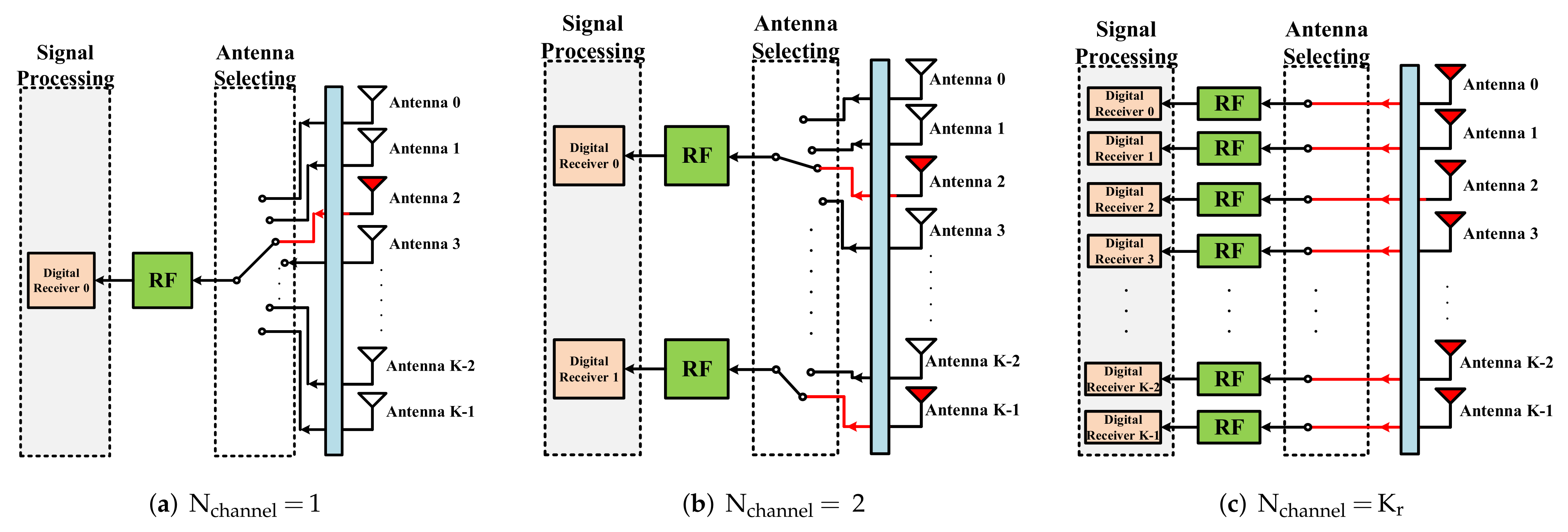
  • Since the CSM-RR uses a digital receiver, multiple channels can be used for simultaneous reception without adding additional hardware overhead. Without adding additional hardware, the CSM-RR greatly improves the efficiency of neighbor discovery.
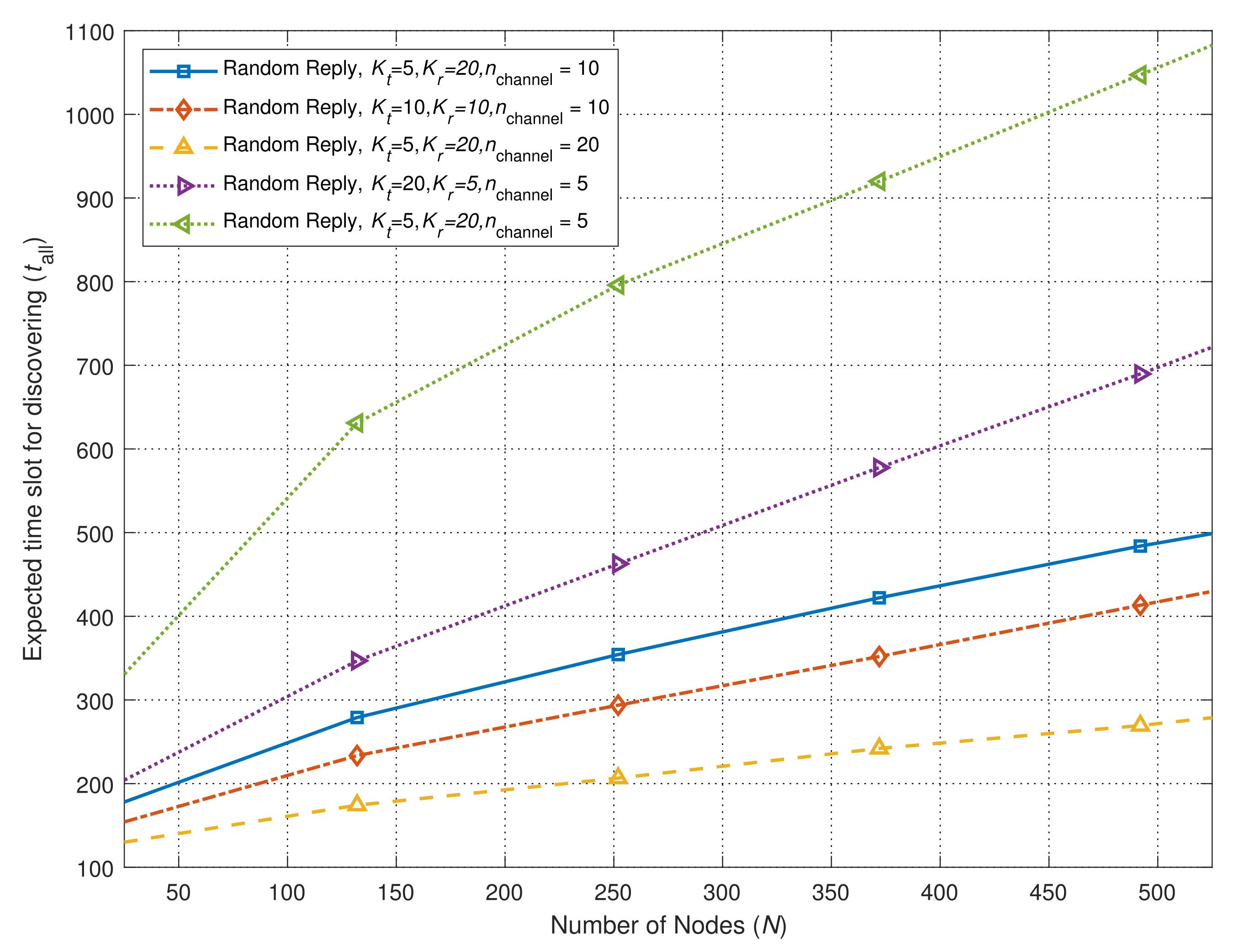
  • By optimizing N channel , α , p reply , β , K , the neighbor discovery time can be further reduced when the number of nodes is large. Simulations have shown that as the network scale is 100 to 500 nodes, the convergence time is 10 times higher than that of the single channel algorithm.
Consequently, the CSM-RR can be used to improve the neighbor discovery performance of FANETs. In this paper, we only consider the expected time slot for neighbor discovery as the performance. In our future work, other metrics such as the exchange of information and the number of control packets will be investigated.

Author Contributions

Y.S.: conceptualization, methodology, writing—original draft preparation; L.Z.: conceptualization, methodology, writing—review and editing; Z.L.: validation, visualization; Z.S.: conceptualization, project administration, writing—original draft preparation; J.Z.: writing—original draft preparation, writing—review and editing; J.A.: conceptualization, project administration. All authors have read and agreed to the published version of the manuscript.

Funding

This research was funded in part by the National Scientific Foundation of China under grants 62101050, 62001022, U1836201.

Conflicts of Interest

The authors declare no conflict of interest.

References

  1. Xiao, Z.; Zhu, L.; Liu, Y.; Yi, P.; Zhang, R.; Xia, X.G.; Schober, R. A Survey on Millimeter-Wave Beamforming Enabled UAV Communications and Networking. IEEE Commun. Surv. Tutor. 2021, 24, 557–610. [Google Scholar] [CrossRef]
  2. Shakhatreh, H.; Sawalmeh, A.H.; Al-Fuqaha, A.; Dou, Z.; Almaita, E.; Khalil, I.; Othman, N.S.; Khreishah, A.; Guizani, M. Unmanned Aerial Vehicles (UAVs): A Survey on Civil Applications and Key Research Challenges. IEEE Access 2019, 7, 48572–48634. [Google Scholar] [CrossRef]
  3. Li, B.; Fei, Z.; Zhang, Y. UAV Communications for 5G and Beyond: Recent Advances and Future Trends. IEEE Internet Things J. 2019, 6, 2241–2263. [Google Scholar] [CrossRef] [Green Version]
  4. Urama, J.; Wiren, R.; Galinina, O.; Kauppi, J.; Hiltunen, K.; Erkkila, J.; Chernogorov, F.; Etelaaho, P.; Heikkila, M.; Torsner, J.; et al. UAV-Aided Interference Assessment for Private 5G NR Deployments: Challenges and Solutions. IEEE Commun. Mag. 2020, 58, 89–95. [Google Scholar] [CrossRef]
  5. Lin, J.; Cai, W.; Zhang, S.; Fan, X.; Guo, S.; Dai, J. A Survey of Flying Ad-Hoc Networks: Characteristics and Challenges. In Proceedings of the 2018 Eighth International Conference on Instrumentation Measurement, Computer, Communication and Control (IMCCC), Harbin, China, 19–21 July 2018; pp. 766–771. [Google Scholar] [CrossRef]
  6. Liu, Y.; Luo, Z.; Liu, Z.; Shi, J.; Cheng, G. Cooperative Routing Problem for Ground Vehicle and Unmanned Aerial Vehicle: The Application on Intelligence, Surveillance, and Reconnaissance Missions. IEEE Access 2019, 7, 63504–63518. [Google Scholar] [CrossRef]
  7. Xiao, M.; Mumtaz, S.; Huang, Y.; Dai, L.; Li, Y.; Matthaiou, M.; Karagiannidis, G.K.; Björnson, E.; Yang, K.; I, C.L.; et al. Millimeter Wave Communications for Future Mobile Networks. IEEE J. Sel. Areas Commun. 2017, 35, 1909–1935. [Google Scholar] [CrossRef] [Green Version]
  8. Wang, X.; Kong, L.; Kong, F.; Qiu, F.; Xia, M.; Arnon, S.; Chen, G. Millimeter Wave Communication: A Comprehensive Survey. IEEE Commun. Surv. Tutor. 2018, 20, 1616–1653. [Google Scholar] [CrossRef]
  9. Uwaechia, A.N.; Mahyuddin, N.M. A Comprehensive Survey on Millimeter Wave Communications for Fifth-Generation Wireless Networks: Feasibility and Challenges. IEEE Access 2020, 8, 62367–62414. [Google Scholar] [CrossRef]
  10. Zhang, L.; Zhao, H.; Hou, S.; Zhao, Z.; Xu, H.; Wu, X.; Wu, Q.; Zhang, R. A Survey on 5G Millimeter Wave Communications for UAV-Assisted Wireless Networks. IEEE Access 2019, 7, 117460–117504. [Google Scholar] [CrossRef]
  11. Niu, Y.; Li, Y.; Jin, D.; Su, L.; Vasilakos, A.V. A survey of millimeter wave communications (mmWave) for 5G: Opportunities and challenges. Wirel. Netw. 2015, 21, 2657–2676. [Google Scholar] [CrossRef]
  12. Yang, A.; Li, B.; Yan, Z.; Yang, M. A Bi-Directional Carrier Sense Collision Avoidance Neighbor Discovery Algorithm in Directional Wireless Ad Hoc Sensor Networks. Sensors 2019, 19, 2120. [Google Scholar] [CrossRef] [PubMed] [Green Version]
  13. Park, H.; Kim, Y.; Song, T.; Pack, S. Multiband Directional Neighbor Discovery in Self-Organized mmWave Ad Hoc Networks. IEEE Trans. Veh. Technol. 2015, 64, 1143–1155. [Google Scholar] [CrossRef]
  14. Nur, F.N.; Sharmin, S.; Habib, M.A.; Razzaque, M.A.; Islam, M.S.; Almogren, A.; Hassan, M.M.; Alamri, A. Collaborative neighbor discovery in directional wireless sensor networks: Algorithm and analysis. Eurasip J. Wirel. Commun. Netw. 2017, 2017, 119. [Google Scholar] [CrossRef] [Green Version]
  15. Zhang, Z.; Li, B. Neighbor discovery in mobile ad hoc self-configuring networks with directional antennas: Algorithms and comparisons. IEEE Trans. Wirel. Commun. 2008, 7, 1540–1549. [Google Scholar] [CrossRef]
  16. Bai, W.; Xu, Y.; Wang, J.; Xu, R.; Anpalagan, A.; Chen, C.; Xu, Y.; Wang, X. Cognitive Neighbor Discovery With Directional Antennas in Self-Organizing IoT Networks. IEEE Internet Things J. 2021, 8, 6865–6877. [Google Scholar] [CrossRef]
  17. Liu, B.; Rong, B.; Hu, R.Q.; Qian, Y. Neighbor discovery algorithms in directional antenna based synchronous and asynchronous wireless ad hoc networks. IEEE Wirel. Commun. 2013, 20, 106–112. [Google Scholar] [CrossRef]
  18. Bilgin, Y.A.; Yılmaz, A.O. Neighbor discovery in network with directional antennas. In Proceedings of the 2013 21st Signal Processing and Communications Applications Conference (SIU), Haspolat, Turkey, 24–26 April 2013; pp. 1–4. [Google Scholar] [CrossRef]
  19. Vasudevan, S.; Kurose, J.; Towsley, D. On neighbor discovery in wireless networks with directional antennas. In Proceedings of the IEEE 24th Annual Joint Conference of the IEEE Computer and Communications Societies, Miami, FL, USA, 13–17 March 2005; Volume 4, pp. 2502–2512. [Google Scholar] [CrossRef] [Green Version]
  20. Cai, H.; Wolf, T. On 2-way neighbor discovery in wireless networks with directional antennas. In Proceedings of the 2015 IEEE Conference on Computer Communications (INFOCOM), Hong Kong, China, 26 April–1 May 2015; pp. 702–710. [Google Scholar] [CrossRef]
  21. Chen, L.; Li, Y.; Vasilakos, A.V. On Oblivious Neighbor Discovery in Distributed Wireless Networks with Directional Antennas: Theoretical Foundation and Algorithm Design. IEEE/ACM Trans. Netw. 2017, 25, 1982–1993. [Google Scholar] [CrossRef] [Green Version]
  22. Wang, Y.; Liu, B.; Gui, L. Adaptive Scan-based Asynchronous Neighbor Discovery in wireless networks using directional antennas. In Proceedings of the 2013 International Conference on Wireless Communications and Signal Processing, Hangzhou, China, 24–26 October 2013; pp. 1–6. [Google Scholar] [CrossRef]
  23. Sivanantham, E.; Ramakrishnan, M. Energy-efficient sustainable cluster based neighbor discovery technique for wireless networks with directional antennas. Clust. Comput.-J. Netw. Softw. Tools Appl. 2017, 20, 1527–1534. [Google Scholar] [CrossRef]
  24. Wang, Y.; Mao, S.; Rappaport, T.S. On Directional Neighbor Discovery in mmWave Networks. In Proceedings of the 2017 IEEE 37th International Conference on Distributed Computing Systems (ICDCS), Atlanta, GA, USA, 5–8 June 2017; pp. 1704–1713. [Google Scholar] [CrossRef]
  25. Cai, H.; Liu, B.; Gui, L.; Wu, M.Y. Neighbor discovery algorithms in wireless networks using directional antennas. In Proceedings of the 2012 IEEE International Conference on Communications (ICC), Ottawa, ON, Canada, 10–15 June 2012; pp. 767–772. [Google Scholar] [CrossRef]
  26. Tarnai, T. The observed form of coated vesicles and a mathematical covering problem. J. Mol. Biol. 1991, 218, 485–488. [Google Scholar] [CrossRef]
  27. Leopardi, P. A partition of the unit sphere into regions of equal area and small diameter. Electron. Trans. Numer. Anal. 2006, 25, 2006. [Google Scholar]
Figure 1. The important role of drones in disaster relief.
Electronics 11 01566 g001
Figure 2. The 3D model of the direction antenna.
Electronics 11 01566 g002
Figure 3. Neighbor discovery in sector model.
Electronics 11 01566 g003
Figure 4. Link established cases.
Electronics 11 01566 g004
Figure 5. Multi-channel model.
Electronics 11 01566 g005
Figure 6. The sector switches in beacon dispatch.
Electronics 11 01566 g006
Figure 7. An example of beacon dispatch. (a) All cluster members are in fast scan mode. (b) The cluster head starts to send beacon frames in the first sector. (c) Cluster member 1 has locked the sector. (d) The cluster head sends beacon frames continuously until cluster member 2 switches to the sector pointing to the cluster head. (e) Cluster member 2 has pointed at the cluster head. (f) Cluster member 2 has locked the sector.
Electronics 11 01566 g007
Figure 8. Fixed reply mechanism.
Electronics 11 01566 g008
Figure 9. Neighbor discovery with random reply mechanism ( N = 6 ).
Electronics 11 01566 g009
Figure 10. Comparison between neighbor discovery algorithm with fixed reply (K = 4).
Electronics 11 01566 g010
Figure 11. Comparison between neighbor discovery algorithm with random reply ( K = 4 ).
Electronics 11 01566 g011
Figure 12. Time for discovery with different K. ( N = 1200 ).
Electronics 11 01566 g012
Figure 13. Symmetric K r and K t with different numbers of receivers.
Electronics 11 01566 g013
Figure 14. Discovery time vs. p reply .
Electronics 11 01566 g014
Figure 15. Time for discovery vs. β .
Electronics 11 01566 g015
Figure 16. Fraction of discovery vs. β .
Electronics 11 01566 g016
Figure 17. Time for discovery vs. different location.
Electronics 11 01566 g017
Figure 18. PMF of location distribution.
Electronics 11 01566 g018
Table 1. Related Works.
AlgorithmFeatureYearsReference
BD-SBAThe link layer is based on IEEE 802.11. Carrier sense of the BD-SBA algorithm is performed in the first broadcast step which can reduce the collision of broadcasting the scanning request frames.2019[12]
MDNDUse the 2.4-GHz band with the omnidirectional antennas.The data transmissions are performed by using the 60-GHz band with directional antennas.2015[13]
Gossip-Based AlgorithmNodes gossip about their neighbors’ location information to accelerate the discovery. However, the synchronous algorithms need additional hardware or GPS support.2005[19]
1-way NDEach device periodically transmits advertisement messages to announce its neighbors. When the neighbors receive the advertisement information, it determines that the neighbor discovery is successful.2015[20]
2-way NDOnce a device receives an advertisement message, it provides an active response to its neighbor. This allows neighbor nodes to discover each other.2015[20]
I-SBAAn extra mode named ‘idle’ is added in every time slot. When the node receives a new advisement information successfully, it will not always respond but with probability p.2012[25]
PRASend HELLO packets with probability p at the beginning of each time slot in a random direction, which makes all nodes transmit and receive in different directions that decreases the collision probability.2008[15]
Publisher’s Note: MDPI stays neutral with regard to jurisdictional claims in published maps and institutional affiliations.

