Article

Visible-Light CDMA Communications Using Inverted Spread Sequences

1
Department of Management and Information, Yokohama College of Commerce, Yokohama 230-8577, Japan
2
Graduate School of Information Sciences, Hiroshima City University, Hiroshima 731-3194, Japan
3
Japan Organization for Employment of the Elderly, Persons with Disabilities and Job Seekers, Chiba City 261-8558, Japan
*
Author to whom correspondence should be addressed.
Electronics 2022, 11(12), 1823; https://doi.org/10.3390/electronics11121823
Submission received: 7 May 2022 / Revised: 2 June 2022 / Accepted: 6 June 2022 / Published: 8 June 2022
(This article belongs to the Special Issue New Technologies in Visible Light Communications)

Abstract

:
Visible-light communication (VLC) using light-emitting diodes (LEDs) is gaining attention in the wireless communication field. LEDs can be used as data transmitters without losing their main functionality as lighting devices. In some VLC applications, such as traffic signs and road signals in intelligent transportation systems, high brightness is required to help people recognize the signs and signals conveyed by the light sources. In this paper, the use of inverted modified prime sequence codes (MPSCs) is shown to be efficient for increasing brightness in an optical code-division multiple access (CDMA) system for VLC, while the original MPSCs, namely non-inverted codes, provide much lower brightness. The average light intensity of a system using an inverted MPSC is several times the intensity of a system using an original MPSC, without losing the capabilities of channel multiplexing and multi-user interference canceling. Average light intensity and normalized fluctuation are investigated for the optical CDMA systems with the original and inverted MPSCs. The results show that the systems with the inverted MPSCs provide higher average light intensity and lower normalized fluctuation than the systems with the original MPSCs do. Moreover, the bit error rates of the systems with the inverted MPSCs are evaluated by computer simulation and compared with those of the systems with the original MPSCs.

1. Introduction

Visible-light communication (VLC) is gaining attention in the wireless communication field because it can provide additional spectrum resources [1]. Due to the rapid development of high-power light-emitting diodes (LEDs) [2,3], the research interest in communications using LED devices has increased [4,5]. LED devices can be used as data transmitters without losing their main functionality as lighting and signaling devices [6,7]. VLC has several advantages compared with radio-wave communications, such as robustness against electromagnetic interference and a high security level against eavesdropping [8,9]. VLC is considered to be useful not only for indoor applications but also for outdoor applications, such as vehicles, traffic lights on roads and railways, and streetlamps in intelligent transportation systems (ITSs) [10]. In some applications, high brightness of the light sources is indispensably required to help people recognize them [11].
Optical code-division multiple access (CDMA) is one of the solutions for transmitting several data streams simultaneously in a VLC system. To date, many classes of signature codes have been studied for optical CDMA [12,13]. Optical signature codes are expected to be unipolar, which means each codeword consists of positive chips, called marks and denoted by 1 s, and null chips, called spaces and denoted by 0 s. Optical orthogonal codes [14] and prime sequence codes (PSCs) [15] are proposed for asynchronous optical CDMA systems. Modified prime sequence codes (MPSCs) [16] and generalized MPSCs (GMPSCs) [17,18] have been developed for synchronous optical CDMA systems. The density of a code is defined as the ratio of marks in its codeword, which determines the average light intensity of the light source. Optical signature codes usually have a low density, which means that the average light intensity of each light source is low even if the light source has the potential for high brightness. For example, PSCs, MPSCs, and GMPSCs constructed from a finite field GF( q ) have the same density of 1 / q . The density of many optical signature codes is much lower than 1 / 2 , because low density leads to low cross-correlation in unipolar codes. In some applications, the light sources for optical CDMA also serve as road or railway traffic signs and signals in ITSs. High brightness is required in such cases to help people recognize the signs and signals. Therefore, we set a goal of attaining an average light intensity more than half of the potential which is the light intensity that non-modulated light sources inherently possess. To attain this goal, we adopted the inverted codes of MPSCs and GMPSCs, referred to as inverted MPSCs hereafter, as introduced in this paper.
MPSCs and GMPSCs have an excellent property of multi-user interference (MUI) cancellation in synchronous optical CDMA, when they are used with a proper cancellation technique. Three major MUI cancellation techniques can remove MUI completely. They are the equal-weight orthogonal (EWO) scheme [19], Shalaby’s scheme [20], and Liu’s scheme [21]. All these schemes have a common advantage, which is error-free performance under an ideal link where the noise can be considered negligible. This feature stems from the special correlation properties of MPSCs and those of GMPSCs.
This paper proposes a new optical CDMA scheme that is suitable for VLC requiring high brightness. The feature of the proposed scheme is to adopt an inverted MPSC as a signature code in combination with MUI cancellation techniques. The density of inverted codes is ( q 1 ) / q , which is much higher than that of the original codes. The EWO scheme and Shalaby’s scheme with an inverted code provide a MUI cancellation property that works as well as that of conventional schemes with a non-inverted code. However, when Liu’s scheme is combined with an inverted code, MUI cannot be canceled. Hence, this paper also presents a modified Liu’s scheme that cancels MUI even if an inverted code is used. Then, we investigate the average light intensity and normalized fluctuation of multiplexed optical signals. The results show that the systems with inverted MPSCs provide a higher average light intensity and lower normalized fluctuation in comparison with the conventional systems. Furthermore, we evaluate the bit error rates (BERs) for the systems with inverted and non-inverted MPSCs by computer simulation.

2. Optical CDMA with MUI Cancellation

2.1. Optical CDMA System and MPSC

In optical CDMA systems using LEDs, intensity modulation and direct detection are employed at the transmitter and the receiver, respectively. Figure 1 illustrates a model of the optical CDMA system in which the proposed inverted MPSC is applied. Information bits from each user’s information source, where 1 k N L 1 , are encoded by inverted MPSC at the user’s encoder with a codeword (or codewords) assigned to the user. The sequences from each encoder drive each LED and optical signals from all the LEDs are transmitted simultaneously and multiplexed spatially. The multiplexed optical signals are received and converted into electrical signals by a photodetector (PD) at each receiver. The converted signal sequence is fed to each user’s decoder, and the decoded data are delivered to each destination.
This optical CDMA system is assumed to be a synchronous system in that the optical signals’ output from each LED are synchronized in codeword units. We let N max be the maximum number of users for the MUI cancellation scheme under consideration, and N L be the number of light sources, where 1 N L N max . It is assumed that each light source such as an LED device is assigned to a single user. Among the N L light sources, N light sources are active ( 0 N N L ). In other words, N users are transmitting some data, while N L N users are not active and not transmitting any data. In this study, each active user transmits binary data I , where I { 0 ,   1 } .
Signature codes for optical CDMA systems are expected to be unipolar. MPSCs [16], sometimes called synchronized prime codes [12] or modified prime codes (MPC) [13], are generally used in synchronous optical CDMA systems. An MPSC is a binary code generated from a prime field GF( p ) and has p 2 codewords with code lengths of p 2 , where p is a prime number. All the codewords have a unique weight value of p . The set of p 2 codewords can be divided into p groups of p codewords. The cross correlation between any two codewords is zero when they belong to the same group. Otherwise, the cross correlation is one.

2.2. Generalized MPSC

It has been reported that MPSCs can be generalized to extension fields other than prime fields [17,18]. The generalized codes are called GMPSCs or generalized MPSCs. A GMPSC is constructed from an extension field GF( q ), where q = p m , p is a prime number, and m is a positive integer. The code has q 2 codewords with a code length of q 2 and a weight of q . These codewords are divided into q groups of q codewords, as with the case of the original MPSCs constructed from a prime field. It is shown that the correlation property of any GMPSC is also the same as that of the original MPSCs. Any GMPSC has the same following correlation property:
Γ ( c i 1 , j 1 , c i 2 , j 2 ) = { q ,   if   i 1 = i 2   and   j 1 = j 2 , 0 ,   if   i 1 = i 2   and   j 1 j 2 , 1 ,   if   i 1 i 2 ,
where q is the size of the finite field and c i , j is the j th codeword in the i th group ( i = 0 ,   1 ,   ,   q 1 ,   and   j = 0 ,   1 ,   ,   q 1 ).
A GMPSC is constructed from an extension field GF( p m ). Let α be a primitive element of GF( p m ). GF( p m ) has p m elements. For example, the set of four elements in GF(4) is { 0 ,   1 ,   α ,   α 2 } , where α 2 + α + 1 = 0 . Following the code construction procedure described below, we first generate a code C * over GF( p m ); then, we transform it into a binary code, that is a GMPSC. The length of the code C * is p m (symbols), and that of the GMPSC is p 2 m (bits).
  • First, set up a generator vector g = ( g 0 ,   g 1 ,   ,   g p m 1 ) , where g i GF( p m ) and no two elements g i and g j ( i j ) are equal. For example, we can choose g = ( 0 ,   1 ,   α ,   α 2 ) for q = 4 .
  • A group coefficient x i ( x i GF( p m )) is selected for each group. No two group coefficients are to be equal. We can choose x 0 = 0 ,   x 1 = 1 ,   x 2 = α ,   and   x 3 = α 2 for q = 4 .
  • Set up p m constant vectors h j ( j = 0 ,   1 ,   ,   p m 1 ) over GF( p m ). The vectors h j have length p m . All elements in a single vector are identical, and no two vectors are the same. We can choose h 0 = ( 0 ,   0 ,   0 ,   0 ) ,   h 1 = ( 1 ,   1 ,   1 ,   1 ) ,   h 2 = ( α ,   α ,   α ,   α ) ,   and   h 3 = ( α 2 ,   α 2 ,   α 2 ,   α 2 ) for q = 4 .
  • Then, the codewords c i , j *   in the code C * over GF( p m ) are generated by the following equation:
    c i , j * = x i g + h j
    for i = 0 ,   1 ,   ,   p m 1 and j = 0 ,   1 ,   ,   p m 1 . Multiplication and addition in Equation (2) are the operations over GF ( p m ) . The p m codewords in the i th group are c i ,   0 * ,   c i ,   1 * ,   ,   c i ,   p m 1 * .
  • Finally, the codewords c i , j * in C * are transformed into binary codewords c i , j , which constitute a GMPSC. Every element in GF( p m ) which appears in a vector c i , j * is transformed into the binary p m -tuple of weight one, and no two tuples are the same. For example, the zero element 0 in GF(4) can be transformed into ‘1000′, 1 into ‘0100′, α into ’0010′, and α 2 into ’0001′.
As an example, a GMPSC with q = 4 is shown in Table 1. This code has sixteen codewords, which are divided into four groups of four codewords. Codewords of the original MPSC constructed from GF( p ) can also be generated using the above procedure by setting the parameter m = 1 . In the original algorithm [16] for MPSCs, codewords are generated by cyclic-shift operation of prime sequences or its binary representation, i.e., prime sequence code (PSC). Although the algorithm for original MPSCs is different from that for GMPSCs, the resulting sets of codewords are equivalent in the case of m = 1 . The cyclic-shift operation for an original MPSC corresponds to the operation ‘ + h j ’ in Equation (2) for a GMPSC. Hereafter, we refer to both original and generalized MPSCs as MPSCs.

2.3. Conventional EWO Scheme

In the conventional EWO scheme [19], N max is given by
N max = q q / 2 ,
where x is the maximum integer that is not greater than the positive real number x . For example, the maximum number of users N max is eight for an MPSC with q = 4 .
Because the EWO scheme employs code-shift keying signaling, this scheme is also referred to as CSK scheme [22,23]. Two codewords, w k , 0 and w k , 1 , in the same group are assigned to the k th user as spread sequences ( k = 0 ,   1 ,   ,   N max 1 ) . When the k th user is active, its encoder selects the codeword w k , 1 for transmission of data I = 1 and w k , 0 for I = 0 . An example of the codeword assignment is shown in Table 2. Figure 2a illustrates a block diagram of the k th user’s encoder. We note that when the k th user is not active, an all-zero sequence is transmitted constantly in the conventional EWO, Shalaby’s, and Liu’s schemes.
Figure 3 illustrates examples of signal sequences corresponding to MPSC codewords and a multiplexed signal sequence for q = 4 , N L = 8 , and N = 4 . In this case, the code length of the MPSC is 16. A slot represents a time period during which one spread sequence is transmitted. In Figure 3, (a) shows the two sequences encoded by the codewords w 2 , 0 and w 2 , 1 , which are assigned to the second user; (b) shows the sequences transmitted simultaneously by four active users, who are the first, second, fifth, and seventh users transmitting data 1, 0, 0, and 1, respectively; and (c) shows the multiplexed sequence of the eight sequences including all-zero sequences transmitted by four non-active users.
The spatially multiplexed optical signals are detected at the receiver and converted into the electric signal sequence r . r   is decoded at each user’s decoder, which consists of two correlators, a difference calculator, and a decision circuit. Figure 2b illustrates a block diagram of the k th user’s decoder. For the EWO scheme, the k th user’s decoder computes Γ 1 and Γ 0 , which are correlations between the received sequence r and the codewords w k , 1 and w k , 0 , respectively. Γ 1 and Γ 0 are represented as follows:
Γ 1 = Γ ( r , w k , 1 ) ,
Γ 0 = Γ ( r , w k , 0 ) ,
where the function Γ ( a , b ) is the inner product of the vectors a and b . Then, the decoder calculates the difference Γ 1 Γ 0 . If the difference is greater than or equal to the threshold zero, the decoder outputs I ^ = 1 as the decoded datum. Otherwise, the decoder outputs I ^ = 0 . Because the threshold in the EWO decoder is always zero, this scheme cancels MUI without needing to estimate the light intensity. The fact that the optimum threshold is zero in the EWO scheme is advantageous when implementing a decoder.
Suppose that the channel is an ideal link where the noise can be considered negligible, and that the light intensity of each user’s positive chip is 1. Let Δ ( I ) be the value Γ 1 Γ 0 when the user transmits data I . At the EWO decoder, Δ ( 1 ) and Δ ( 0 ) are certain to be q and q , respectively; for any number of active users, N less than or equal to N max . | Δ ( 1 ) Δ ( 0 ) | is defined as the decision distance [24], which is a useful index for evaluating the error resistance property of MUI cancellation schemes. The decision distance of the EWO scheme is 2 q .

2.4. Conventional Shalaby’s Scheme

In Shalaby’s scheme, one codeword in each group of MPSCs is reserved from being assigned to any user [20]. Each of these q codewords is referred to as a reference word to estimate the number of interfering users. The maximum number of users N max to which the codewords can be assigned is q 2 q . An example of the codeword assignment for Shalaby’s scheme is also shown in Table 2. In Table 2, y i is the reference word in the i th group for i = 0 ,   1 ,   ,   q 1 . Because this cancellation scheme is based on on–off keying (OOK) signaling, the k th user’s encoder outputs the codeword w k , 1 when I = 1 , and it outputs the all-zero sequence when I = 0 ( k = 0 ,   1 ,   ,   q 2 q 1 ).
The block diagrams illustrated in Figure 2a,b are also applied to the encoder and decoder of Shalaby’s scheme, respectively. For Shalaby’s scheme, w k , 0 in the encoder is an all-zero sequence with a length of q 2 . At the k th user’s decoder, Correlator 1 computes Γ 1 , which is the correlation between the received sequence r and the assigned codeword w k , 1 . Correlator 0 computes Γ 0 , which is the correlation between r and y i where y i is the reference word in the same group with w k , 1 . Γ 1 and Γ 0 are represented as follows:
Γ 1 = Γ ( r , w k , 1 ) ,
Γ 0 = Γ ( r , y i ) ,
where i = k / ( q 1 ) . Then, the decoder calculates the difference Γ 1 Γ 0 . If the difference is greater than or equal to the threshold, the decision circuit outputs I ^ = 1 . Otherwise, it outputs I ^ = 0 . The ideal threshold is q / 2 when we suppose that the light intensity of each user’s positive chip is 1. Shalaby’s scheme cancels MUI completely at the decoder, if the receiver can estimate the received light intensity of a single positive chip correctly. Because Δ ( 1 ) = q and Δ ( 0 ) = 0 for an ideal link, the decision distance of Shalaby’s scheme is q .

2.5. Conventional Liu’s Scheme

In the conventional Liu’s scheme, group information is added to every codeword in MPSCs [21]. This scheme is sometimes called padded MPC [13]. The part indicating the group information requires q chips. If the assigned codeword belongs to the i th group, only the i th chip in that part is 1 and the other chips are 0. Therefore, the length of the spread sequence is q 2 + q and the maximum number of users N max is q 2 . Table 2 also presents an example of the codeword assignment in Liu’s scheme. Because this cancellation scheme is based on OOK signaling, the k th user’s encoder outputs the codeword w k , 1 when I = 1 , and it outputs the all-zero sequence when I = 0 ( k = 0 ,   1 ,   ,   q 2 1 ).
The block diagrams illustrated in Figure 2a,b are also applied to the encoder and decoder of Liu’s scheme, respectively. For Liu’s scheme, w k , 0 in the encoder is an all-zero sequence with a length of q 2 + q . At the k th user’s decoder, Correlator 1 computes the correlation Γ 1 between the received sequence r and the sequence in which the first q 2 chips are the same as those of w k , 1 , and the last q chips are all zeros. In contrast, Correlator 0 computes the correlation Γ 0 between r and the sequence in which the last q chips are the inverted chips of those of w k , 1 and the first q 2 chips are all zeros. For example, Γ 1 and Γ 0 at the fourth user’s decoder are represented as follows:
Γ 1 = Γ ( r ,   ( 1000   0100   0010   0001   0000 ) ) ,
Γ 0 = Γ ( r ,   ( 0000   0000   0000   0000   1011 ) ) ,
where w 4 , 1 = ( 1000   0100   0010   0001   0100 ) . Then, the decoder calculates the difference Γ 1 Γ 0 . If the difference is greater than or equal to the threshold, the decision circuit outputs I ^ = 1 . Otherwise, it outputs I ^ = 0 . The ideal threshold is q / 2 when we suppose that the light intensity of each user’s positive chip is 1. Liu’s scheme cancels MUI completely at the decoder, if the receiver can estimate the received light intensity of a single positive chip correctly. Because Δ ( 1 ) = q and Δ ( 0 ) = 0 for an ideal link, the decision distance in Liu’s scheme is q .
Table 3 compares the properties of the three MUI cancellation schemes using MPSCs from the viewpoints of the spread sequence length n , the maximum number of users N max , and the decision distance d .

3. MUI Cancellation Schemes with Inverted MPSC
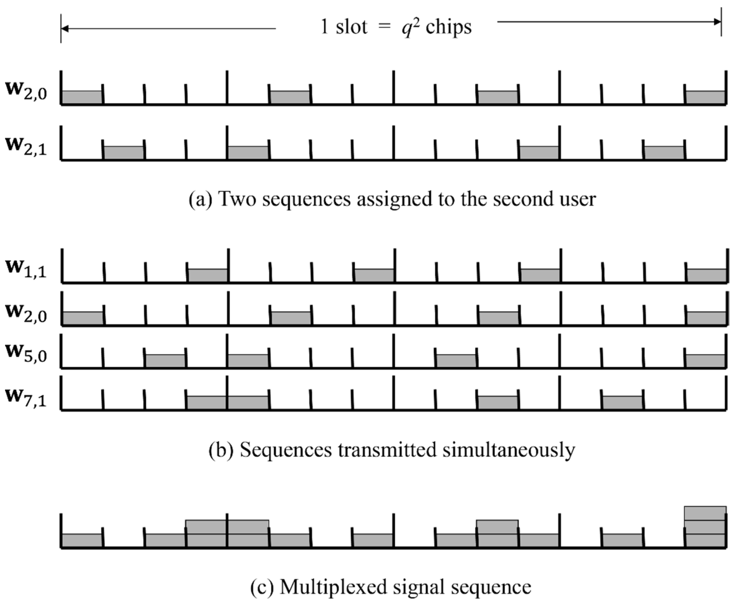
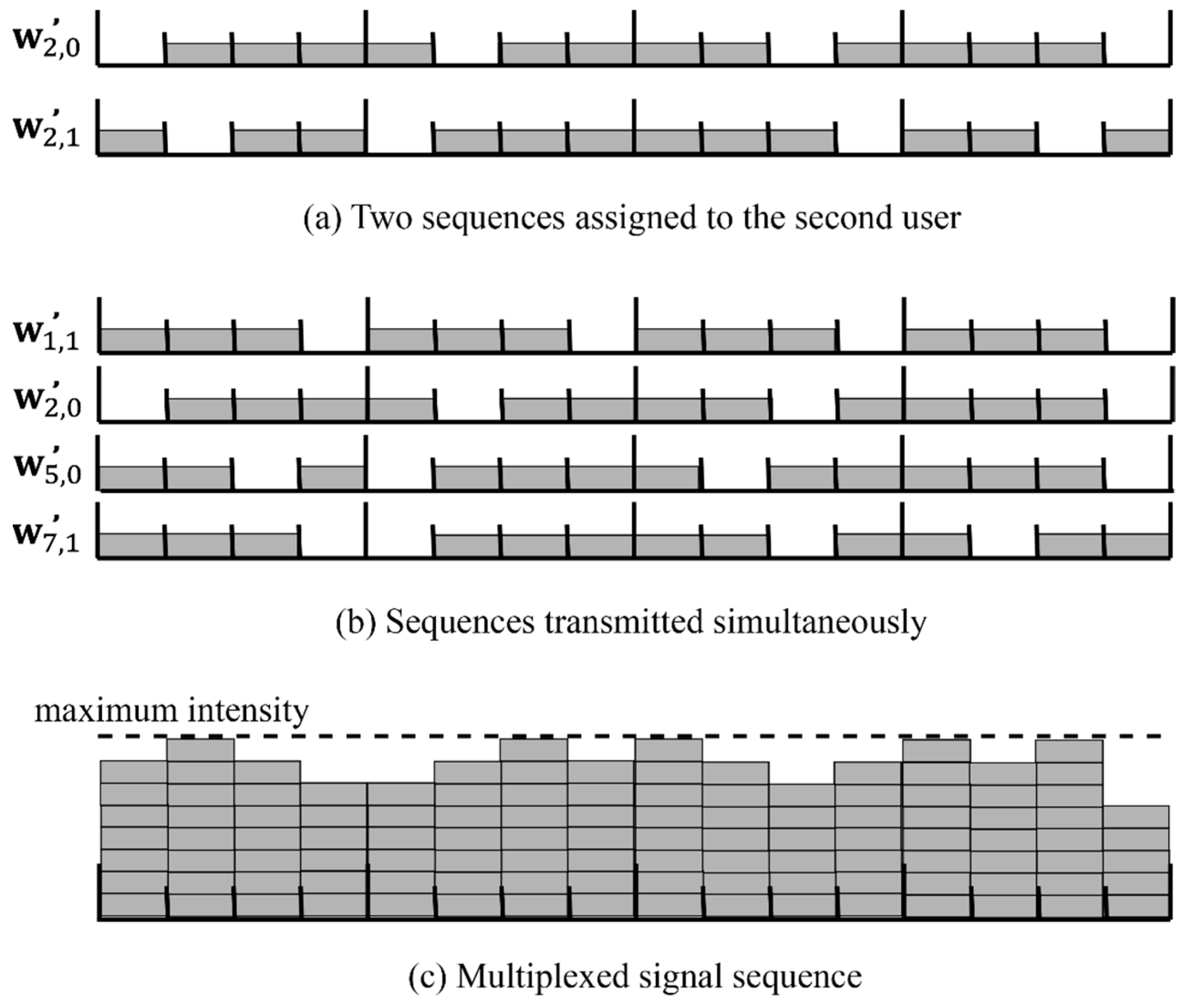
3.1. Inverted MPSC

Although the MPSCs introduced in the previous section have a superior property of canceling MUI, the density of positive chips is 1 / q , which is much lower than 1. Because of the low-density property, the average light intensity of each light source is equal to or lower than 1 / q of its maximum light intensity which is the intensity when the light source is lighting continuously. This feature is not favorable for some application systems, such as traffic signals and signs. We propose an optical CDMA system with high average light intensity. The proposed system employs MUI cancellation schemes and inverted MPSCs described later. In an inverted MPSC, each user’s positive chip in the MPSC codewords is replaced with a null chip and vice versa. Table 4 shows an example of an inverted MPSC and codeword assignment for MUI cancellation schemes which are presented in the rest of this section.
To date, a technique has been introduced for optical pulse-position modulation (PPM) in order to make the average light intensity higher in VLC systems [25]. This technique is called inverted PPM. In this technique, the optical signals at the pulse positions of the conventional PPM are made to be null, and those at the other positions are made to be positive. Although its technique is similar to our proposed technique, the inverted PPM offers single-user transmission while our proposed schemes offer multi-user transmission.

3.2. EWO Scheme with Inverted MPSC

In the EWO scheme with an inverted MPSC, two codewords, w k , 0 and w k , 1 , are assigned to the k th user ( k = 0 ,   1 ,   ,   N max 1 ), where N max = q q / 2 and w k , I is an inverted sequence of w k , I for the conventional EWO scheme ( I { 0 ,   1 } ). An example of codeword assignment for this scheme is shown in Table 4.
The encoder of this scheme is also illustrated by Figure 2a, where the sequences w k , 1 and w k , 0 are replaced with w k , 1 and w k , 0 , respectively. We also note that an all-one sequence is transmitted constantly when the user is not active in the EWO and the other two schemes using an inverted MPSC. Figure 4 shows an example of multiplexing sequences in the EWO scheme with an inverted MPSC with q = 4 , N L = 8 , and N = 4 . In Figure 4, (a) shows the two sequences encoded by the inverted codewords w 2 , 0 and w 2 , 1 , which are assigned to the second user; (b) shows the sequences transmitted simultaneously by four active users, who are the first, second, fifth, and seventh users transmitting data 1, 0, 0, and 1, respectively; and (c) shows the multiplexed sequence of the eight sequences including all-one sequences transmitted by four non-active users. We can see that the multiplexed sequence in Figure 4c is equal to the sequence subtracting the multiplexed sequence in Figure 3c from the constant-level sequence whose level is the maximum light intensity of N L light sources. It is shown that the average light intensity of the multiplexed sequence in Figure 4c is much higher than that of the multiplexed sequence in Figure 3c.
The k th user’s decoder, also illustrated by Figure 2b, computes two correlations between the received sequence r ′ and the two sequences w k , 0 and w k , 1 , where w k , 0 and w k , 1 are non-inverted MPSC codewords. Therefore, the two correlators, Correlator 1 and Correlator 0, are exactly the same as those in the decoder for the conventional EWO scheme. Γ 1 and Γ 0 are outputs of Correlator 1 and Correlator 0, respectively, and are represented by
Γ 1 = Γ ( r , w k , 1 ) ,
Γ 0 = Γ ( r , w k , 0 ) .
The only precaution that needs to be taken is to calculate the difference Γ 0 Γ 1 before the decision circuit, while Γ 1 Γ 0 is calculated by the conventional EWO decoder. If the difference Γ 0 Γ 1 is greater than or equal to the threshold zero, the decoder outputs I ^ = 1 as a decoded datum. Otherwise, the decoder outputs I ^ = 0 .
For an ideal link, Γ 1 and Γ 0 are equal to q N L Γ 1   and   q N L Γ 0 , respectively, where Γ 1 , Γ 0 , Γ 1 , and Γ 0 are given by Equations (4), (5), (10), and (11), respectively. Therefore, the difference Γ 0 Γ 1 is equal to Γ 1 Γ 0 in the conventional EWO scheme. This means that the EWO scheme with an inverted MPSC can cancel MUI completely without estimating the received light intensity and that its decision distance is 2 q .

3.3. Shalaby’s Scheme with Inverted MPSC

In Shalaby’s scheme with an inverted MPSC, one MPSC codeword in each group is used as a reference word in a way similar to that in the conventional Shalaby’s scheme. The other q 2 q MPSC codewords are inverted and assigned to N max users, where N max = q 2 q . An example of the codeword assignment for this Shalaby’s scheme is shown in Table 4. We note that the reference words y 0 , y 1 , y 2 , and y 3 are non-inverted codewords in Table 4.
The k th user’s encoder in this Shalaby’s scheme is also illustrated by Figure 2a, although w k , 1 is replaced with its inverted codeword w k , 1 and w k , 0 is replaced with an all-one sequence having a length of q 2 . The multiplexed sequence of this Shalaby’s scheme is equal to the sequence subtracting the multiplexed sequence of the conventional Shalaby’s scheme from the constant-level sequence whose level is the maximum light intensity of N L light sources.
The k th user’s decoder is also represented as Figure 2b. At the decoder, Correlator 1 computes Γ 1 , which is the correlation between the received sequence r ′ and the non-inverted codeword w k , 1 . Correlator 0 computes Γ 0 , which is the correlation between r ′ and y i , where y i is the reference word in the same group with w k , 1 . Thus, the Correlators 1 and 0 are exactly the same as those in the decoder for the conventional Shalaby’s scheme. Γ 1 and Γ 0 are represented as follows:
Γ 1 = Γ ( r , w k , 1 ) ,
Γ 0 = Γ ( r , y i )   ,
where i = k / ( q 1 ) . Then, the decoder calculates the difference Γ 0 Γ 1 . If the value is greater than or equal to the threshold, the decision circuit outputs I ^ = 1 . Otherwise, it outputs I ^ = 0 . The ideal threshold is q / 2 when we suppose that the light intensity of each user’s positive chip is 1.
For an ideal link, Γ 1 and Γ 0 are equal to q N L Γ 1 and q N L Γ 0 , respectively, where Γ 1 , Γ 0 , Γ 1 , and Γ 0 are given by Equations (6), (7), (12), and (13), respectively. Therefore, the difference Γ 0 Γ 1 is equal to Γ 1 Γ 0 in the conventional Shalaby’s scheme. This means that Shalaby’s scheme with an inverted MPSC cancels MUI completely if the receiver can estimate the received light intensity of a single positive chip correctly and that its decision distance is q .

3.4. Modified Liu’s Scheme with Inverted MPSC

If we use Liu’s scheme with an inverted MPSC in a fashion analogous to that of the other two schemes, it is not possible to decode transmitted data correctly. This is because the numbers of chip locations where two correlations are calculated at the decoder are different. Therefore, we propose a modified Liu’s scheme that can decode data correctly even if an inverted MPSC is used.
In our modified Liu’s scheme, the k th user uses a spread sequence w k , 1 of length q 2 + q + 1 for k = 0 ,   1 ,   ,   N max 1 , where N max = q 2 . The first q 2 + q chips of w k , 1 are the inverted sequence of w k , 1 for the conventional Liu’s scheme, and the last chip of w k , 1 is always a mark. An example of the codeword assignment for the modified Liu’s scheme is shown in Table 4. By using these spread sequences, the numbers of chip locations where two correlations are calculated at the decoder are made to be the same value.
The k th user’s encoder of this scheme is also illustrated by Figure 2a, although w k , 1 is replaced with w k , 1 and w k , 0 is replaced with an all-one sequence with a length of q 2 + q + 1 . The first q 2 + q chips of the multiplexed sequence in this scheme form the same sequence as that obtained by subtracting the multiplexed sequence of the conventional Liu’s scheme from the constant-level sequence whose level is the maximum light intensity of N L light sources. In addition, the last chip of the multiplexed sequence is always equal to the maximum light intensity of N L light sources.
The k th user’s decoder is illustrated by Figure 2b. At the decoder, Correlator 1 computes Γ 1 , which is the correlation of the first q 2 chips between the received sequence r and the non-inverted sequence w k , 1 . Correlator 0 computes Γ 0 , which is the correlation of the last q + 1 chips between r and the inverted sequence w k , 1 . For example, Γ 1 and Γ 0 at the fourth user’s decoder are represented as follows:
Γ 1 = Γ ( r , ( 1000   0100   0010   0001   0000   0 ) ) ,
Γ 0 = Γ ( r , ( 0000   0000   0000   0000   1011   1 ) ) ,
where the spread sequence of the fourth user sending I = 1 is w 4 , 1 = ( 0111   1011   1101   1110   1011   1 ) . Then, the decoder calculates the difference Γ 0 Γ 1 . If the difference is greater than or equal to the threshold, the decision circuit outputs I ^ = 1 . Otherwise, it outputs I ^ = 0 . The ideal threshold is q / 2 when we suppose that the light intensity of each user’s positive chip is 1.
For an ideal link, Γ 1 and Γ 0 are q N L Γ 1 and q N L Γ 0 , respectively, where Γ 1 , Γ 0 , Γ 1 , and Γ 0 are given by Equations (8), (9), (14) and (15), respectively. Therefore, the difference Γ 0 Γ 1 is equal to Γ 1 Γ 0 in the conventional Liu’s scheme. This means that the modified Liu’s scheme with an inverted MPSC can cancel MUI and decode data correctly, as is the case with the conventional Liu’s scheme. The decision distance is also q .
In Table 3, the three MUI cancellation schemes using inverted MPSCs are also compared. As for the EWO scheme and Shalaby’s scheme, spread sequence length n , the maximum number of users N max , and the decision distance d are not different between the non-inverted and inverted forms. As for Liu’s scheme, however, the spread sequence length n for the modified Liu’s scheme is one chip longer than that of the conventional Liu’s scheme, while the other parameters are not different between the non-inverted and inverted forms.

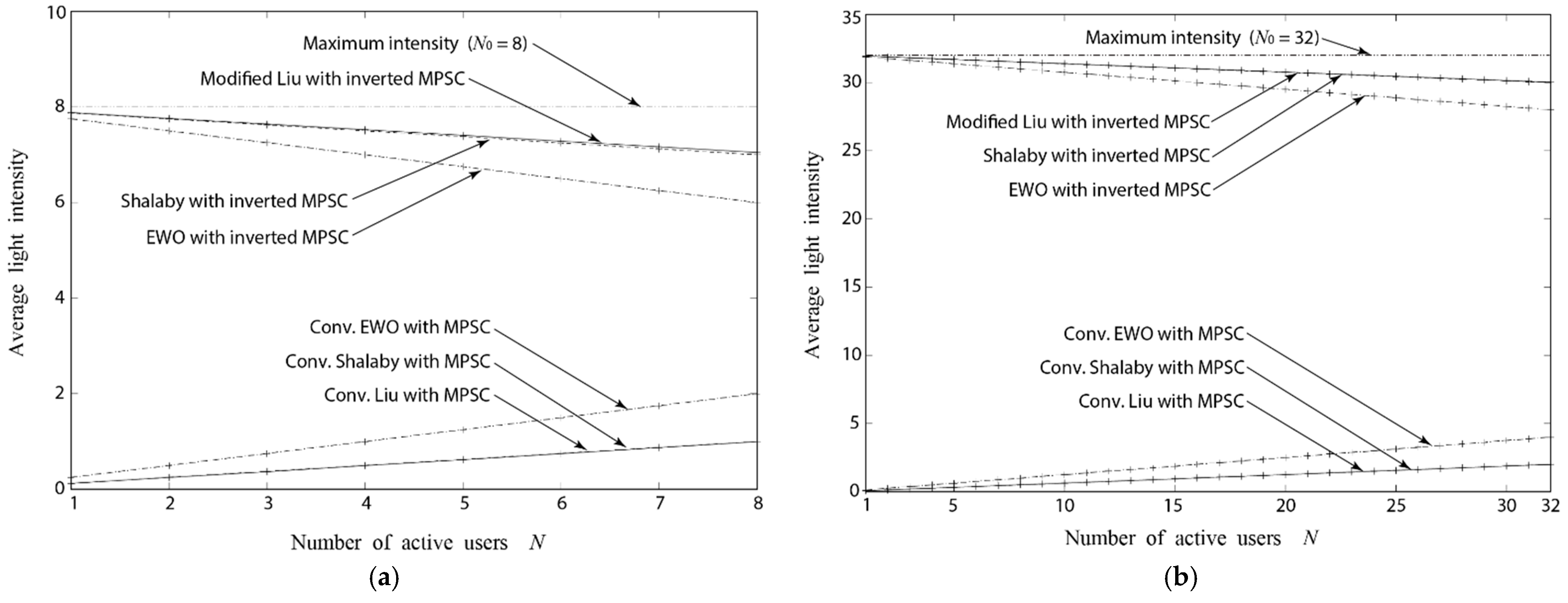
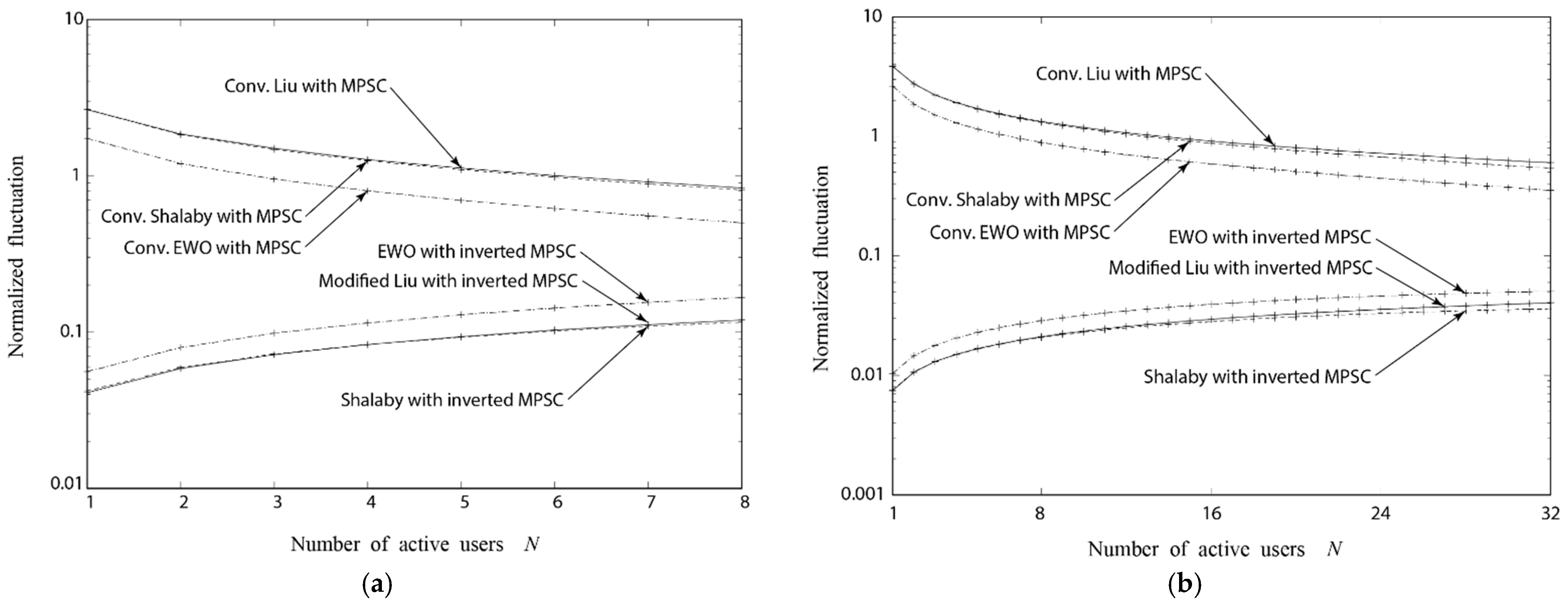
4. Average Light Intensity and Normalized Fluctuation

In this section, we investigate the light intensity and the normalized fluctuation of multiplexed optical signals by computer simulation. We assume an ideal link in which the noise can be considered negligible. MPSCs and inverted MPSCs with lengths of 16 ( q = 4 ) and 64 ( q = 8 ) are employed for the six MUI cancellation schemes introduced in Section 2 and Section 3. Although the maximum number of users N max differs depending on the cancellation scheme, we set up N L = 8 for q = 4 and N L = 32 for q = 8 in all schemes. The number of active users N is set to be 1 N N L . In each slot, N active users are selected randomly among the zeroth to ( N L 1 )th users.
To evaluate fluctuations in light intensity, we define a normalized fluctuation as the ratio of the standard deviation to the average intensity of multiplexed signals. Figure 5 and Figure 6 show comparisons of the average light intensity and the normalized fluctuation, respectively. We assume that the intensity of each user’s positive chip is 1, that the intensity of each user’s null chip is 0, and that the probability of transmitting data I = 0 is equal to the probability of transmitting I = 1 for each user.
Because the positive chips in the non-inverted MPSC codewords are sparse, the average intensity is low and the normalized fluctuation is high for the conventional schemes, as shown in Figure 5 and Figure 6. In contrast, the schemes using an inverted MPSC provide higher average intensity and lower normalized fluctuation because the number of positive chips in an inverted codeword is much greater than that in a non-inverted codeword. Among the three schemes with an inverted MPSC, the EWO scheme has lower average intensity than the other two schemes. The reason is that, in the EWO scheme, the transmitted sequence is a codeword even if I = 0 . These results show that our initial goal of the average light intensity more than half of the maximum light intensity of the light sources is achieved by adopting inverted MPSCs.

5. Bit Error Rate Performance
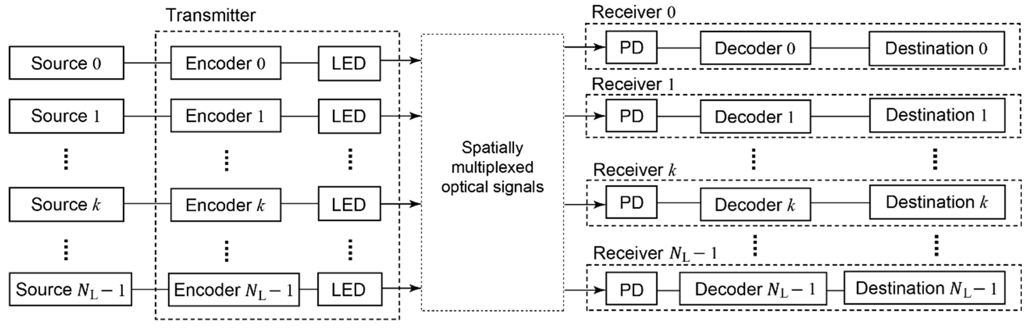
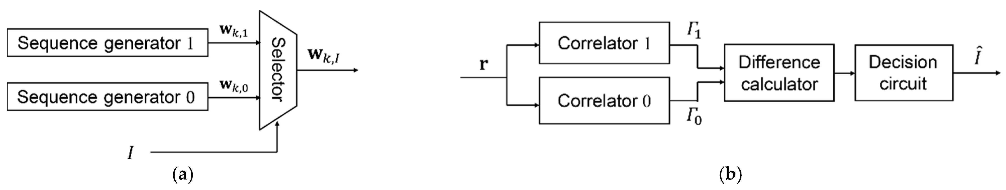
5.1. System Model

All the optical CDMA systems using the six MUI cancellation schemes introduced in Section 2 and Section 3 have a common advantage, which is error-free performance under an ideal link where the noise can be considered negligible.
This section investigates the BER performance of optical CDMA systems with the MUI cancellation schemes described above. We consider that the receiver uses a pin photodiode (pin-PD) to convert an optical signal into an electrical signal at every chip duration. The BERs of these schemes are evaluated by computer simulation. We assume that shot noise and thermal noise are dominant noise sources. It is known that the shot noise distribution can be assumed Gaussian [26,27]. Since the thermal noise distribution is also Gaussian, the distribution of the pin-PD output current can be approximated by a Gaussian distribution with mean μ and variance σ 2 .
The mean of the output current is given by
μ = ρ I s + I b + I d ,
where I s is the photo-current when a single light source is on, I b is the background light current, I d is the dark current, and ρ is the average light intensity when the light intensity of a mark is assumed to be one. For each scheme, ρ is derived as the equations in Table 5. In each equation, the first term is a factor related to the N active users and the others are factors related to the N L N non-active users. Each ρ corresponds to the average light intensity shown in Figure 5 when the modulation extinction ratio M e is large enough. I s and I b are given by
I s = η P w e h f ,
I b = η P b e h f ,
where η is the quantum efficiency, P w is the received signal light power when a light source transmits marks, P b is the received background light power, e is the elementary charge, h is Planck’s constant, and f is the optical frequency.
The variance of the pin-PD output current is given by
σ 2 = σ sh 2 + σ th 2 ,  
where σ sh 2 = 2 e B ( ρ I s + I b + I d ) and σ th 2 = 4 k B B T r / R L are the variance in the shot noise and the variance in the thermal noise, respectively, B is the noise-equivalent bandwidth, k B is Boltzmann’s constant, T r is the receiver noise temperature, and R L is the receiver load resistance. The nominal values of the parameters used in our computer simulation are given in Table 6.

5.2. Bit Error Rate Performance

According to the assumption that the chip duration T c is constant regardless of the schemes, we evaluate P w versus BER performance for the above-mentioned schemes using an MPSC and an inverted MPSC. It is noted that the data rates of the Liu’s and modified Liu’s schemes, having longer sequence lengths n , are lower than those of the other schemes. We assume that the probability of transmitting the data I = 0 is equal to the probability of transmitting I = 1 for each user. We also assume perfect synchronization between the users.
Figure 7a shows the received light power P w versus the BER performance for the six schemes using the MPSC and the inverted MPSC with a length of 16 ( q = 4 ), N L = 8 , and N = 8 . Figure 7b shows the received light power P w versus the BER performance for the six schemes using the MPSC and the inverted MPSC with a length of 64 ( q = 8 ), N L = 32 , and N = 32 . We found that the BERs of the EWO schemes with non-inverted and inverted MPSCs are almost the same, and that they are better than those of the other schemes. The BERs of the schemes with a non-inverted MPSC and an inverted MPSC are nearly identical for Shalaby’s and Liu’s schemes. Because the decision distance for the EWO scheme is twice that of Shalaby’s and Liu’s schemes, the difference in P w is around 3 dBm. The computer simulation results agree well with the theoretical results.

6. Discussion

The authors have developed two visible-light CDMA experimental systems so far [28,29]. Figure 8 shows an experimental system reported in [29]. This system is implemented with an FPGA board (ALTERA Cyclone III 3C120) and five white LEDs (OSW4XME1C1S-100). The developed system adopts the EWO scheme as an MUI cancellation scheme. It can multiplex five data channels on each of which 31.25 kHz MIDI data is transmitted. MIDI data are coded with a non-inverted or an inverted MPSC. The spread sequence length is 16 and the chip rate for each channel is 500 k chips per second. It was confirmed that the system can correctly decode every MIDI datum transmitted simultaneously. Experimental results validated that the capability of channel multiplexing can be maintained even if the inverted sequences are used.
Although the total data rate of 156.25 kbps and the communication distance of 60 cm were achieved with our experimental system, the potential working bandwidth and communication distance would be higher than these values. Recently, many devices have been studied and developed for VLC [2,3,4,5,6,7,8,9]. It is reported that even phosphorescent LEDs and simple OOK modulation enable 100–230 Mbps data rates [3]. By using high-speed and high-power devices, we think that our scheme will achieve a total data rate more than 100 Mbps and a transmission distance of several meters in the near future.
Recently, VLC with a dimming control function has been gaining attention for indoor and outdoor lighting systems [11,30]. Our future work will develop such a VLC system using the technique proposed in the present study.

7. Conclusions

In this paper, we proposed a new optical CDMA system using inverted MPSCs with MUI cancellation schemes incorporated. The proposed system provides higher average light intensity and lower normalized fluctuation than the conventional systems with non-inverted MPSCs without losing the capabilities of channel multiplexing and the MUI canceling. We confirmed that the proposed system achieves our goal of an average light intensity that is more than half of the potential, which is the light intensity that non-modulated light sources inherently possess. Then, we investigated BER performances of the proposed systems in comparison with those of the conventional systems. The results show that the BERs of the systems with a non-inverted MPSC and an inverted MPSC are nearly identical for each MUI cancellation scheme.

Author Contributions

Conceptualization, T.K.M. and S.Y.; methodology, T.K.M.; software, K.O.; validation, T.K.M., S.Y. and K.O.; formal analysis, H.T.; investigation, T.K.M.; resources, T.K.M.; data curation, T.K.M.; writing—original draft preparation, T.K.M.; writing—review and editing, T.K.M.; visualization, K.O.; supervision, T.K.M.; project administration, T.K.M.; funding acquisition, H.T. All authors have read and agreed to the published version of the manuscript.

Funding

This work was supported by the Japan Society for the Promotion of Science KAKENHI Grant Numbers 19K04403, 22K04113, and 22K04091.

Acknowledgments

We express our gratitude to Yasuaki Teramachi. We also express our appreciation to Yuya Murata and Agus Susilo for their help. The results of this work were partly presented at the sixth International Workshop on Signal Design and Its Applications in Communications [28] and the IEICE technical workshop on Wideband System [29].

Conflicts of Interest

The authors declare no conflict of interest.

References

  1. Matheus, L.E.M.; Vieira, A.B.; Vieira, L.F.M.; Vieira, M.A.M.; Gnawali, O. Visible light communication: Concepts, ap-plications and challenges. IEEE Commun. Surv. Tutor. 2019, 21, 3204–3237. [Google Scholar] [CrossRef]
  2. Tsai, C.-L.; Xu, Z.-F. Line-of-sight visible light communications with InGaN-based resonant cavity LEDs. IEEE Photon. Technol. Lett. 2013, 25, 1793–1796. [Google Scholar] [CrossRef]
  3. Khalid, A.M.; Cossu, G.; Corsini, R.; Choudhury, P.; Ciaramella, E. 1-Gb/s Transmission Over a Phosphorescent White LED by Using Rate-Adaptive Discrete Multitone Modulation. IEEE Photon. J. 2012, 4, 1465–1473. [Google Scholar] [CrossRef] [Green Version]
  4. Gancarz, J.; Elgala, H.; Little, T. Impact of lighting requirements on VLC systems. IEEE Commun. Mag. 2013, 51, 34–41. [Google Scholar] [CrossRef]
  5. Jovicic, A.; Li, J.; Richardson, T. Visible light communication: Opportunities, challenges and the path to market. IEEE Commun. Mag. 2013, 51, 26–32. [Google Scholar] [CrossRef]
  6. Lee, K.; Park, H.; Barry, J.R. Indoor Channel Characteristics for Visible Light Communications. IEEE Commun. Lett. 2011, 15, 217–219. [Google Scholar] [CrossRef]
  7. Grubor, J.; Randel, S.; Langer, K.-D.; Walewski, J.W. Broadband information broadcasting using LED-based interior light-ing. IEEE J. Lightwave Tech. 2008, 26, 3883–3892. [Google Scholar] [CrossRef] [Green Version]
  8. Grobe, L.; Paraskevopoulos, A.; Hilt, J.; Schulz, D.; Lassak, F.; Hartlieb, F.; Kottke, C.; Jungnickel, V.; Langer, K.-D. High-speed visible light communication systems. IEEE Commun. Mag. 2013, 51, 60–66. [Google Scholar] [CrossRef]
  9. Khan, L.U. Visible light communication: Applications, architecture, standardization and research challenges. Digit. Commun. Netw. 2017, 3, 78–88. [Google Scholar] [CrossRef] [Green Version]
  10. Memedi, A.; Dressler, F. Vehicular Visible Light Communications: A Survey. IEEE Commun. Surv. Tutor. 2020, 23, 161–181. [Google Scholar] [CrossRef]
  11. Beguni, C.; Căilean, A.-M.; Avătămăniței, S.-A.; Dimian, M. Analysis and Experimental Investigation of the Light Dimming Effect on Automotive Visible Light Communications Performances. Sensors 2021, 21, 4446. [Google Scholar] [CrossRef] [PubMed]
  12. Yang, G.C.; Kwong, W.C. Prime Codes with Applications to CDMA Optical and Wireless Networks; Artech House: Norwood, MA, USA, 2002. [Google Scholar]
  13. Shiraz, H.G.; Karbassian, M.M. Optical CDMA Networks: Principles, Analysis and Applications; John Wiley & Sons: Chichester, UK, 2012; pp. 29–114. [Google Scholar]
  14. Chung, F.R.K.; Salehi, J.A.; Wei, V.K. Optical orthogonal codes: Design, analysis and applications. IEEE Trans. Inf. Theory 1989, 35, 595–604. [Google Scholar] [CrossRef]
  15. Shaar, A.; Davies, P. Prime sequences: Quasi-optimal sequences for OR channel code division multiplexing. Electron. Lett. 1983, 19, 888–890. [Google Scholar] [CrossRef]
  16. Kwong, W.; Perrier, P.; Prucnal, P. Performance comparison of asynchronous and synchronous code-division multiple-access techniques for fiber-optic local area networks. IEEE Trans. Commun. 1991, 39, 1625–1634. [Google Scholar] [CrossRef]
  17. Matsushima, T.K.; Teramachi, Y. Generalized MPSC and its performance in synchronous optical CDMA systems. In Proceedings of the International Symposium on Information Theory and its Applications (ISITA), Seoul, Korea, 3–5 October 2006. [Google Scholar]
  18. Matsushima, T.K.; Nagao, T.; Ochiai, N.; Teramachi, Y. Generalization of modified prime sequence codes and its properties. IEICE Trans. Fundam. 2008, 91, 559–573. [Google Scholar]
  19. Ochiai, N.; Kushibiki, S.; Matsushima, T.K.; Teramachi, Y. Performance analysis of synchronous optical CDMA systems with EWO signaling. IEICE Trans. Fundam. 2003, 86, 37–48, Translates in Electron. Commun. Jpn. Part III Fundam. Electron. Sci. 2004, 87, 37–48. [Google Scholar] [CrossRef]
  20. Shalaby, H.; Sourour, E. Co-channel interference cancellation in optical synchronous CDMA communication systems. In Proceedings of the IEEE International Symposium on Spread Spectrum Techniques and Applications, Oulu, Finland, 4–6 July 1994. [Google Scholar] [CrossRef]
  21. Liu, M.-Y.; Tsao, H.-W. Cochannel interference cancellation via employing a reference correlator for synchronous optical CDMA systems. Microw. Opt. Technol. Lett. 2000, 25, 390–392. [Google Scholar] [CrossRef]
  22. Habuchi, H.; Ono, F. Optical Code Shift Keying with Modified Prime Sequences; Technical Report for Institute of Electronics, Information and Communication Engineers: Tokyo, Japan, 2003; pp. 49–54. [Google Scholar]
  23. Tanaka, S.; Usami, S. Consideration on Multiplexing Code Shift Keying on Optical CDMA System. IEEJ Trans. Electron. Inf. Syst. 2010, 130, 2174–2175. [Google Scholar] [CrossRef]
  24. Matsushima, T.K.; Kakuyama, M.; Murata, Y.; Teramachi, Y.; Yamasaki, S. A Study on Multi-User Interference Cancellers for Synchronous Optical CDMA Systems—Decision Distance and Bit Error Rate. IEICE Trans. Fundam. Electron. Commun. Comput. Sci. 2017, 100, 2135–2145. [Google Scholar] [CrossRef]
  25. Sugiyama, H.; Haruyama, S.; Nakagawa, M. Experimental investigation of modulation method for visible-light communica-tions. IEICE Trans. Commun. 2006, 89, 3393–3400. [Google Scholar] [CrossRef]
  26. Xu, F.; Khalighi, M.-A.; Bourennane, S. Impact of different noise sources on the performance of PIN- and APD-based FSO receivers. In Proceedings of the 11th International Conference on Telecommunications, Graz, Austria, 15–17 June 2011; pp. 211–218. [Google Scholar]
  27. Hui, R. Photodetectors. In Introduction to Fiber-Optic Communications, 1st ed.; Academic Press; Elsevier: Cambridge, MA, USA; London, UK, 2020; pp. 209–297. [Google Scholar]
  28. Matsushima, T.K.; Sasaki, S.; Kakuyama, M.; Yamasaki, S.; Murata, Y. A visible-light communication system using optical CDMA with inverted MPSC. In Proceedings of the International Workshop on Signal Design and Its Applications in Communications (IWSDA), Tokyo, Japan, 20–24 October 2013; pp. 52–55. [Google Scholar]
  29. Kawamoto, R.; Nakamura, S.; Matsushima, T.K.; Miyazaki, S.; Omura, K.; Yamasaki, S. Development of Visible-Light CDM Experimental System Using MPSC and MUI Canceller; Technical Report for Institute of Electronics, Information and Communication Engineers: Tokyo, Japan, October 2017; pp. 1–6. [Google Scholar]
  30. Rajagopal, S.; Roberts, R.D.; Lim, S.-K. IEEE 802.15.7 visible light communication: Modulation schemes and dimming support. IEEE Commun. Mag. 2012, 50, 72–82. [Google Scholar] [CrossRef]
Figure 1. Model of an optical CDMA system.
Electronics 11 01823 g001
Figure 2. Block diagram of the k th user’s encoder and decoder. (a) Block diagram of the encoder, (b) Block diagram of the decoder.
Electronics 11 01823 g002
Figure 3. Examples of signal sequences for the EWO scheme.
Electronics 11 01823 g003
Figure 4. Examples of signal sequences for the EWO scheme with an inverted MPSC.
Electronics 11 01823 g004
Figure 5. Comparisons of average light intensity. (a) q = 4 , N L = 8 ,   and   1 N 8, (b) q = 8 , N L = 32 ,   and   1 N 32.
Electronics 11 01823 g005
Figure 6. Comparisons of normalized fluctuation. (a) q = 4 , N L = 8 ,   and   1 N 8, (b) q = 8 , N L = 32 ,   and   1 N 32.
Electronics 11 01823 g006
Figure 7. Comparisons of P w versus BER performance. (a) q = 4 ,   N L = 8 ,   and   N = 8 , (b)   q = 8 ,   N L = 32 ,   and   N = 32 .
Electronics 11 01823 g007
Figure 8. Visible-light CDMA experimental system using the proposed scheme.
Electronics 11 01823 g008
Table 1. An example of generalized MPSC ( q = 4 ).
Group x i Code   C * Generalized MPSC
i = 0 x 0 = 0 c 0 , 0 * = ( 0 ,   0 ,   0 ,   0 ) c 0 , 1 = ( 1000   1000   1000   1000 )
c 0 , 1 * = ( 1 ,   1 ,   1 ,   1 ) c 0 , 1 = ( 0100   0100   0100   0100 )
c 0 , 2 * = ( α ,   α ,   α ,   α ) c 0 , 2 = ( 0010   0010   0010   0010 )
c 0 , 3 * = ( α 2 ,   α 2 ,   α 2 , α 2 ) c 0 , 3 = ( 0001   0001   0001   0001 )
i = 1 x 1 = 1 c 1 , 0 * = ( 0 ,   1 ,   α ,   α 2 ) c 1 , 0 = ( 1000   0100   0010   0001 )
c 1 , 1 * = ( 1 ,   0 ,   α 2 ,   α ) c 1 , 1 = ( 0100   1000   0001   0010 )
c 1 , 2 * = ( α ,   α 2 ,   0 ,   1 ) c 1 , 2 = ( 0010   0001   1000   0100 )
c 1 , 3 * = ( α 2 ,   α ,   1 ,   0 ) c 1 , 3 = ( 0001   0010   0100   1000 )
i = 2 x 2 = α c 2 , 0 * = ( 0 , α ,   α 2 ,   1 ) c 2 , 0 = ( 1000   0010   0001   0100 )
c 2 , 1 * = ( 1 , α 2 ,   α ,   0 ) c 2 , 1 = ( 0100   0001   0010   1000 )
c 2 , 2 * = ( α ,   0 ,   1 , α 2 ) c 2 , 2 = ( 0010   1000   0100   0001 )
c 2 , 3 * = ( α 2 ,   1 ,   0 , α ) c 2 , 3 = ( 0001   0100   1000   0010 )
i = 3 x 3 = α 2 c 3 , 0 * = ( 0 ,   α 2 ,   1 ,   α ) c 3 , 0 = ( 1000   0001   0100   0010 )
c 3 , 1 * = ( 1 ,   α ,   0 ,   α 2 ) c 3 , 1 = ( 0100   0010   1000   0001 )
c 3 , 2 * = ( α ,   1 , α 2 ,   0 ) c 3 , 2 = ( 0010   0100   0001   1000 )
c 3 , 3 * = ( α 2 ,   0 ,   α ,   1 ) c 3 , 3 = ( 0001   1000   0010   0100 )
Table 2. Codeword assignment for MPSC ( q = 4 ).
MPSC   ( q   =   4 ) Codeword Assignment
GroupCodewordEWOShalabyLiu
i = 0 c 0 , 0 = ( 1000   1000   1000   1000 ) w 0 , 0 = c 0 , 0 y 0 = c 0 , 0 w 0 , 1 = ( 1000   1000   1000   1000   1000 )
c 0 , 1 = ( 0100   0100   0100   0100 ) w 0 , 1 = c 0 , 1 w 0 , 1 = c 0 , 1 w 1 , 1 = ( 0100   0100   0100   0100   1000 )
c 0 , 2 = ( 0010   0010   0010   0010 ) w 1 , 0 = c 0 , 2 w 1 , 1 = c 0 , 2 w 2 , 1 = ( 0010   0010   0010   0010   1000 )
c 0 , 3 = ( 0001   0001   0001   0001 ) w 1 , 1 = c 0 , 3 w 2 , 1 = c 0 , 3 w 3 , 1 = ( 0001   0001   0001   0001   1000 )
i = 1 c 1 , 0 = ( 1000   0100   0010   0001 ) w 2 , 0 = c 1 , 0 y 1 = c 1 , 0 w 4 , 1 = ( 1000   0100   0010   0001   0100 )
c 1 , 1 = ( 0100   1000   0001   0010 ) w 2 , 1 = c 1 , 1 w 3 , 1 = c 1 , 1 w 5 , 1 = ( 0100   1000   0001   0010   0100 )
c 1 , 2 = ( 0010   0001   1000   0100 ) w 3 , 0 = c 1 , 2 w 5 , 1 = c 1 , 2 w 6 , 1 = ( 0010   0001   1000   0100   0100 )
c 1 , 3 = ( 0001   0010   0100   1000 ) w 3 , 1 = c 1 , 3 w 5 , 1 = c 1 , 3 w 7 , 1 = ( 0001   0010   0100   1000   0100 )
i = 2 c 2 , 0 = ( 1000   0010   0001   0100 ) w 4.0 = c 2 , 0 y 2 = c 2 , 0 w 8 , 1 = ( 1000   0010   0001   0100   0100 )
c 2 , 1 = ( 0100   0001   0010   1000 ) w 4 , 1 = c 2 , 1 w 6 , 1 = c 2 , 1 w 9 , 1 = ( 0100   0001   0010   1000   0100 )
c 2 , 2 = ( 0010   1000   0100   0001 ) w 5 , 0 = c 2 , 2 w 7 , 1 = c 2 , 2 w 10 , 1 = ( 0010   1000   0100   0001   0100 )
c 2 , 3 = ( 0001   0100   1000   0010 ) w 5 , 1 = c 2 , 3 w 8 , 1 = c 2 , 3 w 11 , 1 = ( 0001   0100   1000   0010   0100 )
i = 3 c 3 , 0 = ( 1000   0001   0100   0010 ) w 6 , 0 = c 3 , 0 y 3 = c 3 , 0 w 12 , 1 = ( 1000   0001   0100   0010   0100 )
c 3 , 1 = ( 0100   0010   1000   0001 ) w 6 , 1 = c 3 , 1 w 9 , 1 = c 3 , 1 w 13 , 1 = ( 0100   0010   1000   0001   0100 )
c 3 , 2 = ( 0010   0100   0001   1000 ) w 7 , 0 = c 3 , 2 w 10 , 1 = c 3 , 2 w 14 , 1 = ( 0010   0100   0001   1000   0100 )
c 3 , 3 = ( 0001   1000   0010   0100 ) w 7 , 1 = c 3 , 3 w 11 , 1 = c 3 , 3 w 15 , 1 = ( 0001   1000   0010   0100   0100 )
Table 3. Properties of MUI cancellation schemes.
CodeMPSCInverted MPSC
MUI Cancellation SchemeEWOShalabyLiuEWOShalabyModified Liu
Spread   sequence   length   n q 2 q 2 q 2 + q q 2 q 2 q 2 + q + 1
Maximum   number   of   users   N max q q / 2 q 2 q q 2 q q / 2 q 2 q q 2
Decision   distance   d 2 q q q 2 q q q
Table 4. Codeword assignment for inverted MPSC ( q = 4 ).
Inverted   MPSC   ( q   =   4 ) Codeword Assignment
GroupCodewordEWOShalabyModified Liu
i = 0 c 0 , 0 ¯ = ( 0111   0111   0111   0111 ) w 0 , 0 = c 0 , 0 ¯ y 0 = c 0 , 0 w 0 , 1 = ( 0111   0111   0111   0111   0111   1 )
c 0 , 1 ¯ = ( 1011   1011   1011   1011 ) w 0 , 1 = c 0 , 1 ¯ w 0 , 1 = c 0 , 1 ¯ w 1 , 1 = ( 1011   1011   1011   1011   0111   1 )
c 0 , 2 ¯ = ( 1101   1101   1101   1101 ) w 1 , 0 = c 0 , 2 ¯ w 1 , 1 = c 0 , 2 ¯ w 2 , 1 = ( 1101   1101   1101   1101   0111   1 )
c 0 , 3 ¯ = ( 1110   1110   1110   1110 ) w 1 , 1 = c 0 , 3 ¯ w 2 , 1 = c 0 , 3 ¯ w 3 , 1 = ( 1110   1110   1110   1110   0111   1 )
i = 1 c 1 , 0 ¯ = ( 0111   1011   1101   1110 ) w 2 , 0 = c 1 , 0 ¯ y 1 = c 1 , 0 w 4 , 1 = ( 0111   1011   1101   1110   1011   1 )
c 1 , 1 ¯ = ( 1011   0111   1110   1101 ) w 2 , 1 = c 1 , 1 ¯ w 3 , 1 = c 1 , 1 ¯ w 5 , 1 = ( 1011   0111   1110   1101   1011   1 )
c 1 , 2 ¯ = ( 1101   1110   0111   1011 ) w 3 , 0 = c 1 , 2 ¯ w 5 , 1 = c 1 , 2 ¯ w 6 , 1 = ( 1101   1110   0111   1011   1011   1 )
c 1 , 3 ¯ = ( 1110   1101   1011   0111 ) w 3 , 1 = c 1 , 3 ¯ w 5 , 1 = c 1 , 3 ¯ w 7 , 1 = ( 1110   1101   1011   0111   1011   1 )
i = 2 c 2 , 0 ¯ = ( 0111   1101   1110   1011 ) w 4.0 = c 2 , 0 ¯ y 2 = c 2 , 0 w 8 , 1 = ( 0111   1101   1110   1011   1101   1 )
c 2 , 1 ¯ = ( 1011   1110   1101   0111 ) w 4 , 1 = c 2 , 1 ¯ w 6 , 1 = c 2 , 1 ¯ w 9 , 1 = ( 1011   1110   1101   0111   1101   1 )
c 2 , 2 ¯ = ( 1101   0111   1011   1110 ) w 5 , 0 = c 2 , 2 ¯ w 7 , 1 = c 2 , 2 ¯ w 10 , 1 = ( 1101   0111   1011   1110   1101   1 )
c 2 , 3 ¯ = ( 1110   1011   0111   1101 ) w 5 , 1 = c 2 , 3 ¯ w 8 , 1 = c 2 , 3 ¯ w 11 , 1 = ( 1110   1011   0111   1101   1101   1 )
i = 3 c 3 , 0 ¯ = ( 0111   1110   1011   1101 ) w 6 , 0 = c 3 , 0 ¯ y 3 = c 3 , 0 w 12 , 1 = ( 0111   1110   1011   1101   1110   1 )
c 3 , 1 ¯ = ( 1011   1101   0111   1110 ) w 6 , 1 = c 3 , 1 ¯ w 9 , 1 = c 3 , 1 ¯ w 13 , 1 = ( 1011   1101   0111   1110   1110   1 )
c 3 , 2 ¯ = ( 1101   1011   1110   0111 ) w 7 , 0 = c 3 , 2 ¯ w 10 , 1 = c 3 , 2 ¯ w 14 , 1 = ( 1101   1011   1110   0111   1110   1 )
c 3 , 3 ¯ = ( 1110   0111   1101   1011 ) w 7 , 1 = c 3 , 3 ¯ w 11 , 1 = c 3 , 3 ¯ w 15 , 1 = ( 1110   0111   1101   1011   1110   1 )
Table 5. The average light intensity ρ for the MUI cancellation schemes.
CodeScheme ρ CodeScheme ρ
MPSCEWO N ( q + q 2 q M e ) q 2 + N L N M e Inverted
MPSC
EWO N ( q 2 q + q M e ) q 2 + N L N
Shalaby N ( q + 2 q 2 q M e ) 2 q 2 + N L N M e Shalaby N ( 2 q 2 q + q M e ) 2 q 2 + N L N
Liu N ( q + 1 + 2 q 2 + q 1 M e ) 2 ( q 2 + q ) + N L N M e Modified Liu N ( 2 q 2 + q + 1 + q + 1 M e ) 2 ( q 2 + q + 1 ) + N L N
Table 6. Nominal parameters in system model.
ParameterParameter
Chip duration T c 10 (ns)Noise-equivalent bandwidth B 50 (MHz)
Background light power P b 45 (dBm)Receiver noise temperature T r 320 (K)
Received load resistance R L 820   ( Ω ) Quantum efficiencyη0.6
Wavelength 1 / f 660 (nm)Modulation extinction ratio M e 100
Dark current I d 0.1 (nA)
Publisher’s Note: MDPI stays neutral with regard to jurisdictional claims in published maps and institutional affiliations.

