Article

A Compact and Wideband Dashboard Antenna for Vehicular LTE/5G Wireless Communications

1
Department of Information Engineering, University of Pisa, 56122 Pisa, Italy
2
Defence Institute of Advanced Technology (DIAT), Girinagar, Pune 411025, India
*
Author to whom correspondence should be addressed.
Electronics 2022, 11(13), 1923; https://doi.org/10.3390/electronics11131923
Submission received: 31 December 2021 / Revised: 6 June 2022 / Accepted: 8 June 2022 / Published: 21 June 2022
(This article belongs to the Special Issue Antenna Design and Integration in Wireless Communications)

Abstract

:
A wideband, low-profile, 3D automotive antenna for Long-Term Evolution (LTE) and 5G applications is presented in this paper. Different from other cellular antennas typically placed under the shark-fin cover or inside a car’s plastic spoiler, the proposed antenna is designed to be integrated inside the vehicle’s dashboard. The 35.5 × 40 × 45 mm3 antenna is compact, lightweight and robust. At the same time, this antenna is capable of operating from 670 up to 5000 MHz, covering the entire LTE/5G band (overall fractional bandwidth of 198%). A shunt stub was introduced between the monopole and ground plane to achieve a low LTE band and provide mechanical robustness for the proposed structure. Simulated performance in terms of reflection coefficient, radiation pattern and realized gain is described, showing a good agreement with the measurement results. Specifically, the antenna has a gain higher than −1 dBi at the low-frequency band (i.e., below 1 GHz) and higher than 3 dBi at the upper-frequency band (i.e., above 1.7 GHz). As per requirements, the ground plane size and layout can be properly chosen to fit the antenna into the available volume as well as to optimize the antenna’s performance.

1. Introduction

In recent decades, the number of mobile and wireless applications has rapidly increased and some specific applications, such as cellular communications, have experienced a significant evolution. For example, the demand for wideband cellular antennas for Long-Term Evolution (LTE) and 5G communication systems is continuously increasing in smartphones and vehicular applications. In particular, with the aim of making a vehicle as “smart” and autonomous as possible, in the automotive industry the number of wireless services is significantly increasing and this has consequently led to a higher number of embedded radiating elements. Even though the size of a vehicle is expected to allow for the easy integration of a multitude of antennas, there are specific integration constraints in aesthetic, mechanical and electromagnetic domains which must be taken into account in antenna and system design. It is well known that one of the best positions for antennas is above the vehicle roof, since the radiating elements are not affected by surrounding mechanical components and a better radiation toward the cellular base stations is guaranteed. Antennas are typically integrated together under plastic covers, referred to as shark fins. However, the increase of wireless functionalities in the automotive industry has resulted in complex electronic systems, networks and architectures [1]. Thus, the integration of antennas is challenging in cases where multiple antennas are present because antenna compactness and isolation requirements are difficult to meet. The size of an antenna is limited by the available volume under the cover and by the presence of other antennas placed in a close proximity. Typical car roof modules include antennas for cellular communications, Vehicle-to-Everything (V2X), Bluetooth, Wireless Local Area Network (WLAN), Global Navigation Satellite Services (GNSSs) and satellite radio services such as Satellite Digital Audio Radio Systems (SDARSs). Nevertheless, multiple antennas are used to improve the throughput of LTE or 5G cellular systems by implementing Multiple-Input, Multiple-Output (MIMO) wireless technology [2].
Initially, 2D antennas printed on substrates were developed as car roof antennas [3]. These were typically patch or monopole antennas [4,5,6,7,8,9]. An antenna integrated into a conventional roof-top antenna module for GSM and UMTS services was presented in [4], while a compact broadband printed monopole inspired by a Vivaldi antenna for various services was reported in [5].
Other wideband printed antennas were reported to cover various cellular services [6,7,8,9,10,11,12,13]. These were typically wideband monopoles [7], slots [8], Planar Inverted-F Antennas (PIFAs) [9,10,11] and polygonal monopoles [12]. However, since these antennas are planar, there are fewer degrees of freedom in designs and they are not able to exploit the entire available volume, thus providing relatively low gain and efficiency, especially at low frequencies. On the other hand, at high frequencies, it is relatively simple to fulfil the requirements in terms of realized gain and efficiency, since the antenna becomes electrically large. Hence, to guarantee the coverage of low-frequency bands, the radiating element has to be miniaturized, though this results in performance degradation in terms of radiation efficiency and gain [6,9]. A multi-band, planar, wideband, monopole, inkjet-printed antenna suitable for LTE was realized using additive manufacturing techniques [13]. The gain of this antenna was quite good even at low frequencies, but its size makes the antenna unsuitable to be fitted under a shark-fin cover.
In order to obtain a better performance in a limited space, 3D-printed antennas have been developed [14,15,16,17,18,19,20,21,22,23,24,25,26] to efficiently utilize the small available volume of devices. In [14], an antenna was 3D-printed on the surface of the mounting compartment of an automotive roof-top antenna using Molded Interconnect Device (MID) technology, while a compact, dual-polarized, unidirectional, wideband antenna using 3D printing technology was reported in [15]. However, the operating frequency of such an antenna is limited to the 1.7–2.9 GHz band. A low-profile, wideband, monopolar antenna integrated for vehicles and helmets with an operating range of 800–2300 MHz was developed in [16]. A 3D Nefer antenna operating in a range from 698 MHz to 960 MHz and from 1470 MHz to 2700 MHz has been presented in [17]. Few other 3D monopoles or PIFAs have been reported as car-roof antennas [18,19,20,21,22,23,24,25,26,27]. A MIMO antenna system covering the entire frequency range of LTE, 5G, WLAN and V2X between 700 MHz and 6 GHz was reported in [26], but the size of the antenna is large and it is not suitable to be used as a shark-fin antenna.
To accommodate all the radiating elements while preserving the satisfactory performance of antennas, new locations on vehicles have been investigated [27] (Figure 1). For example, cellular antennas have also been integrated into windshields or rear windows [28] as well as into new spaces carved out of the car’s roof [29,30]. The latter represents an interesting evolution of shark-fin covers, since the cavity created on the car roof can be large enough to accommodate both the radiating elements and electronic circuitry of multiple wireless services. However, due to mechanical constraints, the radiating elements must be low-profile (typically, the height must be lower than 2 cm).
In this paper, a 3D compact and wideband antenna operating from 670 MHz up to 5 GHz is proposed to be fitted under a vehicle’s dashboard where more space can be obtained with respect to the shark-fin cover. In order to guarantee a satisfactory communication link with the radio base station, the radiating element is placed just underneath the dashboard plastic cover and has a typical thickness of a few millimeters. Consequently, most of the mechanical parts and devices are placed under the antenna’s small ground plane and they do not significantly affect antenna performance. The antenna layout and measured performance in terms of reflection coefficient, gain and radiation pattern are described.
The paper is organized as follows. In Section 2, the design concept is described and simulated and measured performances are shown in terms of reflection coefficient, radiation pattern and average realized gain. Moreover, a comparison of the proposed design with earlier reported structures is presented. Finally, in Section 3, conclusions are drawn.

2. Antenna Layout

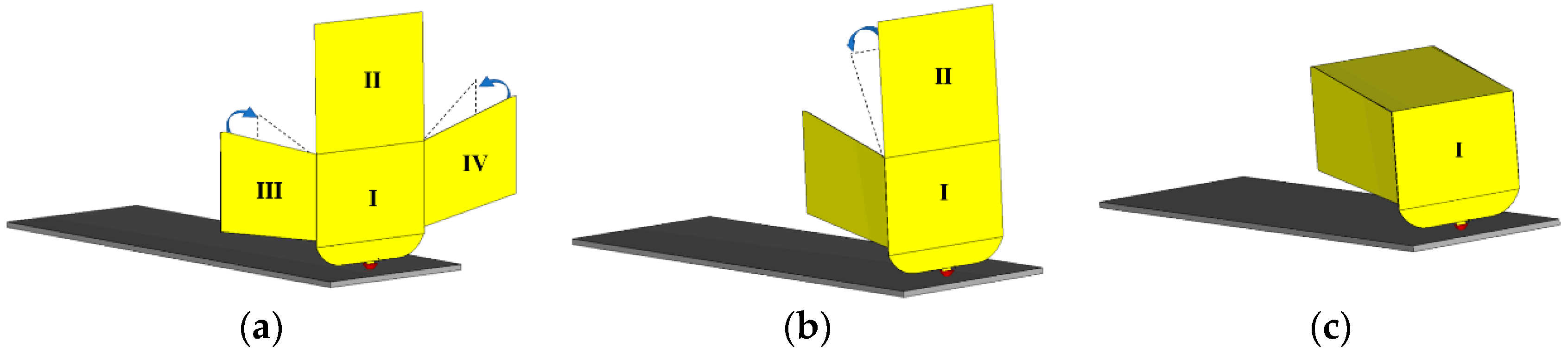
2.1. Design Steps of the Compact and Wideband Antenna Obtained from a Thin Metal Sheet

The proposed antenna was designed to be integrated under the vehicle’s dashboard. In such a position, more space can be obtained for easy integration of the antenna. Indeed, the height of the shark-fin cover on the roof is subjected to international regulations, and for aesthetic reasons the shark-fin cover should be as small as possible. A typical volume available under the shark-fin cover is 53 mm × 50 mm × 40 mm (height × length × width). To exploit the entire internal volume, a 3D antenna can be realized by cutting and folding a metal sheet instead of printed 2D antennas being used, but coexistence with other radiating elements may still be difficult.
In order to explain the operating principle of the proposed dashboard antenna, three steps have been considered (Figure 2). Initially, a three-branch monopole-like antenna was designed (Figure 2a) that provides three main resonances at 750 MHz, 1750 MHz and 2500 MHz. The antenna has its own ground plane with a size of 145 × 45 mm2. The size of the PCB represents a trade-off between electromagnetic antenna performance (a monopole antenna needs a large ground plane to avoid feeding unbalance) and mechanical integration (the available space inside the dashboard is limited by the presence of other components).
In Figure 3, the reflection coefficients of each antenna design step are plotted. As shown in Figure 2a, the monopole can be divided in four sections (I to IV). The second antenna design step was obtained by folding the two side sections, i.e., III and IV (Figure 2b). Consequently, the two resonances at 1750 MHz and 2500 MHz were shifted toward higher frequencies, while other new resonances were generated thanks to inductive and capacitive couplings between the sections. Then, to reduce the overall height and make the antenna more compact and low-profile, the straight monopole was halved and section II was folded from the vertical to the horizontal. This led to a wider −10 dB bandwidth of the antenna from around 805 MHz to 4000 MHz, as shown in Figure 2c. The antenna is fed at the bottom of the monopole element. An optimization of the monopole dimensions and shape was performed, and the final layout is shown in Figure 4, together with its final dimensions. The dimensions of the proposed antenna (first configuration) are listed in Table 1. All geometries are designed and simulated with the full wave electromagnetic software CST Microwave studio [31]. The simulated reflection coefficient of the final layout is plotted in Figure 3.

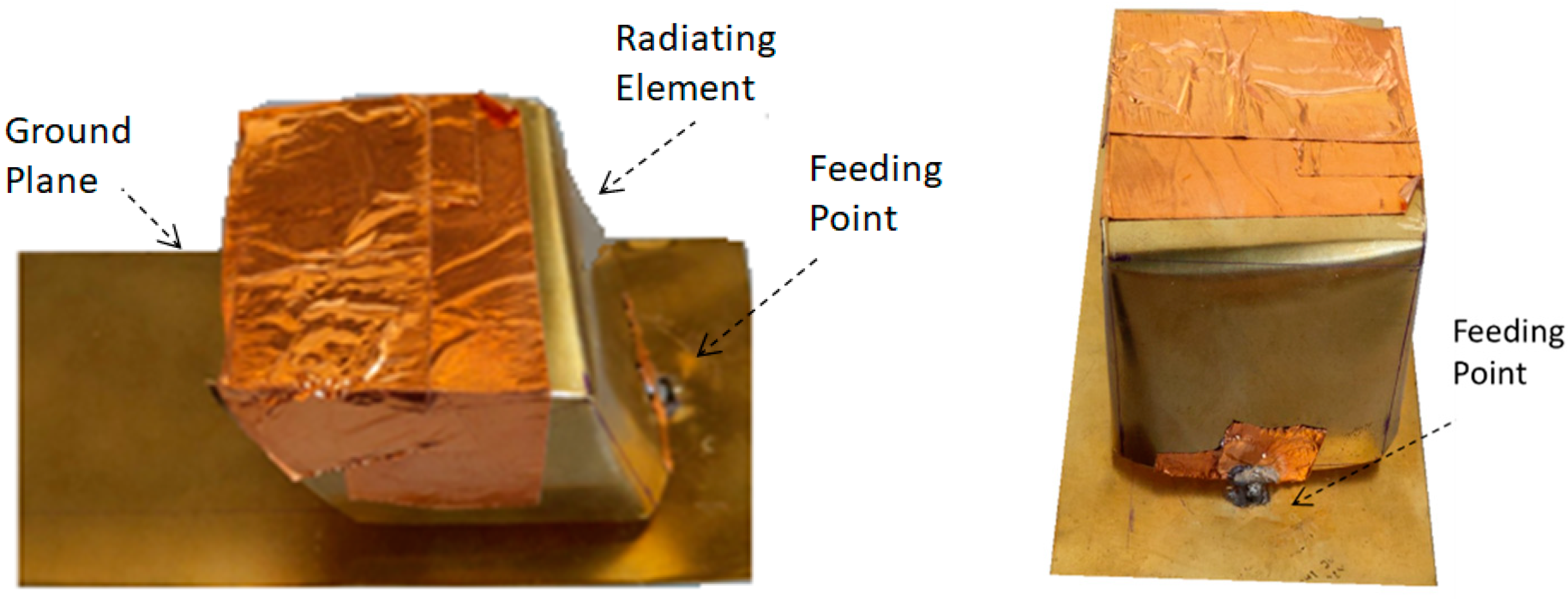
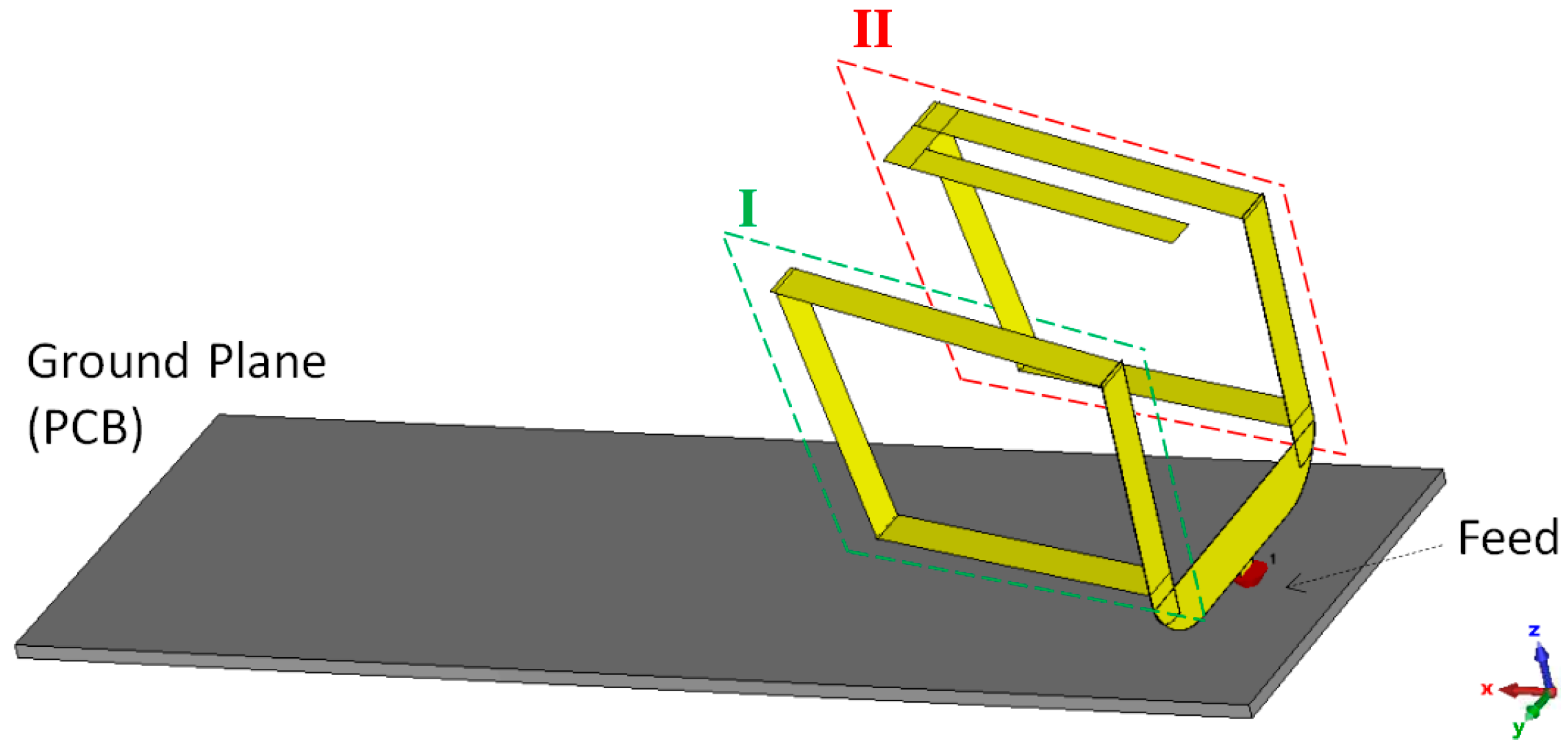
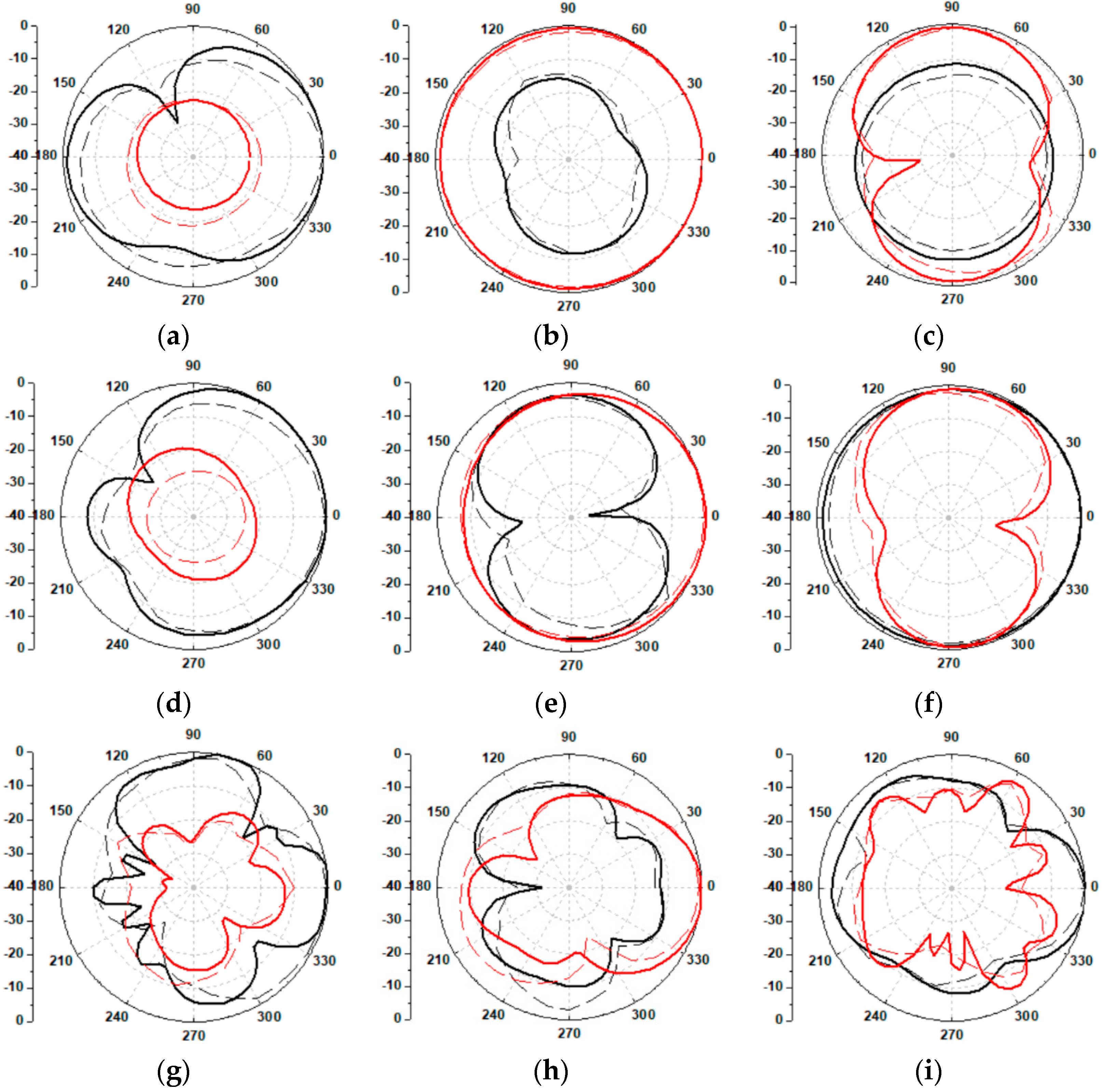
2.2. Simulated and Experimental Results

In Figure 5, a picture of the fabricated antenna prototype is shown. The proposed antenna has been measured using a Vector Network Analyzer (Keysight P937A). The measured reflection coefficient is plotted in Figure 6 and compared with that obtained with the full-wave analysis. The measured and simulated reflection coefficients were in good agreement. A small discrepancy in results is due to imperfections in the fabrication process.
Although the structure is realized with a thin (0.2 mm) metal sheet, it might be difficult to achieve the mechanical stability of the 35.5 × 40 × 45 mm3 structure. Indeed, antennas on a vehicle may be subjected to huge vibrations during vehicle movement, so that soldered parts of bulky and heavy antennas may be broken. Moreover, the integration with other radiating elements may be difficult with such geometry. For these reasons, the antenna weight was further reduced by reducing the metal sheet. The new layout is shown in Figure 7.
To better explain its operating principle, the antenna is divided into two parts, denoted as sections I and II in Figure 7. The lengths of both sections are different to obtain two separate resonances and cover the low LTE band (frequency below 1 GHz). Section II is responsible for a lower resonance frequency (around 775 MHz) compared to that of Section I (around 845 MHz). The difference in length of both sections is 32 mm, which corresponds to a shift of 70 MHz in resonance. Further increase in the length of section II led to a degradation of the input impedance matching to around 1850 GHz, which is a desired band.
Thus, to cover the LTE700 band, a small stub of with a length of 27 mm was introduced into the structure. The short-circuited stub is connected to the central part of the monopole antenna, as depicted in Figure 8a. A short and thin stub connected to the ground represents a shunt inductor. Together with the capacitive nature of electrically small and folded monopoles, it introduces a further resonance at low frequencies. Specifically, a resonance close to 700 MHz is obtained, and a good input impedance matching is obtained from 670 to 775 MHz. It is worth noting that the presence of the stub has two advantages. Firstly, a resonance at low-LTE band frequencies can be obtained without increasing overall antenna size. Secondly, the stub provides mechanical stability to the proposed structure, which is even lighter than the previous one (thin metal strips with a width of 5 mm were used). The dimensions of the proposed LTE/5G antenna (second configuration) are listed in Table 2. A photograph of the fabricated antenna prototype is shown in Figure 8b. Simulated and measured reflection coefficients of the antenna are plotted in Figure 9 considering two different cases, namely, with and without the stub.
From Figure 9b, it can be observed that the antenna with the stub has a lower resonance and that it covers LTE700 band with a good reflection coefficient (S11 < −10 dB). The discrepancy in the measured and simulated results is due to manufacturing imperfections. After validating the antenna resonance, the radiation characteristics of the antenna have been measured in an anechoic chamber using a standard double-ridged guide horn antenna (ETS-Lindgren’s model 3115) as a transmitter and the proposed antenna as a receiver. Normalized 2D radiation patterns in three different planes (xz-, yz- and xy-plane) are plotted in Figure 10. Peak realized gain is measured at various frequencies and compared to that obtained with full-wave analysis (Figure 11), resulting in a good agreement. It is worth noting that there is an almost 2 dB enhancement of gain at low frequency, while negligible variation can be observed in the remaining frequency band by introducing a shunt stub.
Comparison of the proposed work with earlier reported structures is made and listed in Table 3. Various wideband antennas were presented to cover different cellular services. Most of the entries in Table 2 are 3D antennas. In general, although printed antennas occupy less volume in a system, they suffer from poor efficiency at high frequencies due to substrate losses and they have fewer degrees of freedom for optimization. The antenna reported in [6] is a printed antenna. It supports various wireless services but it has poor radiation efficiency at the low-frequency band (698–960 MHz) due to the small electrical size. The antenna reported in [19] is a highly efficient antenna but it is too big in size and it is impossible to fit it under a shark-fin cover or inside a car’s dashboard. The antennas presented in [21,22] are size-compatible with the volume under the shark-fin cover but they cover only few services due to their multiband behavior. Two wideband antennas have been presented in [25] but each has a relatively low gain. Wideband antennas covering almost the full 617–5000 MHz band were realized in [26,27] but they cannot be fitted under shark-fin covers due to their large sizes. It is worth noting that the antenna in [27] is designed to cover the entire 617–5000 MHz band but with a maximum Voltage Standing Wave Ratio of 3.3 (return loss higher than 5.6 dB). The antenna proposed here is compact in size and can be easily integrated inside the car’s dashboard (the antenna volume is 40 mm × 40 mm × 35 mm). The proposed antenna is mechanically robust and cannot be easily damaged by vibrations during braking or vehicle movement.

3. Conclusions

A novel, wideband, low-profile, 3D automotive antenna for Long-Term Evolution (LTE) and 5G applications has been proposed in this paper. Since the number of wireless applications is rapidly increasing in vehicular and automotive systems, there is a need for new spaces for accommodating both the radiating elements and electronic circuitry. In this study, a wideband and compact 3D antenna for Long-Term Evolution (LTE) and 5G applications has been designed to be integrated under the vehicle’s dashboard. The radiating element is made from a metal sheet by properly cutting and folding it to guarantee satisfactory performance in terms of input impedance matching as well as gain. Input impedance matching at the low LTE frequency band (e.g., 617–670 MHz) can be obtained by means of a shunt stub, which also gives robustness to the structure, which is subjected to vibration during vehicle movement.

Author Contributions

Conceptualization, methodology, software validation, data curation, writing—review and editing: A.M. and R.K.S. Supervision: P.N. All authors have read and agreed to the published version of the manuscript.

Funding

This research received no external funding.

Conflicts of Interest

The authors declare no conflict of interest.

References

  1. Zamberlan, D.; Pannozzo, M. Potential implications and road mapping of satellite bidirectional S-band antennas in the automotive market. IEEE Antennas Propag. Mag. 2014, 56, 240–250. [Google Scholar]
  2. Arumugam, S.; Manoharan, S.; Palaniswamy, S.K.; Kumar, S. Design and Performance Analysis of a Compact Quad-Element UWB MIMO Antenna for Automotive Communications. Electronics 2021, 10, 2184. [Google Scholar] [CrossRef]
  3. Rütschlin, M.; Tallini, D. Simulation for antenna design and placement in vehicles. In Proceedings of the Antennas, Propagation & RF Technology for Transport and Autonomous Platforms, Birmingham, UK, 2 February 2017; pp. 1–5. [Google Scholar]
  4. Gallo, M.; Bruni, S.; Zamberlan, D. Design and measurement of automotive antennas for C2C applications. In Proceedings of the 6th European Conference on Antennas and Propagation (EUCAP), Prague, Czech Republic, 1 June 2012; pp. 1799–1803. [Google Scholar]
  5. Navarro-Méndez, D.V.; Carrera-Suárez, L.F.; Antonino-Daviu, E.; Ferrando-Bataller, M.; Baquero-Escudero, M.; Gallo, M.; Zamberlan, D. Compact wideband Vivaldi monopole for LTE mobile communications. IEEE Antennas Wireless Propag. Lett. 2015, 14, 1068–1071. [Google Scholar] [CrossRef]
  6. Ghafari, E.; Fuchs, A.; Eblenkamp, D.; Aloi, D.N. A vehicular rooftop, shark-fin, multiband antenna for the GPS/LTE/cellular/DSRC systems. In Proceedings of the IEEE-APS Topical Conference on Antennas and Propagation in Wireless Communications (APWC), Palm Beach, Aruba, 3–9 August 2014; pp. 237–240. [Google Scholar]
  7. Michel, A.; Nepa, P.; Gallo, M.; Moro, I.; Filisan, A.P.; Zamberlan, D. Printed Wideband Antenna for LTE-Band Automotive Applications. IEEE Antennas Wirel. Propag. Lett. 2017, 16, 1245–1248. [Google Scholar] [CrossRef]
  8. Wong, K.; Huang, C. Triple-Wideband Open-Slot Antenna for the LTE Metal-Framed Tablet device. IEEE Trans. Antennas Propag. 2015, 63, 5966–5971. [Google Scholar] [CrossRef]
  9. Chung, M.-A.; Yang, C.-W. Miniaturized Broadband-Multiband Planar Monopole Antenna in Autonomous Vehicles Communication System Device. Electronics 2021, 10, 2715. [Google Scholar] [CrossRef]
  10. Guan, N.; Tayama, H.; Ueyama, M.; Yoshijima, Y.; Chiba, H. A roof automobile module for LTE-MIMO antennas. In Proceedings of the IEEE-APS Topical Conference on Antennas and Propagation in Wireless Communications (APWC), Turin, Italy, 7–11 September 2015; pp. 387–391. [Google Scholar]
  11. Leelaratne, R.; Langley, R. Multiband PIFA vehicle telematics antennas. IEEE Trans. Veh. Technol. 2005, 54, 477–485. [Google Scholar] [CrossRef]
  12. Cerretelli, M.; Tesi, V.; Gentili, G. Design of a shape-constrained dual-band polygonal monopole for car roof mounting. IEEE Trans. Veh. Technol. 2008, 57, 1398–1403. [Google Scholar] [CrossRef]
  13. Izquierdo, B.S.; Jun, S.; Heirons, J.; Acharya, N. Inkjet printed and folded LTE antenna for vehicular application. In Proceedings of the 46th European Microwave Conference (EuMC), London, UK, 4–6 October 2016; pp. 88–91. [Google Scholar]
  14. Friedrich, A.; Geck, B.; Klemp, O.; Kellermann, H. On the design of a 3D LTE antenna for automotive applications based on MID technology. In Proceedings of the 2013 European Microwave Conference, Nuremberg, Germany, 6–10 October 2013; pp. 640–643. [Google Scholar]
  15. Kaddour, A.S.; Bories, S.; Bellion, A.; Delaveaud, C. 3D printed compact dual-polarized wideband antenna. In Proceedings of the 11th European Conference on Antennas and Propagation (EUCAP), Paris, France, 19–24 March 2017; pp. 3441–3443. [Google Scholar]
  16. Trong, N.N.; Piotrowski, A.; Kaufmann, T.; Fumeaux, C. Low-Profile Wideband Monopolar UHF Antennas for Integration onto Vehicles and Helmets. IEEE Trans. Antennas Propag. 2016, 64, 2562–2568. [Google Scholar] [CrossRef]
  17. Goncharova, I.; Lindenmeier, S. A High Efficient 3D Nefer Antenna for LTE Communication on a Car. In Proceedings of the 8th European Conference on Antenna and Propagation (EuCAP), The Hague, The Netherlands, 6–11 April 2014; pp. 3273–3277. [Google Scholar]
  18. Franchina, V.; Michel, A.; Nepa, P.; Parolari, R.; Moro, I.; Filisan, A.P.; Zamberlan, D. A 3D LTE antenna for vehicular applications. In Proceedings of the IEEE International Symposium on Antennas and Propagation & USNC/URSI National Radio Science Meeting, San Diego, CA, USA, 9–14 July 2017; pp. 637–638. [Google Scholar]
  19. Li, M.; Behdad, N. A Compact, Capacitively Fed UWB Antenna with Monopole-Like Radiation Characteristics. IEEE Trans. Antennas Propag. 2017, 65, 1026–1037. [Google Scholar] [CrossRef]
  20. Wang, D.; Wen, G.; Rao, Q.; Pecen, M. A 3D compact pent- band antenna for wireless mobile communication. In Proceedings of the 2008 IEEE Antennas and Propagation Society International Symposium, San Diego, CA, USA, 5–11 July 2008; pp. 1–4. [Google Scholar]
  21. Kwon, O.Y.; Song, R.; Kim, B.S. A Fully Integrated Shark-Fin Antenna for MIMO-LTE, GPS, WLAN, and WAVE Applications. IEEE Antennas Wirel. Propag. Lett. 2018, 17, 600–603. [Google Scholar] [CrossRef]
  22. Goncharova, I.; Lindenmeier, S. A high efficient automotive roof antenna concept for LTE, DAB-L, GNSS and SDARS with low mutual coupling. In Proceedings of the 9th European Conference on Antennas and Propagation (EuCAP), Lisbon, Portugal, 13–17 April 2015; pp. 1–5. [Google Scholar]
  23. Kammerer, J.; Lindenmeier, S. A new compact antenna combination with high efficiency for reception of SDARS- and GPS signals. In Proceedings of the IEEE International Symposium on Antennas and Propagation, Chicago, IL, USA, 8–14 July 2012; pp. 1–2. [Google Scholar]
  24. Franchina, V.; Michel, A.; Nepa, P.; Gallo, M.; Parolari, R.; Filisan, A.P.; Zamberlan, D. A compact 3D antenna for automotive LTE MIMO applications. In Proceedings of the 2017 IEEE-APS Topical Conference on Antennas and Propagation in Wireless Communications (APWC), Verona, Italy, 11–15 September 2017; pp. 326–329. [Google Scholar]
  25. Melli, F.; Lenzini, S.; Cerretelli, M.; Coscelli, E.; Notari, A.; Selleri, S.; Vincetti, L. Low Profile Wideband 3D Antenna for Roof-Top LTE Vehicular Applications. In Proceedings of the 2019 IEEE-APS Topical Conference on Antennas and Propagation in Wireless Communications (APWC), Granada, Spain, 9–13 September 2019; pp. 157–159. [Google Scholar]
  26. Hastürkoğlu, S.; Almarashli, M.; Lindenmeier, S. A Compact Wideband Terrestial MIMO-Antenna Set for 4G, 5G, WLAN and V2X and Evaluation of its LTE-Performance in an Urban Region. In Proceedings of the 13th European Conference on Antennas and Propagation (EuCAP), Krakow, Poland, 31 March–5 April 2019; pp. 1–5. [Google Scholar]
  27. Khalifa, M.O.; Yacoub, A.M.; Aloi, D.N. A Multiwideband Compact Antenna Design for Vehicular Sub-6 GHz 5G Wireless Systems. IEEE Trans. Antennas Propag. 2021, 69, 8136–8142. [Google Scholar] [CrossRef]
  28. Nasr, A.; Sarabandi, K.; Takla, M. Multi-beam Dual-Polarized Windshield Antenna with Wide Elevation Coverage for 5G V2X Applications. In Proceedings of the IEEE International Symposium on Antennas and Propagation and North American Radio Science Meeting, Montreal, QC, Canada, 5–10 July 2020; pp. 1333–1334. [Google Scholar]
  29. Artner, G.; Langwieser, R.; Mecklenbräuker, C.F. Concealed CFRP Vehicle Chassis Antenna Cavity. IEEE Antennas Wirel. Propag. Lett. 2017, 16, 1415–1418. [Google Scholar] [CrossRef]
  30. Artner, G.; Kotterman, W.; Galdo, G.D.; Hein, M.A. Conformal Automotive Roof-Top Antenna Cavity with Increased Coverage to Vulnerable Road Users. IEEE Antennas Wirel. Propag. Lett. 2018, 17, 2399–2403. [Google Scholar] [CrossRef]
  31. CST Studio Suite. Available online: https://www.3ds.com/products-services/simulia/products/cst-studio-suite/ (accessed on 20 June 2022).
Figure 1. Two- or three-dimensional antennas can be accommodated in several positions on a vehicle, for example, on bumpers, inside lateral mirrors, under the car’s dashboard, on the windshield or rear window, under shark-fin covers on the car roof or in cavities etched from the car roof itself.
Electronics 11 01923 g001
Figure 2. Design steps of the proposed compact and wideband antenna (first configuration): (a) step 1: the structure is cut from a rectangular metal sheet and divided into four sections, named I, II, III and IV, and the feed is connected at the bottom; (b) step 2: the side arms are folded; (c) step 3: the top section is folded and a compact monopole antenna is realized.
Electronics 11 01923 g002
Figure 3. Reflection coefficients of different geometries realized in Figure 2.
Electronics 11 01923 g003
Figure 4. Geometry of the proposed compact and wideband antenna.
Electronics 11 01923 g004
Figure 5. Photographs of the antenna prototype.
Electronics 11 01923 g005
Figure 6. Simulated and measured reflection coefficients of the antenna.
Electronics 11 01923 g006
Figure 7. Geometry explaining the design concept of a low-profile, compact and wideband antenna.
Electronics 11 01923 g007
Figure 8. Proposed low-profile, compact and wideband antenna (second configuration): (a) geometry; (b) photograph.
Electronics 11 01923 g008
Figure 9. Simulated and measured reflection coefficients (a) without and (b) with stub.
Electronics 11 01923 g009
Figure 10. Simulated (solid lines) and measured (dashed lines) normalized 2D radiation patterns: (a) xz-plane, (b) yz-plane and (c) xy-plane at 900 MHz; (d) xz-plane, (e) yz-plane and (f) xy-plane at 1500 MHz; (g) xz-plane, (h) yz-plane and (i) xy-plane at 4500 MHz. Both the θ-component (black color) and the φ-component (red curve) are plotted.
Electronics 11 01923 g010
Figure 11. Simulated and measured peak realized gain of the configuration with and without stub.
Electronics 11 01923 g011
Table 1. Dimensions of the proposed antenna (first configuration).
ParameterValue (mm)ParameterValue (mm)
H45LG143.5
L134.6W40
L235.3WG47
L328.1
Table 2. Dimensions of the proposed antenna (second configuration).
ParameterValue (mm)ParameterValue (mm)
H35L512
L40L612.5
L135.8L730
L229.1t5
L335W40
L427
Table 3. Comparison of the performance of the reported reconfigurable structures.
Operating Frequency Bands (MHz)Total EfficiencyPeak Gain in Operating Bands (dBi)Total Size (mm3)Technique UsedAntenna Type
[6]698–960, 1700–2700, 5100–6000>10% (698–960 MHz),
>80% (1700–2700 MHz),
>70% (5100–6000 MHz)
Not given37.6 × 40 × 0.8Shorted monopolePrinted
[9]2000–2740, 4062–8000>85% (2000–2740 MHz),
>80% (4062–8000 MHz)
>2.7 (2000–2740 MHz)
>2.6 * (4062–8000 MHz)
50 × 10 × 0.8MonopolePrinted
[19]576–2985>85%>2.0Diameter is 62.6 mm and height is 39 mmMonopole3D
[21]850, 1575, 2400, 5900>30.7%Not given59.5 × 44.3 × 21Planar inverted-F3D
[22]698–960, 1427–270068%2.8 (900 MHz),
4.8 (1700 MHz)
55 × 33 × 10Monopole3D
[25]700–960, 1700–2700Not given−4.5 * (850 MHz),
−0.3 * (1700 MHz)
Not givenMonopole3D
[26]700–6000>−1.5 dBNot given70 × 70 × 29Wideband Nefer monopole3D
[27]617–5000>62%Linear Average Gain > 0 dB15 × 39.8 × 60Monopole3D
This work (second configuration)617–5000>62% (670–960 MHz),
>75% (1410–1550 MHz)
>82% (1710–5000 MHz)
>−0.5 (670–960 MHz),
>1.4 (1410–1550 MHz),
>3.2 (1710–5000 MHz),
40 × 40 × 35Monopole with shunt stub3D
* Estimated from the data given in the paper.
Publisher’s Note: MDPI stays neutral with regard to jurisdictional claims in published maps and institutional affiliations.

