
Dual-Band 6 × 6 MIMO Antenna System for Glasses Applications Compatible with Wi-Fi 6E and 7 Wireless Communication Standards


Abstract
:1. Introduction
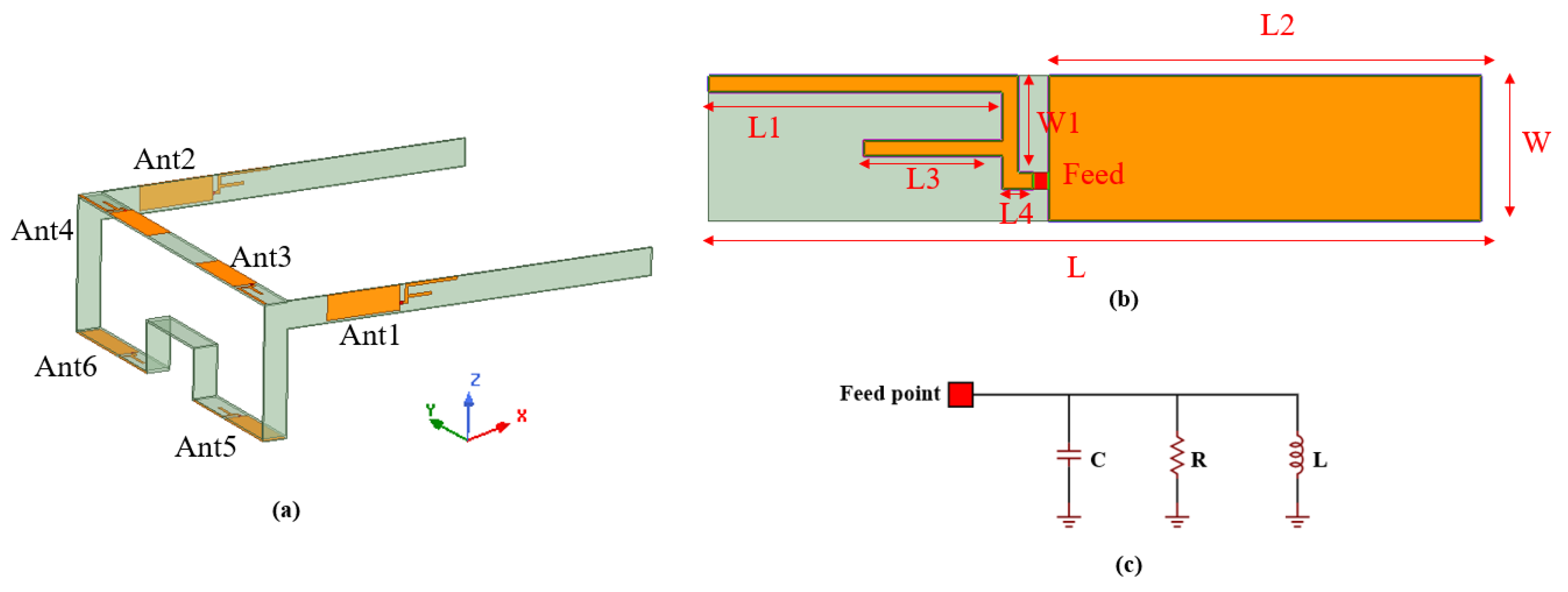
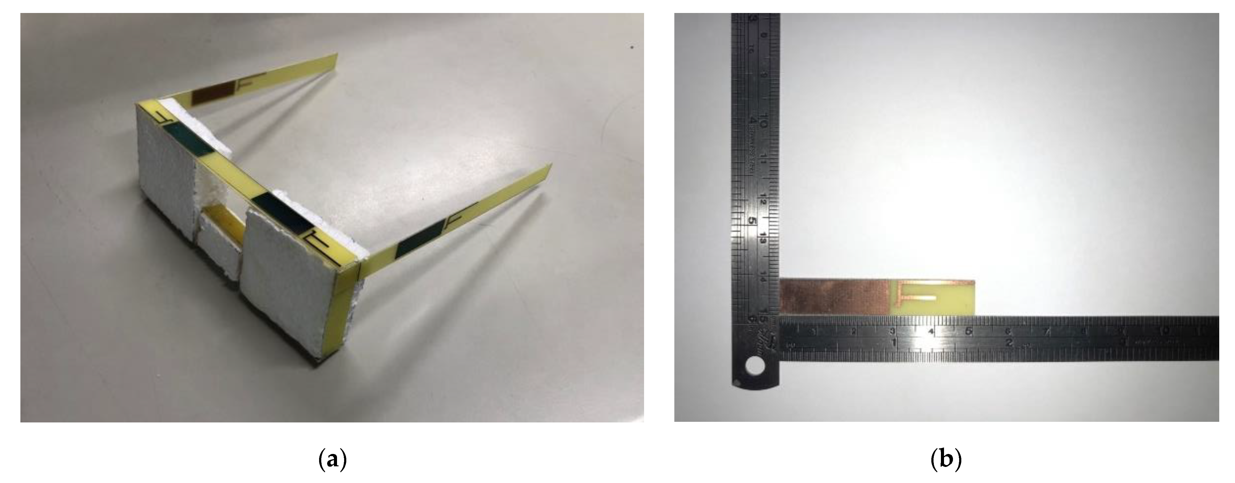
2. Design Process
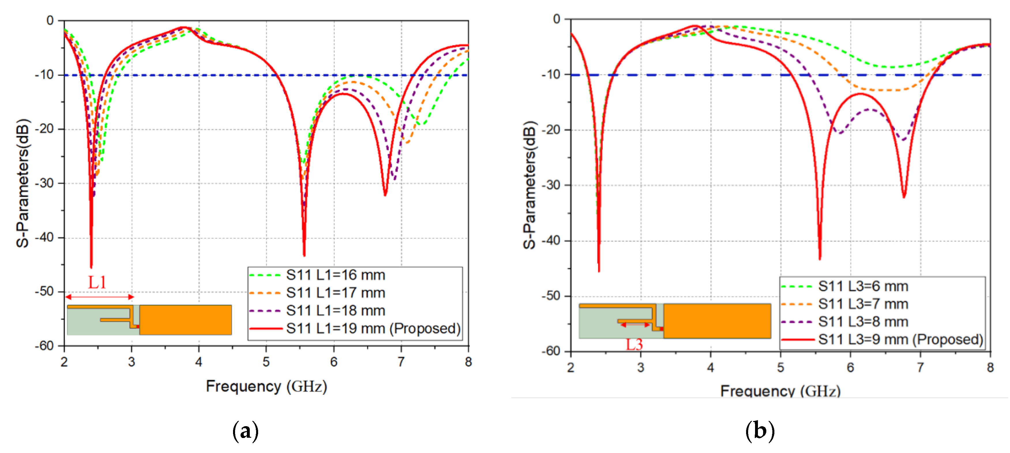
2.1. Simulation and Analysis
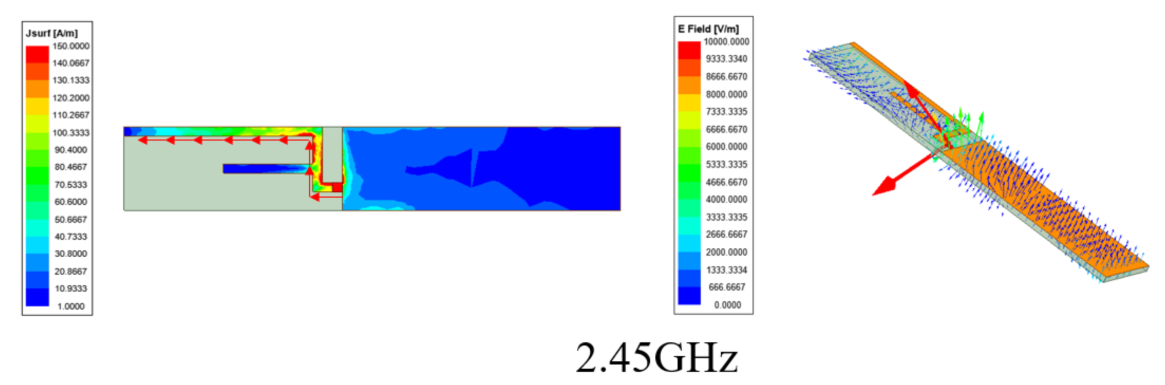
2.2. Surface Current and E Field Analysis
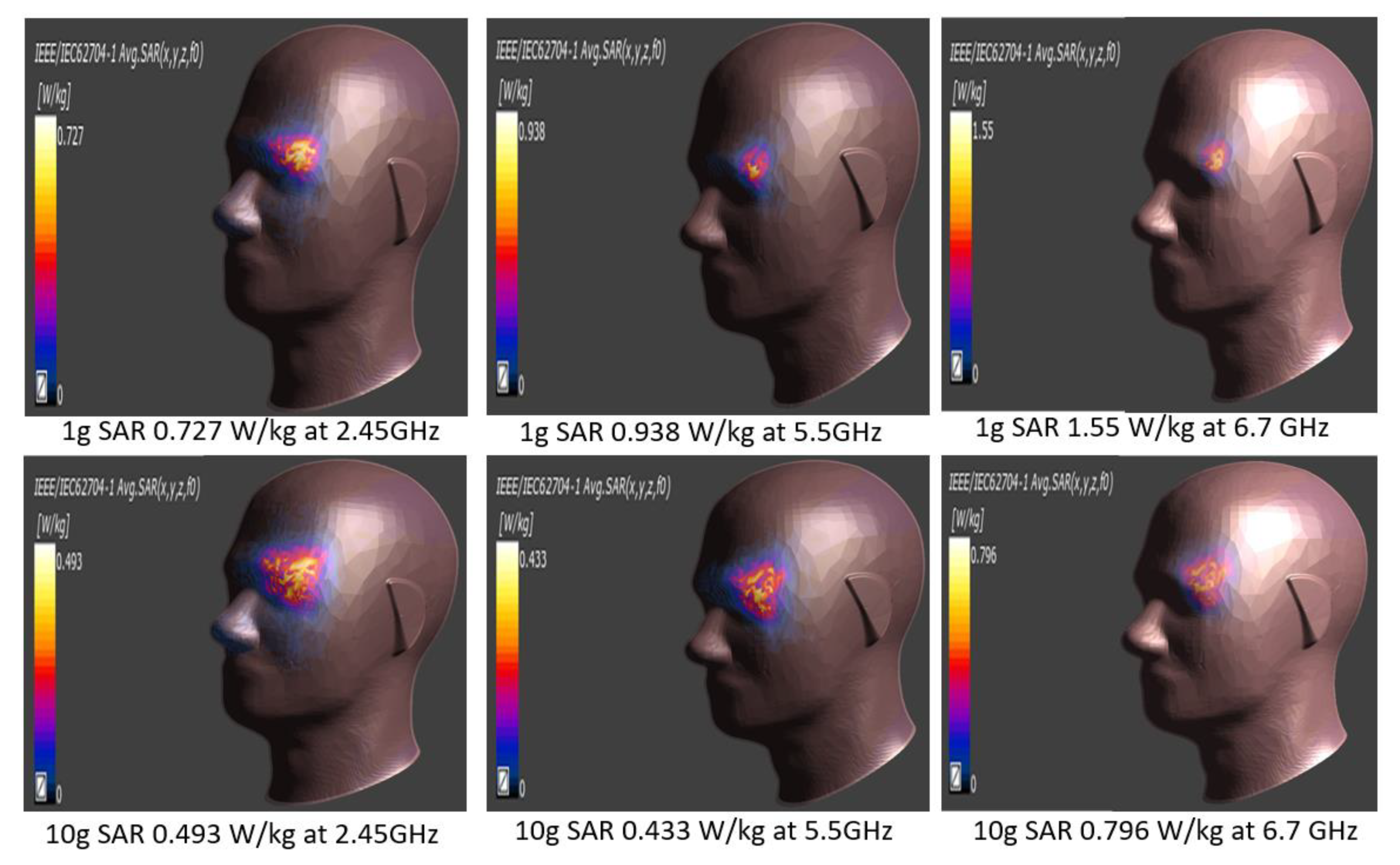
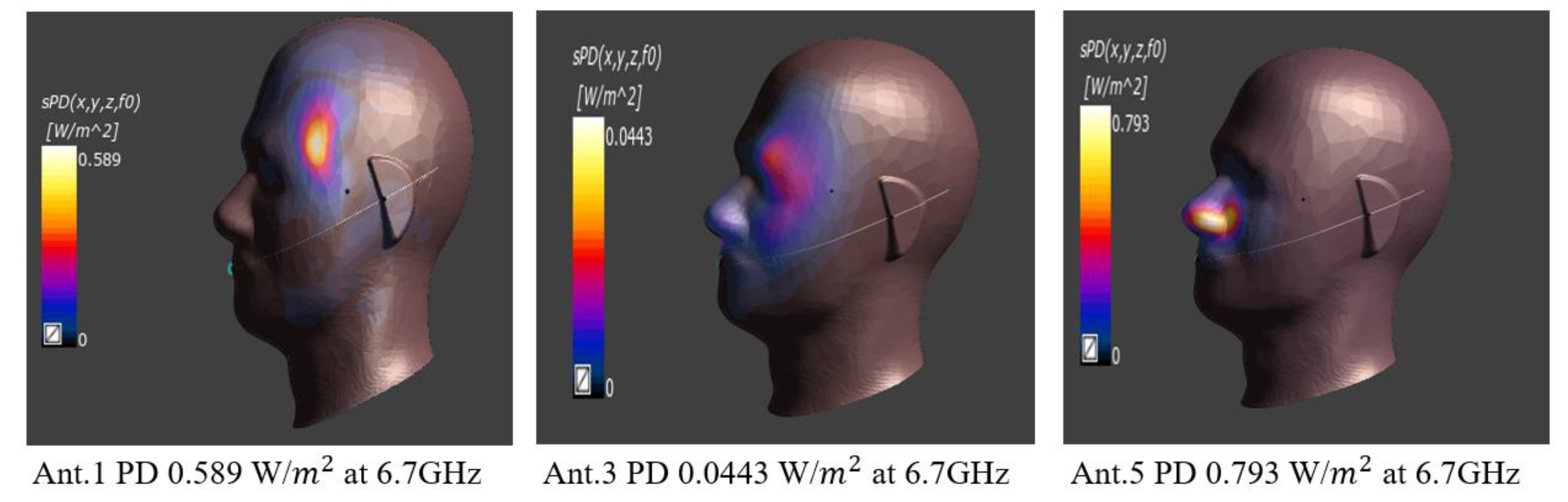
3. Human Head Simulation and Analysis
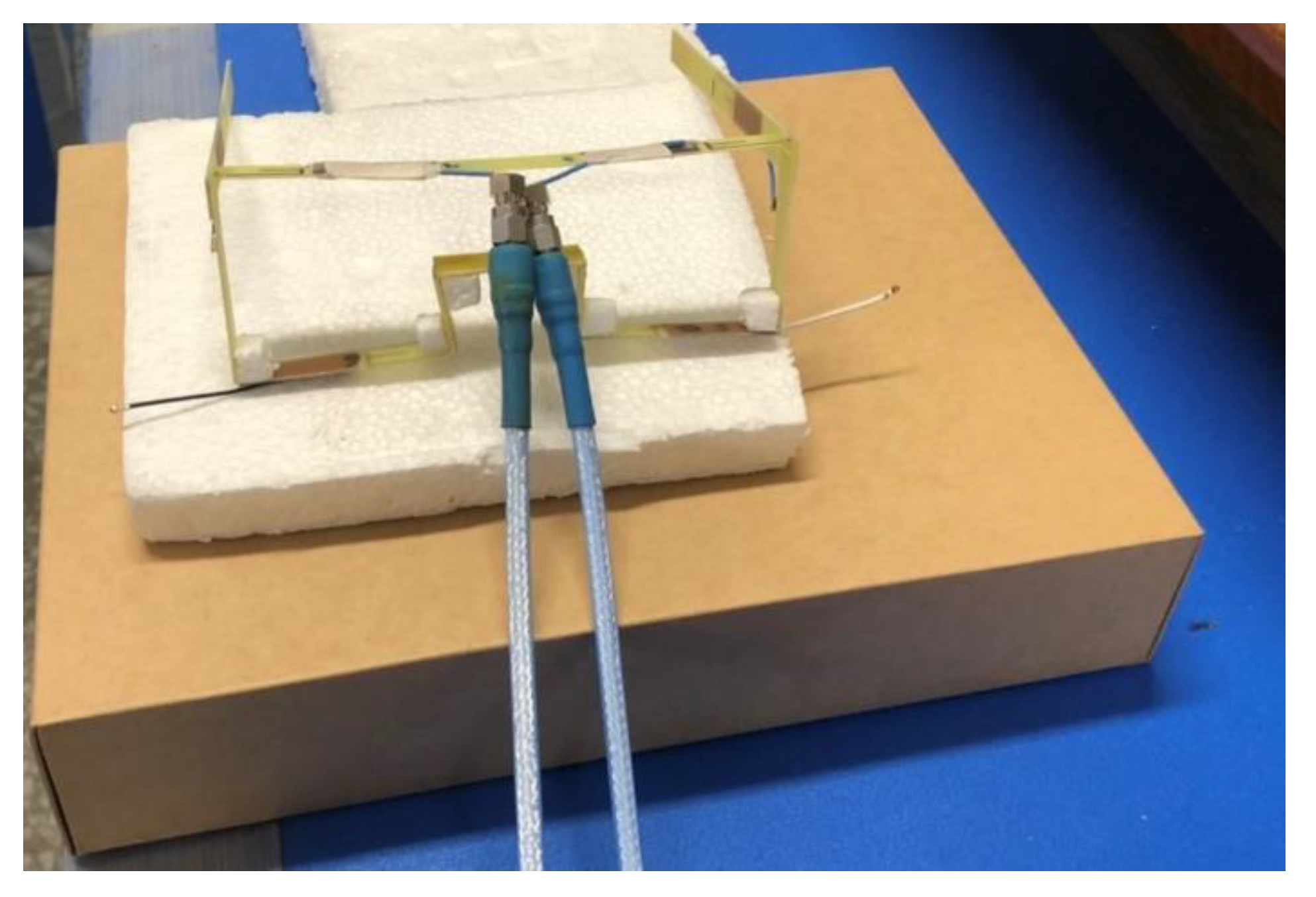
4. Measurement Results
4.1. S-Parameter Results
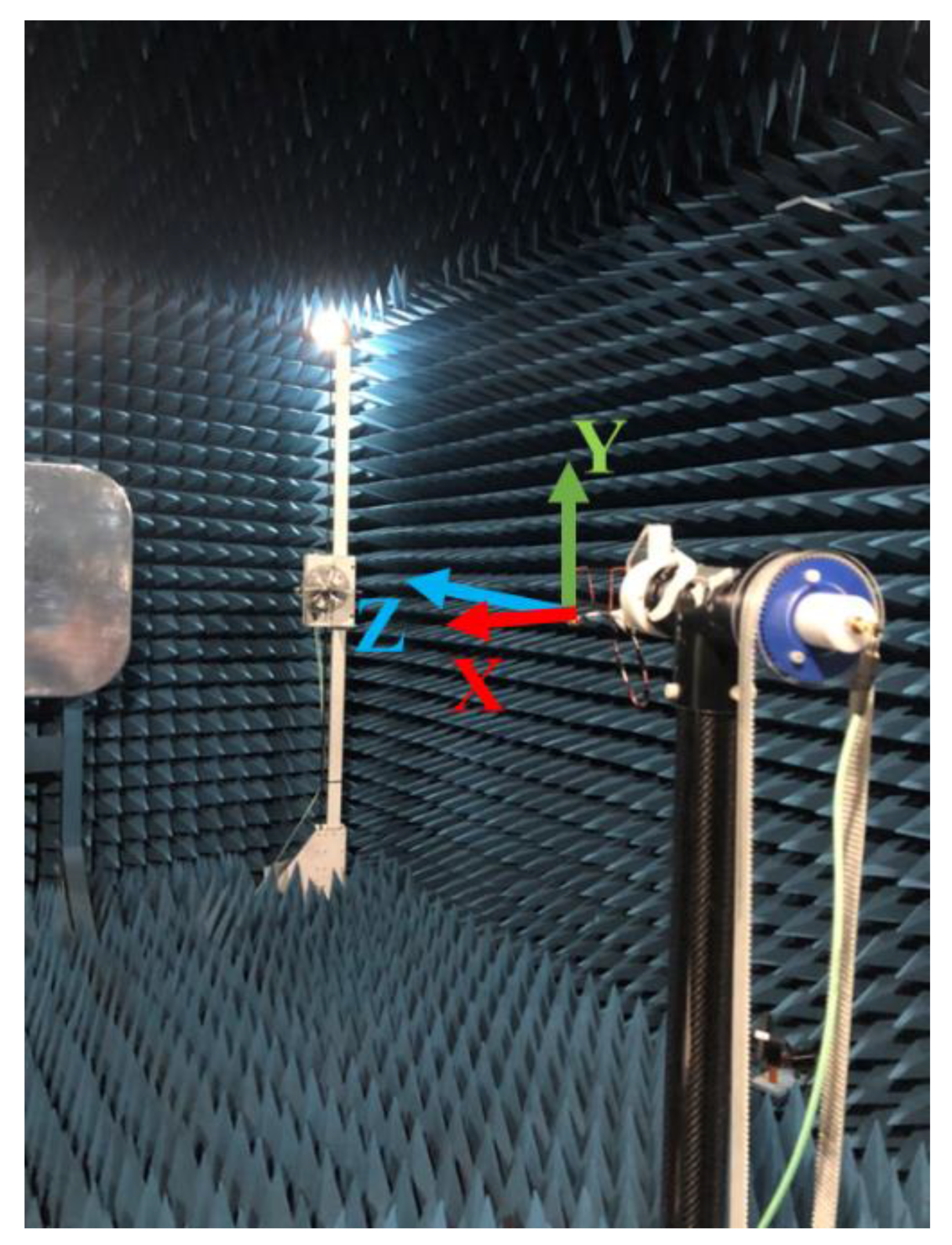
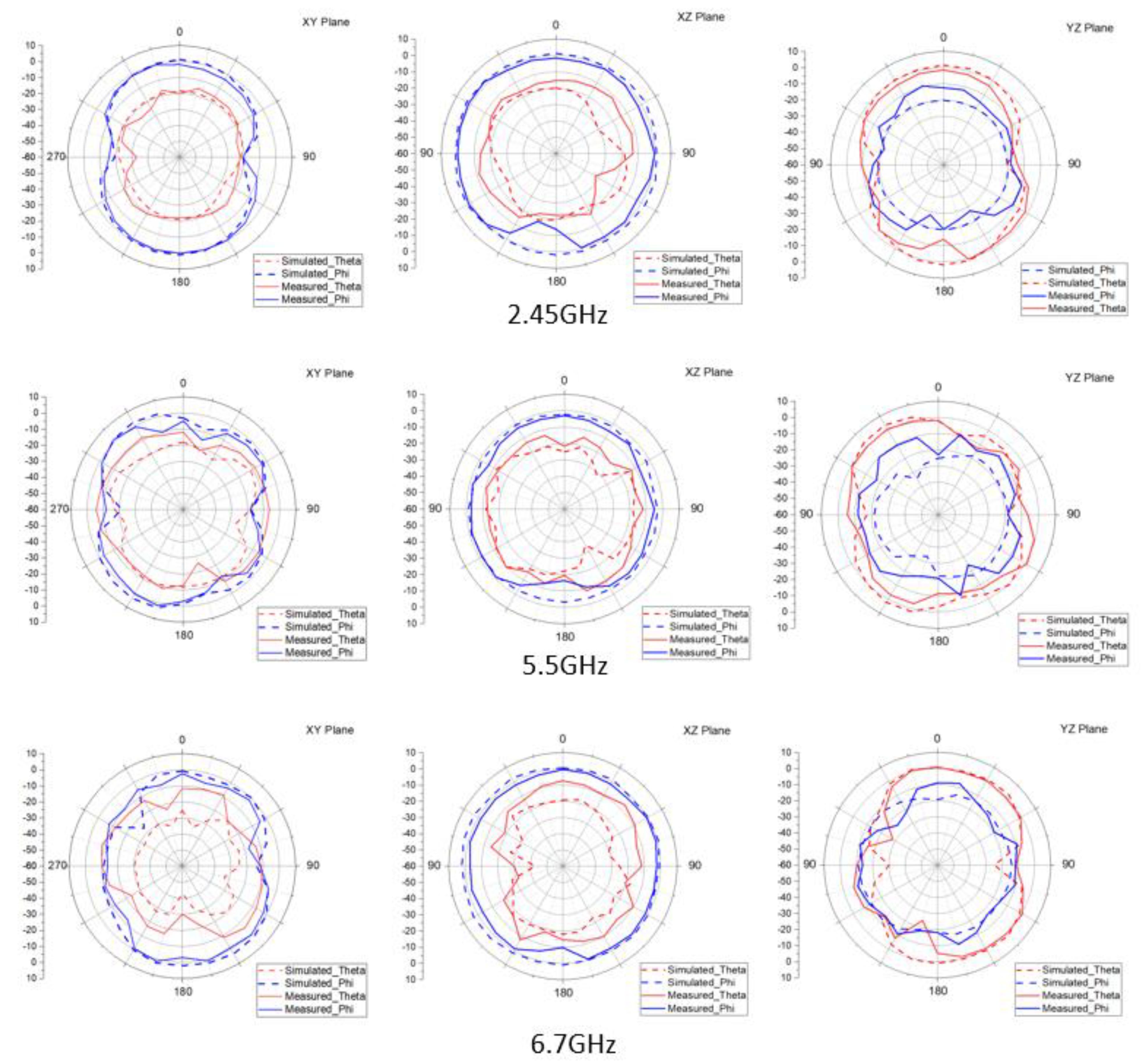
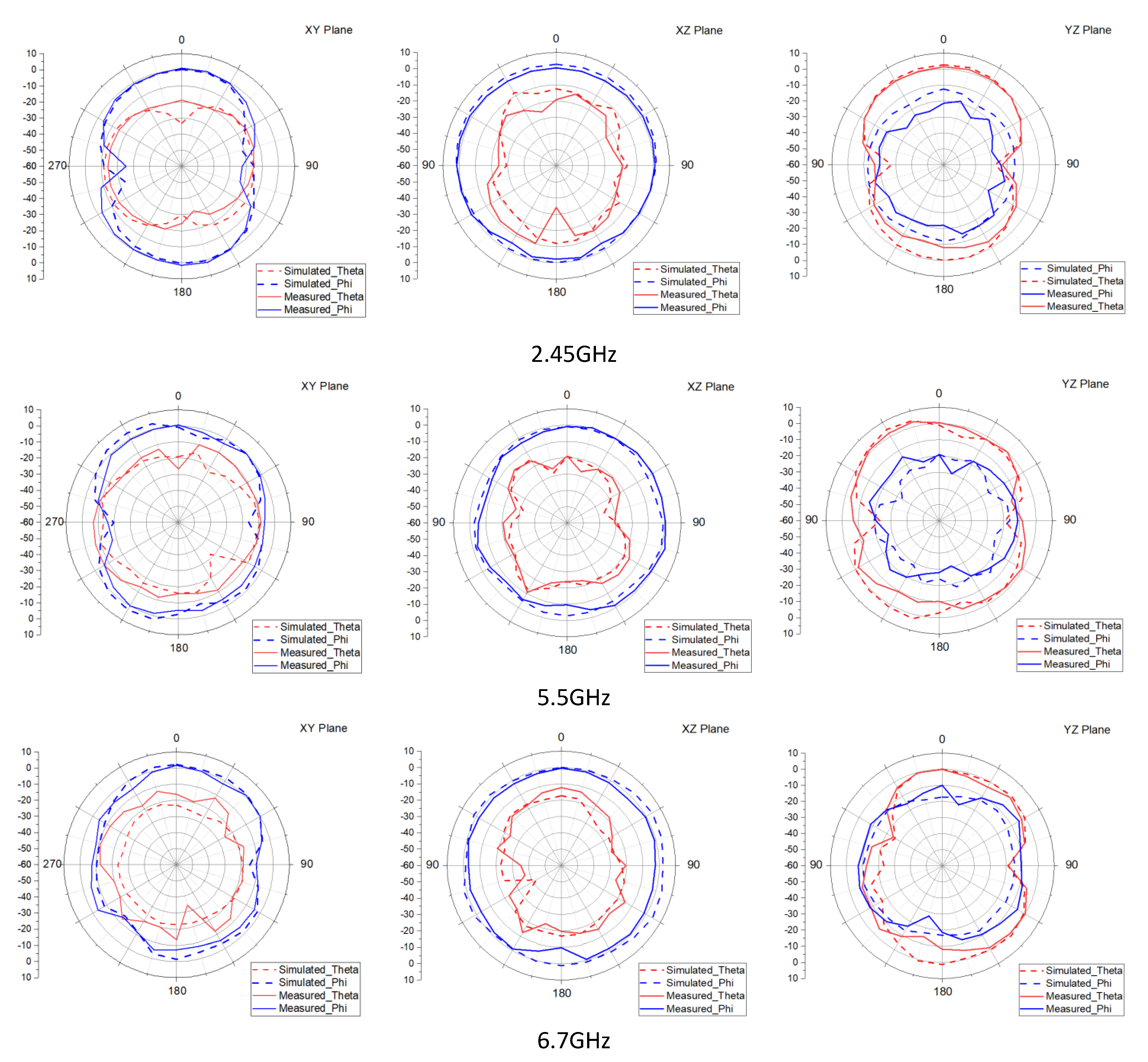
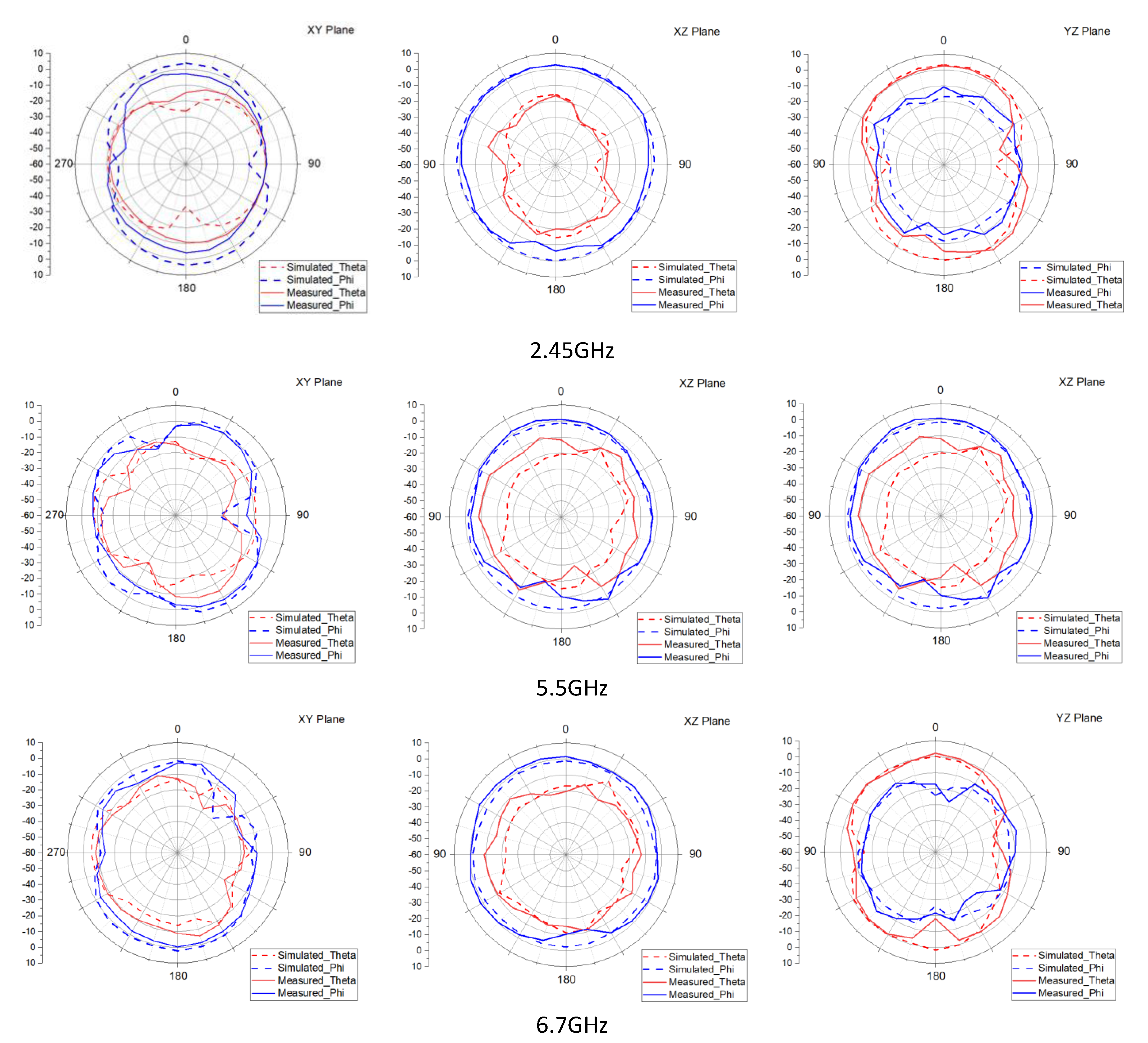
4.2. Radiation Pattern
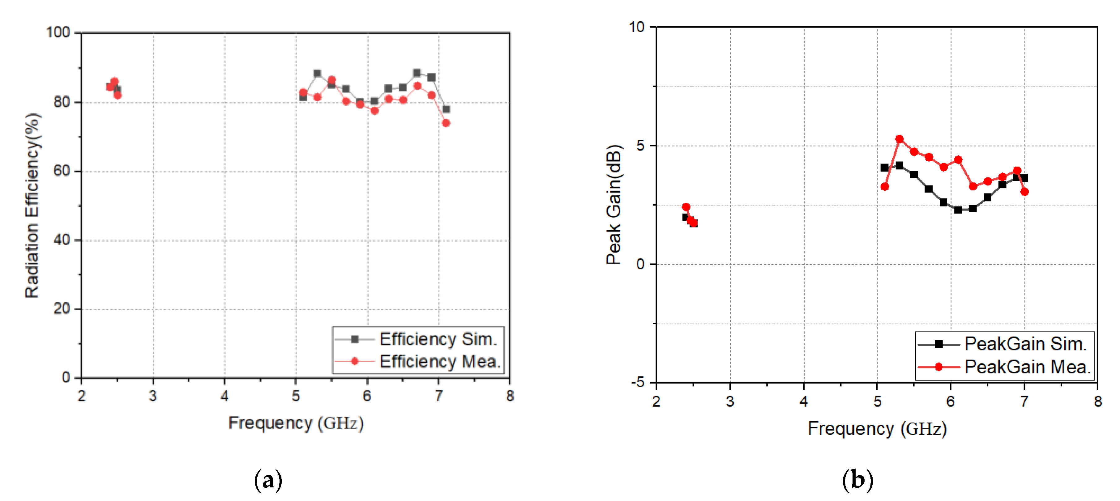
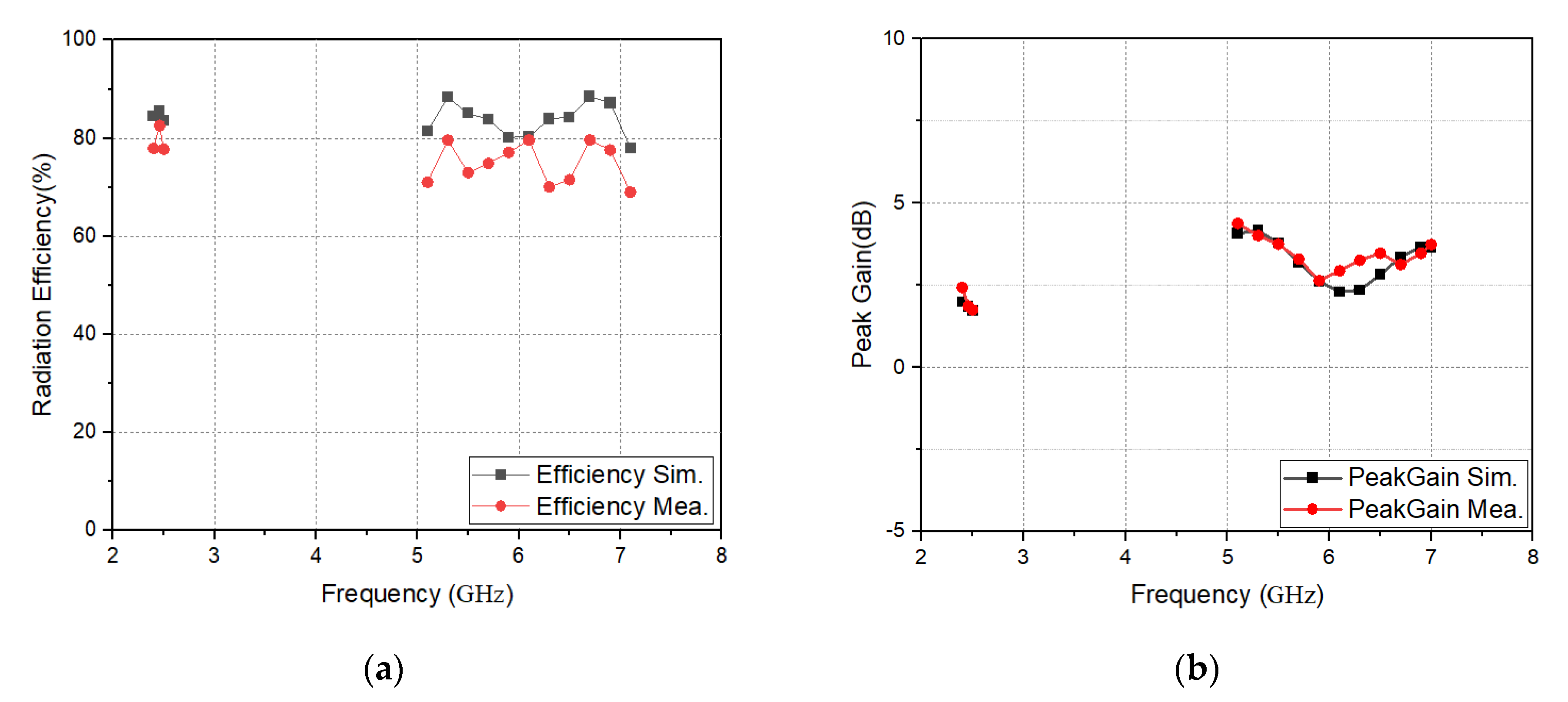
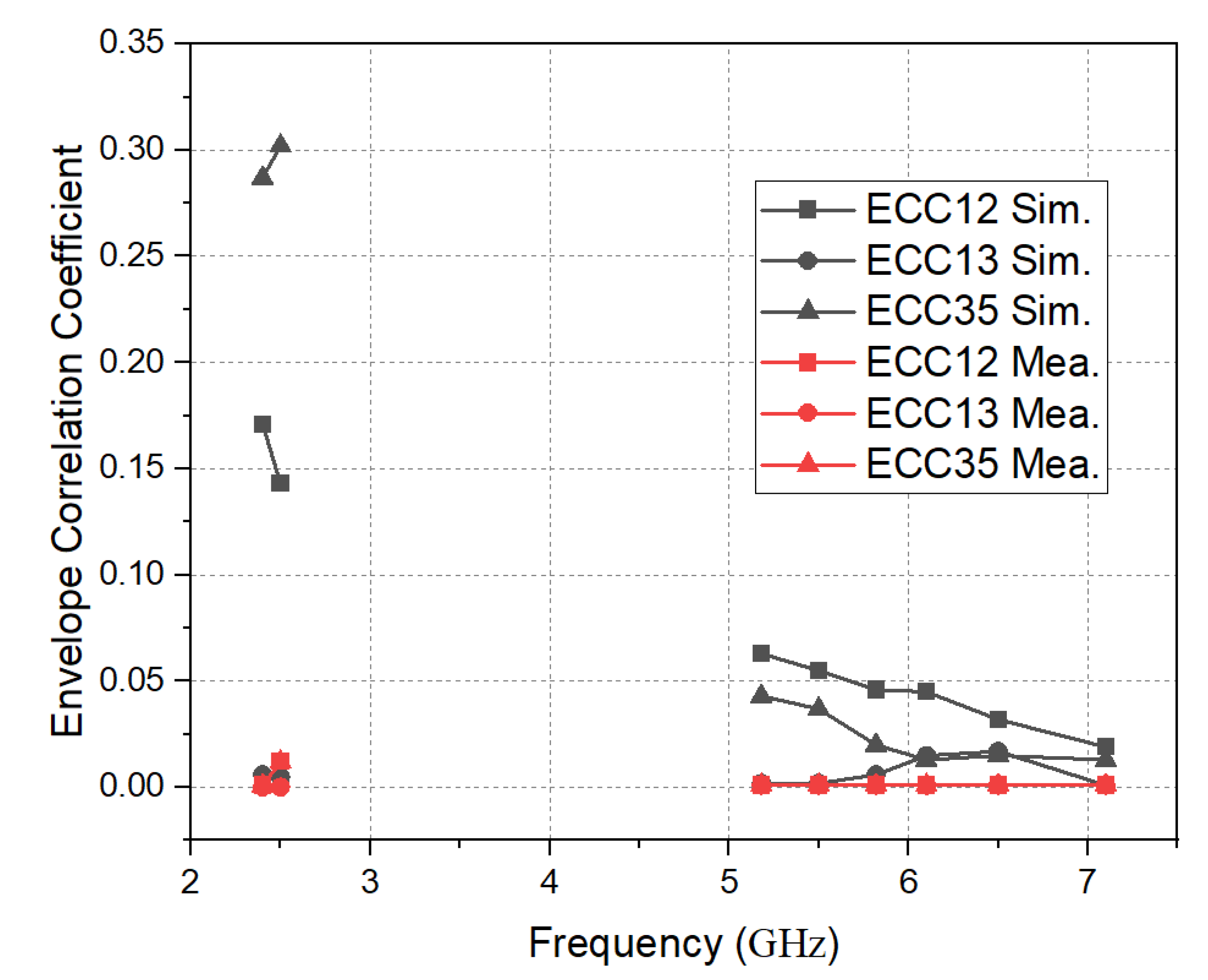
4.3. Efficiency, Gain, and ECC Results
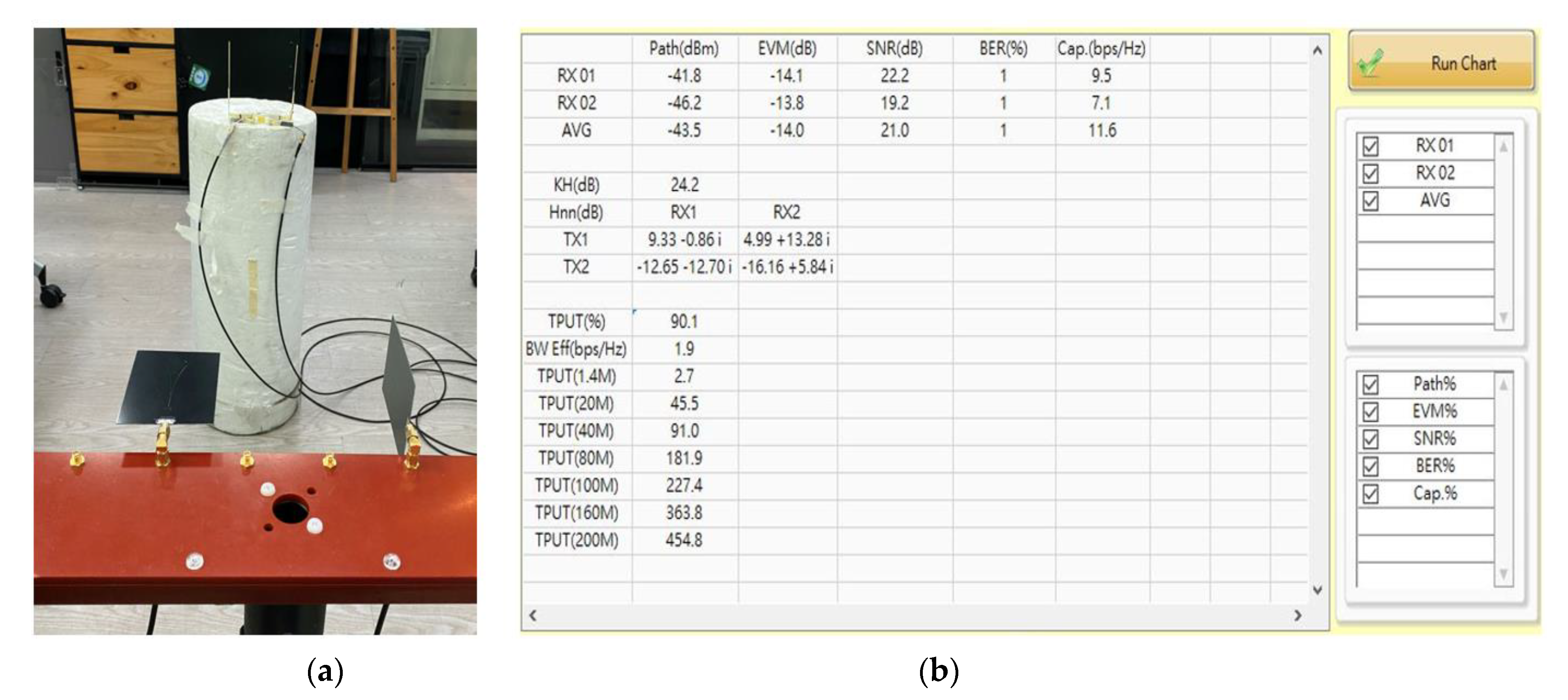
4.4. MIMO Performance
5. Conclusions
Author Contributions
Funding
Conflicts of Interest
References
- Cihangir, A.; Gianesello, F.; Luxey, C. Dual antenna concept with complementary radiation for eyewear applications. IEEE Trans. Antennas Propag. 2018, 66, 3056–3063. [Google Scholar] [CrossRef]
- Wang, Y.Y.; Ban, Y.L.; Liu, Y. Sub-6GHz 4G/5G conformal glasses antennas. IEEE Access 2019, 7, 182027–182036. [Google Scholar] [CrossRef]
- Cihangir, A.; Panagamuwa, C.J.; Whittow, W.G.; Jacquemod, G.; Gianesello, F.; Pilard, R.; Luxey, C. Dual-band 4G eyewear antenna and sar implications. IEEE Trans. Antennas Propag. 2017, 65, 2085–2089. [Google Scholar] [CrossRef] [Green Version]
- Hu, X.; Yan, S.; Zhang, J.; Volskiy, V.; Vandenbosch, G.A.E. Omni-directional circularly polarized button antenna for 5 GHz WBAN applications. IEEE Trans. Antennas Propag. 2021, 69, 5054–5059. [Google Scholar] [CrossRef]
- Le, T.T.; Yun, T.Y. Miniaturization of a dual-band wearable antenna for WBAN applications. IEEE Antennas Wireless Propag. Lett. 2020, 19, 1452–1456. [Google Scholar] [CrossRef]
- Shahzad, M.A.; Paracha, M.N.; Naseer, S.; Ahmad, S.; Malik, M.; Farhan, M.; Ghaffar, A.; Hussien, M.; Sharif, A.B. An artificial magnetic conductor-backed CompactWearable antenna for smart watch IoT applications. Electronics 2021, 10, 2908. [Google Scholar] [CrossRef]
- Zhong, Y.; Wen, H.; Wang, K.; Lu, X.; Liang, Q.; Jiang, Z. A dual-band monopole antenna for WLAN in application. In Proceedings of the 2017 International Applied Computational Electromagnetics Society Symposium (ACES), Suzhou, China, 1–4 August 2017. [Google Scholar]
- Chen, A.; Sun, M.; Zhang, Z.; Fu, X. Planar monopole antenna with a parasitic shorted strip for multistandard handheld terminals. IEEE Access 2020, 8, 51648–51652. [Google Scholar] [CrossRef]
- Thiruvenkadam, S.; Parthasarathy, E.; Palaniswamy, S.K.; Kumar, S.; Wang, L. Design and performance analysis of a compact planar MIMO antenna for IoT applications. Sensors 2021, 21, 7909. [Google Scholar] [CrossRef]
- Smida, A.; Iqbal, A.; Alazemi, A.J.; Waly, M.I.; Ghayoula, R.; Kim, S. Wideband wearable antenna for biomedical telemetry applications. IEEE Access 2020, 8, 15687–15694. [Google Scholar] [CrossRef]
- Ghouz, H.H.M.; Sree, M.F.A.S.; Ibrahim, M.A. Novel wideband microstrip monopole AntennaDesigns for Wi-Fi/LTE/WiMax devices. IEEE Access 2020, 8, 9532–9539. [Google Scholar] [CrossRef]
- Mathur, P.; Augustine, R.; Gopikrshna, M.; Raman, S. Dual MIMO antenna system for 5G mobile phones, 5.2 GHz WLAN, 5.5 GHz WiMAX and 5.8/6 GHz Wi-Fi applications. IEEE Access 2021, 9, 106734–106742. [Google Scholar] [CrossRef]
- Cihangir, A.; Panagamuwa, C.J.; Whittow, W.G.; Gianesello, F.; Luxey, C. Ultrabroadband antenna with robustness to body detuning for 4G eyewear devices. IEEE Antennas Wirel. Propag. Lett. 2016, 8, 1225–1228. [Google Scholar] [CrossRef]
- Chung, M.A.; Hsiao, W.C.; Yang, C.W.; Chuang, B.R. 4 × 4 MIMO antenna system for smart eyewear in Wi-Fi 5G and Wi-Fi 6E wireless communication applications. Electronics 2021, 10, 2936. [Google Scholar] [CrossRef]
- Ali, H.; Ren, X.C.; Bari, I.; Bashir, M.A.; Hashmi, A.M.; Tareen, M.A.K.; Anjum, M.R. Four-Port MIMO antenna system for 5G n79 band RF devices. Electronics 2022, 11, 35. [Google Scholar] [CrossRef]
- Cai, C.A.; Kai, K.Y.; Liao, W.J. A WLAN/WiFi-6E MIMO antenna design for handset devices. In Proceedings of the 2021 International Symposium on Antennas and Propagation, Taipei, Taiwan, 19–22 October 2021. [Google Scholar]
- Wnag, W.; Zhang, M.; Bai, Z.; Guo, H.; Tan, E.K. Wi-Fi 6E test challenges on ATE. In Proceedings of the 2021 China Semiconductor Technology International Conference (CSTIC), Shanghai, China, 14–15 March 2021. [Google Scholar]
- Cihangir, A.; Whittow, W.; Panagamuwa, C.; Jacquemod, G.; Gianesello, F.; Luxey, C. 4G antennas for wireless eyewear devices and related SAR. Comptes Rendus Phys. 2015, 16, 836–850. [Google Scholar] [CrossRef] [Green Version]
- Matthaiou, M.; Koulouridis, S.; Kotsopoulos, S. A novel dual-band implantable antenna for pancreas telemetry sensor applications. Telecom 2022, 3, 1–16. [Google Scholar] [CrossRef]
- RF Exposure Procedures and Equipment Authorization Policies for Mobile and Portable Devices. 2015. Available online: https://apps.fcc.gov/oetcf/kdb/forms/FTSSearchResultPage.cfm?switch=P&id=20676 (accessed on 23 October 2015).
- IEEE Recommended Practice for Determining the Peak Spatial-Average Specific Absorption Rate (SAR) in the Human Head from Wireless Communications Devices: Measurement Techniques. Available online: https://ieeexplore.ieee.org/document/6589093 (accessed on 6 September 2013).
- FCC Wi-Fi 6E RF Exposure—FCC Report. 2021. Available online: https://fcc.report/FCC-ID/MSQI005D/5126834.pdf (accessed on 4 February 2021).
- Hong, S.; Kang, S.H.; Kim, Y.; Jung, C.W. Transparent and flexible antenna for wearable glasses applications. IEEE Trans. Antennas Propag. 2016, 64, 2797–2804. [Google Scholar] [CrossRef]
- Choi, S.; Choi, J. Miniaturized MIMO antenna with a high isolation for smart glasses. In Proceedings of the IEEE-APS Topical Conference on Antennas and Propagation in Wireless Communications (APWC), Verona, Italy, 11–15 September 2017. [Google Scholar]
- Wang, Y.; Zhang, J.; Peng, F.; Wu, S. A glasses frame antenna for the applications in internet of things. IEEE Internet Things J. 2019, 6, 8911–8918. [Google Scholar] [CrossRef]
- Bisognin, A.; Cihangir, A.; Luxey, C.; Jacquemod, G.; Pilard, R.; Gianesello, F.; Costa, J.R.; Fernandes, C.A.; Lima, E.B.; Panagamuwa, C.J.; et al. Ball grid array-module with integrated shaped lens for WiGig applications in eyewear devices. IEEE Trans. Antennas Propag. 2017, 65, 6380–6394. [Google Scholar] [CrossRef]
- Hong, Y.; Chou, J. 60 GHz patch antenna array with parasitic elements for smart glasses. IEEE Antennas Wirel. Propag. Lett. 2018, 17, 1252–1256. [Google Scholar] [CrossRef]


| Parameter | L | W | L1 | L2 | L3 | L4 | W1 |
|---|---|---|---|---|---|---|---|
| Units (mm) | 50 | 9 | 20 | 28 | 9 | 2 | 6 |
| WLAN Modulation | Frequency | Power | Throughput (Ant.1&2) | SNR (Ant.1&2) | Throughput (Ant.3&4) | SNR (Ant.3&4) | Throughput (Ant.5&6) | SNR (Ant.5&6) |
|---|---|---|---|---|---|---|---|---|
| 4QPSK | 2.4 GHz | 10 dB | 81.5% | 16.2 dB | 80% | 15.1 dB | 80.3% | 18 dB |
| 4QPSK | 5.5 GHz | 10 dB | 82.4% | 16.6 dB | 90.1% | 20.1 dB | 80.8% | 17.2 dB |
| Ref. | Apply to | Ant Type | Gain (dBi) | Efficiency (%) | Operating Band/BW (GHz) | MIMO |
|---|---|---|---|---|---|---|
| [1] | Glasses | Monopole and Loop | Monopole: −11.6 Loop: −2.7 | Monopole: 10.7 Loop: 33.9 | Wi-Fi 2.4G Mono: 2.32–2.35 Loop: 2.35–2.5 | 2 × 2 |
| [2] | Glasses | Loop and Slot | LB: 2.67 HB: 3.72 | LB: 86.5 HB: 98 | LTE/Sub-6G 0.82–0.96 1.71–2.69 3.3–3.6 4.8–5.0 | LTE 2 × 2 Sub-6G 4 × 4 |
| [3] | Glasses | CE | LB: −5.03 HB: 0.65 | LB: 58 HB: 63 | LTE 0.7–2.7 | NA |
| [14] | Glasses | Slot | 5.1G: 4.3 6.8G: 3.3 | 5.1G: 85.7 6.8G: 82.8 | Wi-Fi 5G/WiFi 6E 4.58–5.72 6.38–7.0 | 4 × 4 |
| [23] | Glasses | IAI | 2.4G: 3.56 | 2.4G: 46.8 | Wi-Fi 2.4G 2.4–2.5 | NA |
| [24] | Glasses | Patch | 2.45G: −1.08 | 2.45G: 23 | Wi-Fi 2.4G 2.43–2.48 | 2 × 2 |
| [25] | Glasses | Frame | 5.8G: 8.18 | NA | IOT 5.8 G 5.42–6.27 | NA |
| [26] | Glasses | Array | 60G: 11 | WiGig: 58 | WiGig 57–66 | NA |
| [27] | Glasses | Array | 60G: 9.29 | NA | 60G 59.05–60.1 | NA |
| This work | Glasses | Monopole | 2.4G: 1.9 5.5G: 4.4 6.7G: 3.7 | 2.45G: 86.1 5.5G: 86.5 6.7G: 85.4 | WiFi 2.4G /WiFi 5G/WiFi 6E 2.4~2.5 5.15~7.2 | 6 × 6 |
Publisher’s Note: MDPI stays neutral with regard to jurisdictional claims in published maps and institutional affiliations. |
© 2022 by the authors. Licensee MDPI, Basel, Switzerland. This article is an open access article distributed under the terms and conditions of the Creative Commons Attribution (CC BY) license (https://creativecommons.org/licenses/by/4.0/).
Share and Cite
Chung, M.-A.; Hsiao, C.-W. Dual-Band 6 × 6 MIMO Antenna System for Glasses Applications Compatible with Wi-Fi 6E and 7 Wireless Communication Standards. Electronics 2022, 11, 806. https://doi.org/10.3390/electronics11050806
Chung M-A, Hsiao C-W. Dual-Band 6 × 6 MIMO Antenna System for Glasses Applications Compatible with Wi-Fi 6E and 7 Wireless Communication Standards. Electronics. 2022; 11(5):806. https://doi.org/10.3390/electronics11050806
Chicago/Turabian StyleChung, Ming-An, and Cheng-Wei Hsiao. 2022. "Dual-Band 6 × 6 MIMO Antenna System for Glasses Applications Compatible with Wi-Fi 6E and 7 Wireless Communication Standards" Electronics 11, no. 5: 806. https://doi.org/10.3390/electronics11050806
APA StyleChung, M.-A., & Hsiao, C.-W. (2022). Dual-Band 6 × 6 MIMO Antenna System for Glasses Applications Compatible with Wi-Fi 6E and 7 Wireless Communication Standards. Electronics, 11(5), 806. https://doi.org/10.3390/electronics11050806