Article

Implementation of an Electronically Based Active Power Filter Associated with a Digital Controller for Harmonics Elimination and Power Factor Correction

1
Electrical Engineering Department, Faculty of Engineering, Kafrelsheikh University, Kafrelsheikh 33516, Egypt
2
Electrical Engineering Department, Faculty of Engineering, Fayoum University, Fayoum 43518, Egypt
3
Department of Information Technology, College of Computer and Information Sciences, Princess Nourah bint Abdulrahman University, P.O. Box 84428, Riyadh 11671, Saudi Arabia
4
Electronics Engineering and Electrical Communication Department, Higher Institute of Engineering and Technology, Kafrelsheikh 33516, Egypt
*
Authors to whom correspondence should be addressed.
Electronics 2022, 11(14), 2205; https://doi.org/10.3390/electronics11142205
Submission received: 18 June 2022 / Revised: 11 July 2022 / Accepted: 12 July 2022 / Published: 14 July 2022
(This article belongs to the Section Power Electronics)

Abstract

:
This paper introduces simulation study and hardware implementation of a shunt active power filter (SAPF). The SAPF is considered an effective method for improving power quality by enhancing the power factor and reducing the total harmonic distortion (THD) for power sources due to nonlinear loads. A digital notch filter is used for extracting the reference current signal. The hysteresis band current controller is used to generate gating switching signals that control the switches of SAPF. The proposed model is constructed using Simulink/MATLAB environment and Proteus VMS, and the performance of the model is tested through a simulation study. The model of SAPF with a digital notch-filter is implemented using the Arduino microcontroller and a printed circuit board (PCB) layout. The model emulating a single-phase SAPF prototype is built and tested in the University of Kafrelshiekh, Faculty of Engineering laboratory. Significant improvements in power quality issues confirm the ability and effectiveness of SAPF, as well as reducing THD to a level less than 5%, which is in proportion to IEEE Std. 519-1992 and IEEE Std. 519-2014. The results emphasize the importance of SAPF to mitigate harmonics problems and enhance power factors.

1. Introduction

Rapid development in the power electronics domain has resulted in significant impacts in many applications, where harmonic currents are injected into the utility system by power electronic loads [1,2]. The dependence of a large amount of equipment on this affects the power quality due to the presence of harmonics in the network voltages and currents. Malfunctions of electronic equipment in operation such as (electronic household appliances, medical equipment, solid-state controls, etc.), vibration and pulsating torque of rotating machines, loss of a large amount of power in the distribution, dielectric stress of transformers and also problems of interference in communication systems are among the problems resulting from the presence of harmonics [3]. The operation failure of user equipment can be caused by any problem obvious in voltage, current or frequency; this is defined as power quality in an EPRI power quality workbook. Power quality is defined as power supply characteristics which are required for the proper and safe function of user equipment. Voltage sag or swell, transients, unbalance and distortions of voltage are common power quality problems. Due to these problems, the variation of power quality can be classified as variations in steady-state such as harmonic distortion and voltage flicker, transient disturbances such as law and high frequency and fundamental frequency disturbances such as under and over voltages [4].
Because of these problems affecting power quality, many researchers have sought to find and develop dynamic solutions to power quality issues, power factor correction and harmonics elimination [5,6]. The goal of harmonic researches is quantifying distortion in both current waveforms and voltage at different points within a power system. These harmonics affect the power equipment of consumers, communication systems and revenue billing and cause significant operating losses. Active filters are equipment that can compensate for current and voltage harmonics; they can be utilized in power factor correction, power quality improvement and reduction of the THD to a level compatible with different standards [7,8,9,10,11]. Passive and active filters are the two major categories of harmonic filters [12]. Passive filters use capacitors and inductors, known as passive elements, to mitigate harmonics. However, there are some serious drawbacks to these passive filters, such as they do not have flexibility, large parameter tolerance and eliminate only the harmonics of specific frequencies [4]. With the development of power electronic devices by recent advances in semiconductor technology, SAPF removes harmonics by power injection in line. They are composed of switching devices which are pulse width modulation (PWM) controlled, besides to intelligent digital controller to make harmonic sensing and generate the PWM, in addition to a source of power indicated as common coupling capacitor [13]. Shunt filters and series filters are the two major categories of APFs. Shunt filters can be regarded as sources for current harmonic. They generate a current component in the opposite direction and at the same magnitude as the harmonics contained in the source waveform [14]. However, the series filters are efficient in generating harmonic voltages that compensate for load harmonic voltages [15]. The principle of active power filter (APF) controllers relies on identifying the fundamental component in the load-current form and its harmonics content to generate the compensating component. Several methods have been introduced over the last few years, such as instantaneous P-Q theory for both single- and three-phase versions [16,17], selective harmonic control depending on multi-rotating reference frames [18], other methods utilizing generalized integrators (GIs) [19], a Fast Fourier transform (FFT) approach [20] and other solutions based on artificial intelligence [21], fuzzy logic controller [22] and neural network controllers [23]. In [24], a Model Reference Controller (MRC) was used to define the amplitude for the reference supply current for the control APF system. Single-phase shunt APF to compensate current harmonic depending on neural filtering was presented in [25]. In [26], a band current controller that is an adaptive hysteresis was introduced for APF. In [27], a PWM control with neural networks was used to control an APF. Adaptive control for an APF that makes harmonic suppression as well as power factor correction was introduced in [28]. In [29], the implementation of hybrid SAPF to improve power quality was introduced. Correction of grid harmonic current using parallel three-phase SAPF was presented in [30]. Hybrid automaton-fuzzy control to single-phase dual buck half-bridge SAPF for power quality improvement was studied in [31]. APF was proposed in linear systems for power factor correction in [32]. SAPF and thyristor-Controlled Reactor are used in [33] for harmonic reduction along with reactive power correction. SAPF using synchronous reference frame approach with a phase locked loop as well as hysteresis current controller to extract the harmonic currents is introduced in [34]. To increase the SAPF performance, several researchers have suggested techniques with different current control approaches, including linear current control, besides to current mode and an artificial intelligence method. This paper uses a hysteresis band current controller with a digital notch filter as a shunt active power filter. The current controller with a digital notch filter is adaptive to any distortion and has a dynamic behavior. This makes its performance more efficient and more flexible. The paper concerns the design and fabrication of single-phase shunt APF using a Digital Notch Filter and an Arduino microcontroller. In addition, the FFT approach is used in the Arduino microcontroller to estimate %THD and source power factor.
The main contributions for this paper can be reported as:
-
The development of an effective method to enhance power factor and reduce %THD;
-
The simulation for single-phase SAPF is achieved utilizing a MATLAB/Simulink environment;
-
The pre-test of the proposed design is achieved using Proteus VMS. The prototype is implemented using PCB boards;
-
Significant improvement in power factor is reported;
-
The results emphasize the importance of SAPF in eliminating harmonics and enhance power factor.
The organization of the rest of the current paper is described as follows: In Section 2, a description of the shunt active power filter and its controller is introduced. Additionally, the relationship between THD and power factor correction is presented in Section 2. The simulation of a single-phase SAPF using a MATLAB/Simulink environment, prototype simulation using a Proteus simulator and hardware implementation of SAPF are explained in Section 3. Section 4 concludes the main findings.

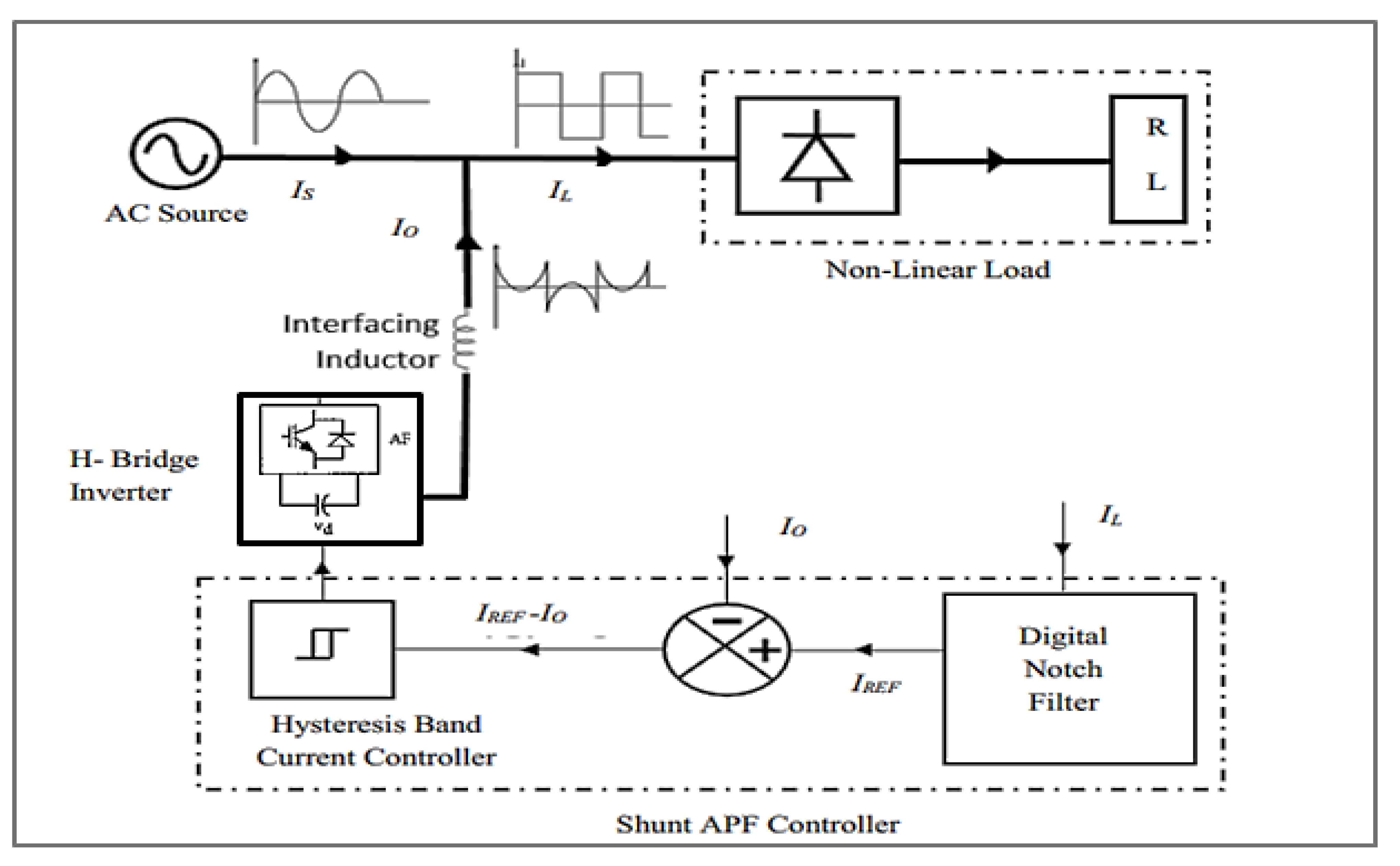
2. Description of Shunt Active Power Filter and Its Controller

The shunt active power filter is a voltage source converter-based half-bridge, full-bridge or H-bridge topology. The H-bridge topology is considered in this work. H-bridge SAPF can achieve performance that is more acceptable with less on–off frequency. In addition, the cascaded H-bridge is easy and simple to handle and maintain. The description of the proposed active power filter and its controller are explained in the following subsections.

2.1. Shunt Active Power Filter (SAPF)

The function of SAPF is to eliminate the harmonics or reduce their effect by making THD lower than the 5% level that is defined by different standards (e.g., IEEE Std. 519-1992, IEEE Std. 519-2014, IEC 61000-2-2, IEC 61000-2-4). SAPF is installed with nonlinear loads. It is recommended for commercial loads rating less than 200 kVA and less than 69 kV. Figure 1 shows the configuration of SAPF that is connected in parallel to a single-phase system between the AC source and nonlinear load. This SAPF has an ability to compensate for the current harmonics and eliminate distortion in the source waveform by generating a current component in the opposite direction and at the same magnitude as the harmonics contained in the source waveform. The injected harmonic components eliminate the source harmonics exhibited through nonlinear loads and compensate for the reactive power. To perform the function of SAPF, an effective current controller must be used.
The single-phase SAPF includes a full-bridge inverter with four IGBTs or MOSFETs switches and a DC-bus link capacitor. The voltage source inverter is connected to the system through a filtering inductor. Based on the switching gates of the inverter, the desired compensating component can be generated. The model emulates a single-phase SAPF prototype that has been built and tested in the University of Kafrelsheikh, Faculty of Engineering laboratory. A Simulink/MATLAB environment and Proteus VMS were used to facilitate the implementation of the control system with the Arduino microcontroller and PCB layout.

2.2. Control Strategy for SAPF

The control strategy for SAPF is considered the core component that realizes the correct action of the filter. The control strategy comprises three stages: sensing the current/voltage signals, extracting the compensating commands according to the filter configuration and the control method and generating the switching gate signals.
The Hall effect current/voltage sensor senses the required signals and feeds them to the microcontroller. In addition, the extracted signals are analyzed using the time-domain or frequency-domain technique to determine the compensating commands [4,35]. Fast Fourier transform is one of the most effective frequency domain techniques, while the notch filter is one of the most effective time-domain techniques, especially with the advances in digital microcontrollers [7,36].

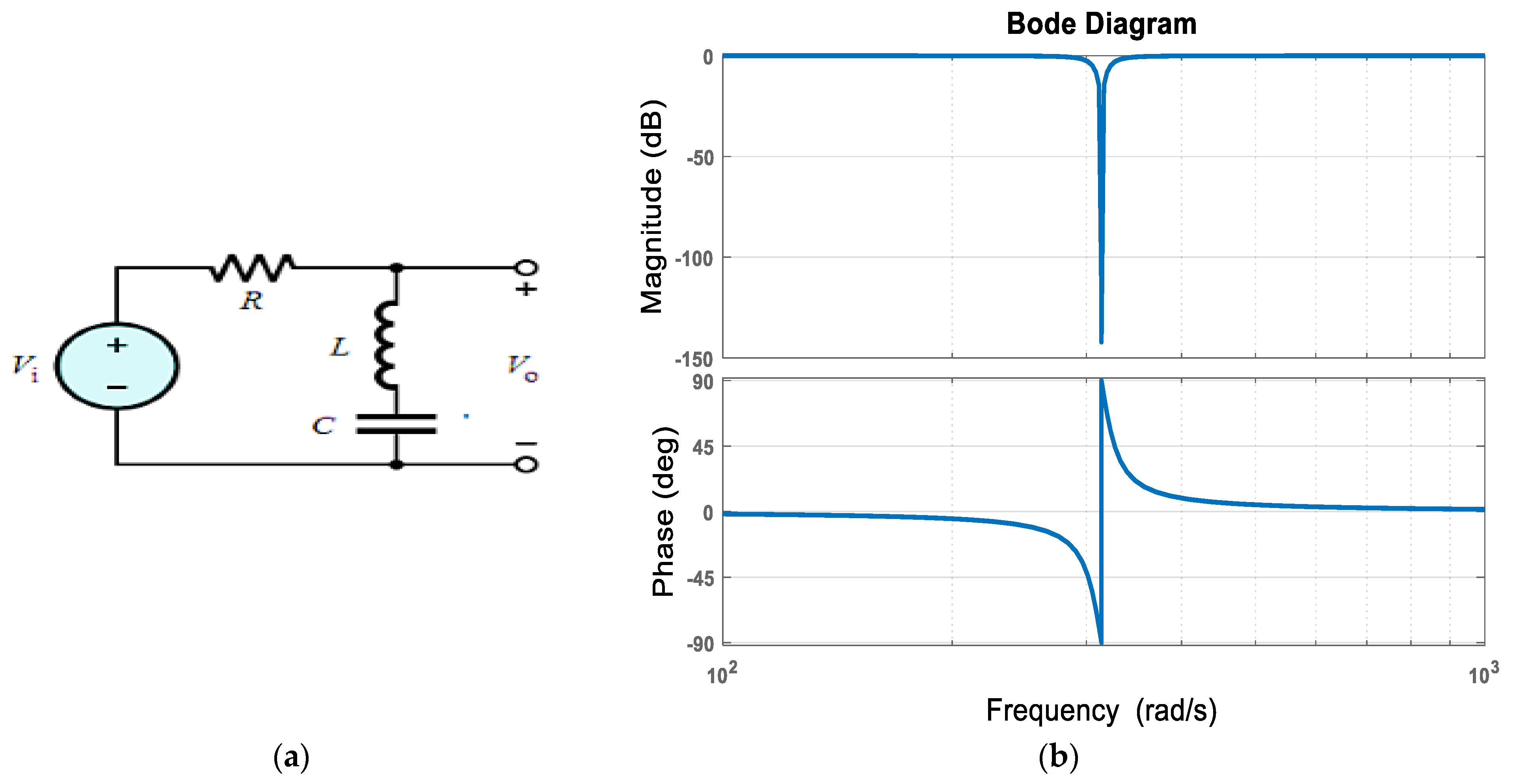
2.2.1. Extraction of Reference Current Signal Using Digital Notch Filter

The reference signal may be a current or voltage signal according to the filter configuration and the type of controller. Here, the reference signal is the current signal extracted using the digital notch filter to compensate for the current harmonics. The digital notch filter is a stop band filter that prevents a specified frequency from passing. The objective here is to stop the fundamental and extract the harmonic existing in the load current.
To employ a digital notch filter to extract the reference harmonic signal, the filter is implemented using the passive element (R, L, C). The notch filter allows all frequencies to pass except the cut-off frequency “ w c ” with a narrow notch or high-quality factor. Figure 2a shows the equivalent circuit of the passive notch filter. The impedance of the “LC” branch is zero at cut-off-frequency to make the output voltage equal to zero at this frequency. The cut-off-frequency is determined by making the value of inductive reactance equal to the capacitive reactance, which results in Equation (1).
w c = 1 / L C
The transfer function of the passive notch filter is derived mathematically at a cut-off-frequency equal to 50 Hz [35]. Mathematically, the output voltage is zero at the cut-off-frequency. The transfer function for the passive notch filter is provided as follows:
G ( s ) = V o V i = L s + 1 / C s R + L s + 1 / C s ,
G ( s ) = V o V i = L C s 2 + 1 R C s + L C s 2 + 1 .
By simplifying Equation (3) and dividing by LC, the transfer function becomes:
  G ( s ) = V o V i = s 2 + 1 / L C s 2 + R s / L + 1 / L C
G ( s ) = s 2 + w c 2 s 2 + β s + w c 2
where   β   is the bandwidth of the filter, and it relies on the value of R and L. Quality factor (Q) is provided by w c / β . Here,   w c   equals   314   rad / s , the value of β   is   25   and   a  Q- factor of 12.56 is considered for the notch filter, Figure 2b.
The bi-linear transformation of the s-domain transfer function to the z-domain is essential to converting from analog processing to digital signal processing [37]. The transformation from s-domain to z-domain can be carried out by many methods such as impulse invariant, step invariant, matched Z, bi-linear transformation, etc. The bi-linear transformation converts G(s) into G(z). Equation (6) show the relationship between the continuous and discrete function operators, ‘s’ and ‘z’, as:
s = 2 ( z 1 ) T ( z + 1 )
As in Equation (6), the convertor function depends on the sampling frequency of the converted signal, f s . The sampling time (T) is 1 / f s ,   which satisfies the Nyquist Criteria [37]. Bi-linear transformation is used to convert the signals of continuous time-analog to signals of discrete-time or digital ones with the microcontroller.
For the designed transfer function, G(s) and a sampling frequency of 5000, the bilinear of “(([1 0 314^2], [1 25 314^2]), 5000)” results in vectors of the new transfer function coefficients of the digital notch filter. These vectors are [0.9975 −1.9911 0.9975] and [1.0 −1.9911 0.9950]. Therefore, the z-domain transfer function for the digital notch filter is provided as follows:
G ( z ) = Y ( z ) X ( z ) = 0.9975 1.9911 z 1 + 0.9975 z 2 1.0 1.9911 z 1 + 0.9950 z 2 .
By simplifying G(z) to obtain the Y(z) equation and then taking the inverse of the z-transform, the digital sampling code is constructed as:
y ( k ) = 0.9975   x ( k ) 1.9911   x ( k 1 ) + 0.9975 x ( k 2 ) + 1.9911 y ( k 1 ) 0.9950 y ( k 2 )
where, k = nT, n = 0, 1, 2, 3, etc.
The general form of the discrete sampling signal, y ( k ) , depends on the notch filter design where its coefficients ( w 0 ,   w 1 w 4 ) vary with different sampling frequencies.
y ( k ) = w 0   x ( k ) w 1 x ( k 1 ) + w 2 x ( k 2 ) + w 3 y ( k 1 ) w 4 y ( k 2 ) .
A digital notch filter uses an analog to digital converter (ADC) to supply the nonlinear waveform to the microprocessor as it is programmed with the function represented by the response for the notch filter. Later, the filter output is the harmonic waveform without the fundamental. Again, a digital to analog converter (DAC) is utilized to out the processing signal. Here, the discrete digital processing signal represents the harmonic reference current, I r e f , that is used in the hysteresis band current controller.

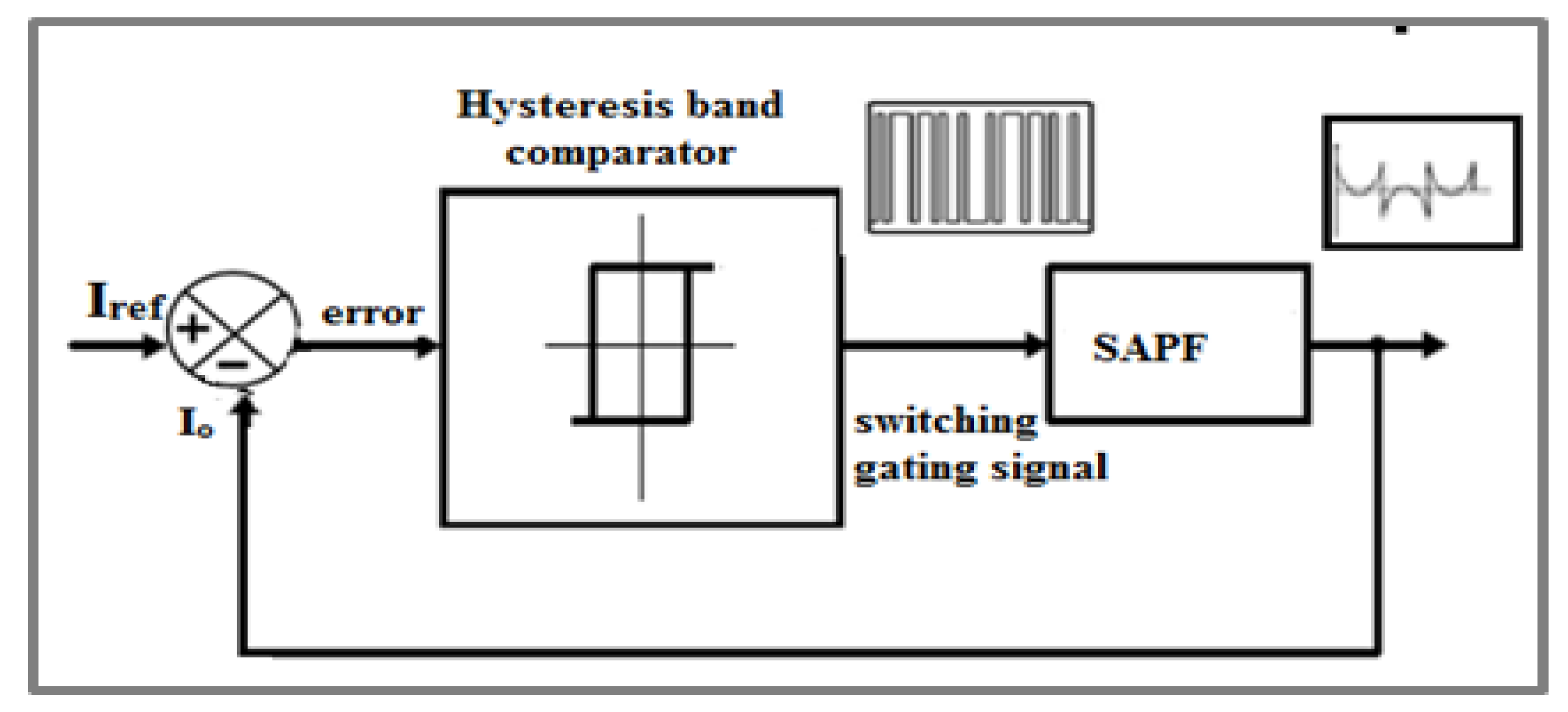
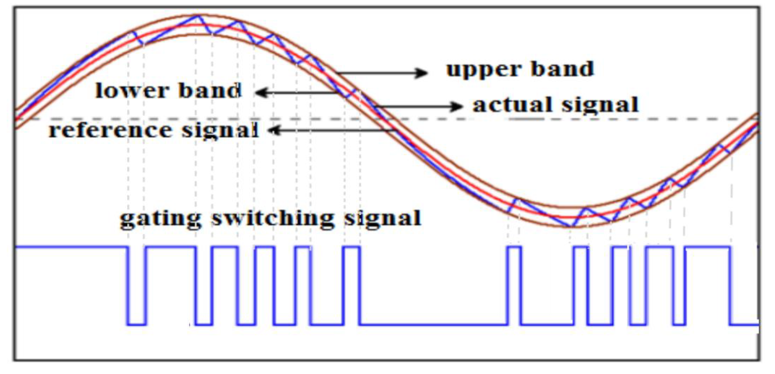
2.2.2. Hysteresis Band Current Controller

Hysteresis band current controllers are one of the most distinctive time-domain current controllers. In this controller, the SAPF is controlled so that the generated gating switching signals forced an actual filter current, I o ,   to follow the extracted reference harmonic current, I r e f . The principle of the proposed controller is comparing the harmonic reference current to the actual output current from the filter. Depending on the result, switching signals are generated, as shown in Figure 3. The hysteresis comparator takes lower and upper band limits around the reference harmonic current component. Therefore, if the actual SAPF current is less than the reference current, the commands are to increase the filter injected current. The commands are to decrease the filter injected current if the compared filter current is greater than the reference current. Figure 4 shows the waveforms of the hysteresis band current method. Equation (10) provides the current error signal that switches the IGBTs of the inverter.
I e r r o r = I r e f I o .
The operation of the four switches of the inverter (S1, S2, S3 and S4) with the hysteresis band current, Hb, is as follows:
S 2   and   S 4 O N   i f   ( I o < I r e f H b ) ,
S 1   and   S 3 O N   i f   (   I o > I r e f + H b ) .

2.2.3. Voltage Source Inverter

The inverter used as SAPF is a full-bridge voltage source inverter with two-leg four IGBTs switches. The inverter uses a DC-bus capacitor as the DC supply. It is switched at a high frequency to follow the extracted reference harmonic current with the generated threshold band. In addition, a filtering inductor is inserted between the inverter and the point of connection to the AC source to reduce the ripple in the injected compensating current exhibited from the switching of the inverter gates [35].
In linear loads, only the phase shift between fundamentals current and voltage defines the power factor of the source, Equation (13). On the contrary, the waveforms of current/voltage contain harmonic components in the state of nonlinear loads. When the waveform comprises harmonic components besides the fundamental, the power factor is determined as a function of phase shift, φ , and the %THD. Equation (18) explains the relationship between the power factor of nonlinear loads and the overall harmonic distortion.
P F = c o s φ
P F = V r m s   I 1 r m s c o s φ V r m s   I r m s =   I 1 r m s c o s φ   I r m s = K d c o s φ = K d K θ    
where
K d =   I 1 r m s   I r m s ,
% T H D = 100 1 K d 2 1 ,
K d = 1 1 + ( % T H D 100 ) 2 ,
P F = K θ K d = c o s φ 1 1 + ( % T H D 100 ) 2 .
The main function of low power, single-phase SAPF is to compensate for harmonics distortion, including in source current/voltage. The harmonics elimination means low %THD in the source waveform that is within the different defined standards. Thus, as explained in Equation (18), the lower the %THD, the higher the power factor of the source. It is worthy of confirming that the SAPF improves not only the total harmonic distortion but also enhances the power factor of the system. The FFT is processed in an Arduino microcontroller to compute the %THD and power factor of the source.

3. Simulation and Hardware Implementation for Single-Phase SAPF

The simulation for the SAPF is implemented utilizing a MATLAB/Simulink environment to prove the effectiveness of the model in reducing the THD level and investigating the power factor improvement. In addition, to simulate and test the prototype, Proteus Virtual System Modelling (VSM) is used. Proteus VSM enables system simulation with actual animated components. The hardware implementation and the results obtained will be introduced and discussed.

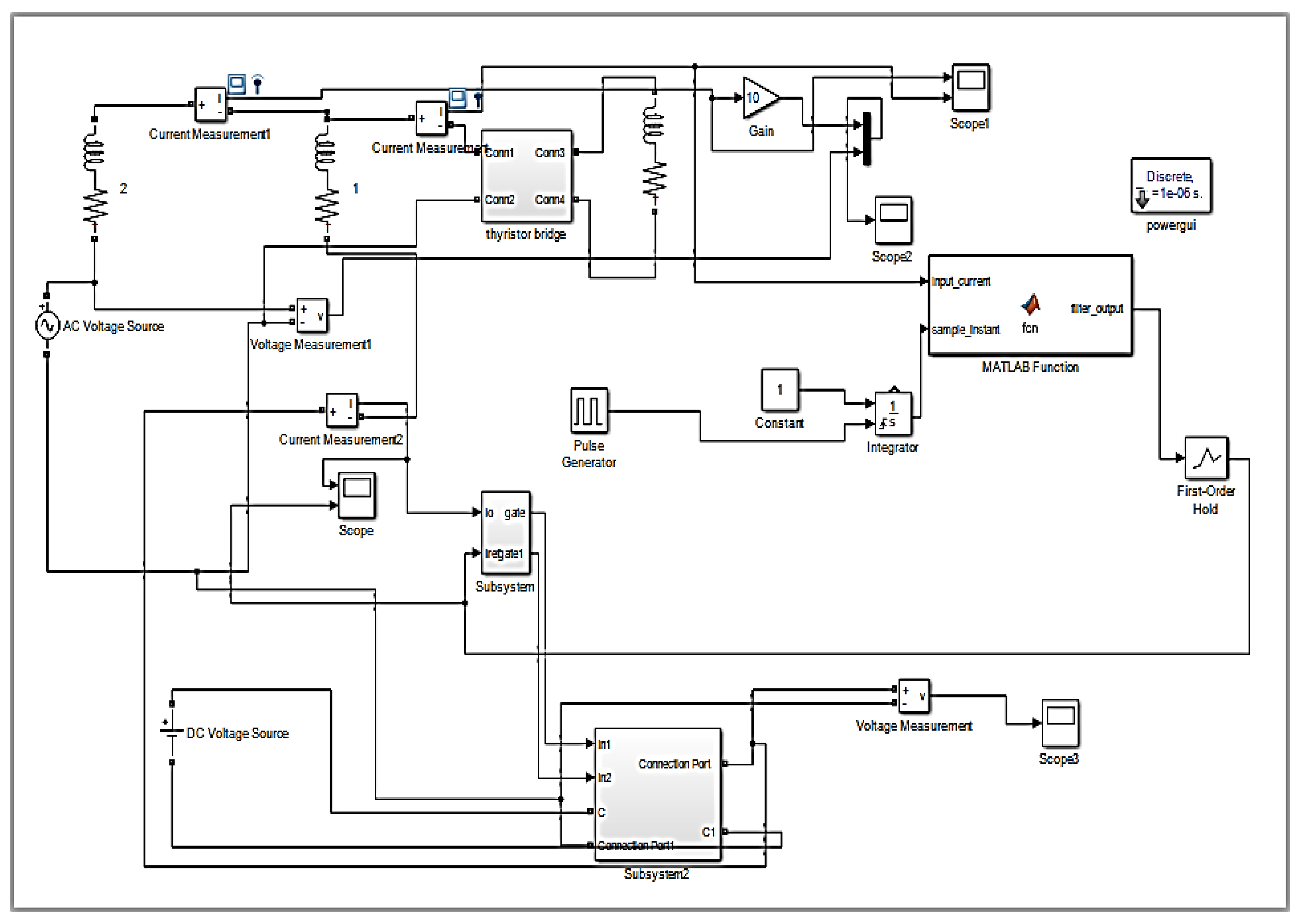
3.1. Simulation of SAPF Utilizing MATLAB/Simulink

Herein, the performance for a single-phase SAPF is tested using a MATLAB/Simulink environment. Table 1 describes the system parameters used in the simulation. The test system is a 220 V source supplying a nonlinear load. The SAPF is linked to parallel between the source and the load. The load is RL load supplied through the full-bridge converter, firing at 30°. The SAPF is connected through a filter interface resistance and an inductor. Figure 5 shows the simulation scheme of the test system for the reduction of THD. Measuring the power factor is performed using the FFT technique. The simulation of this model is shown in Figure 6.

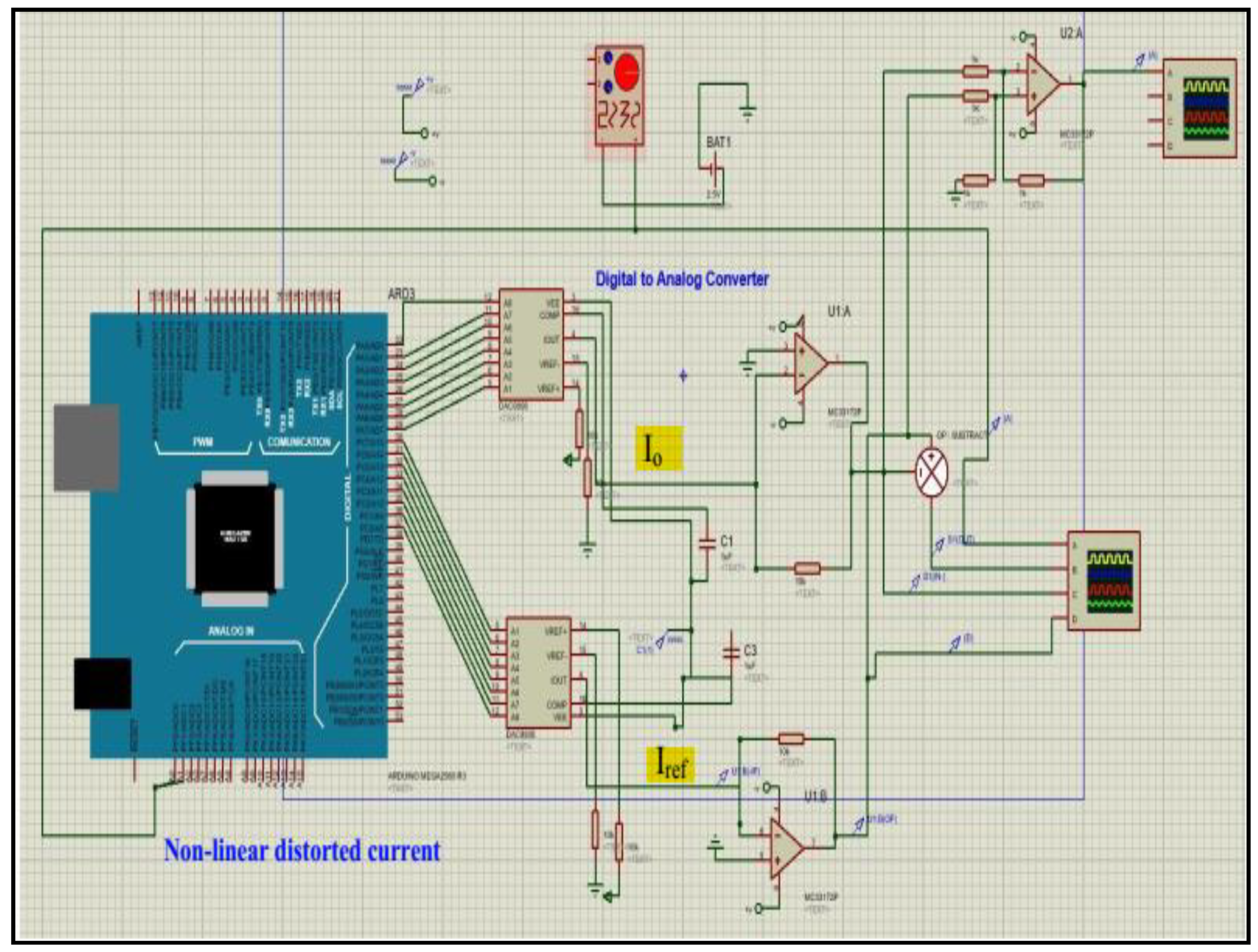
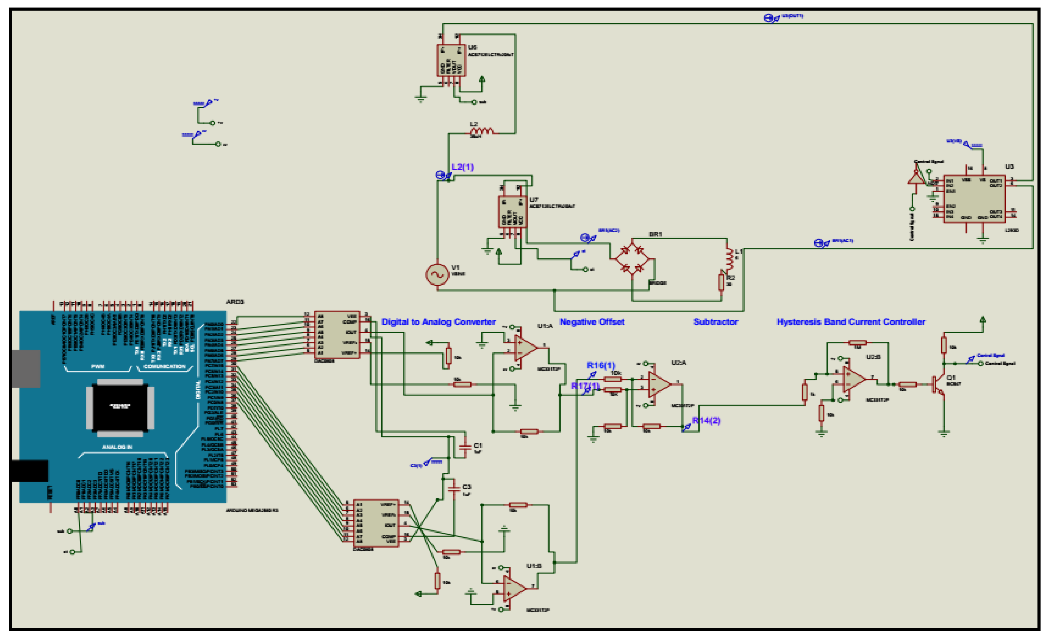
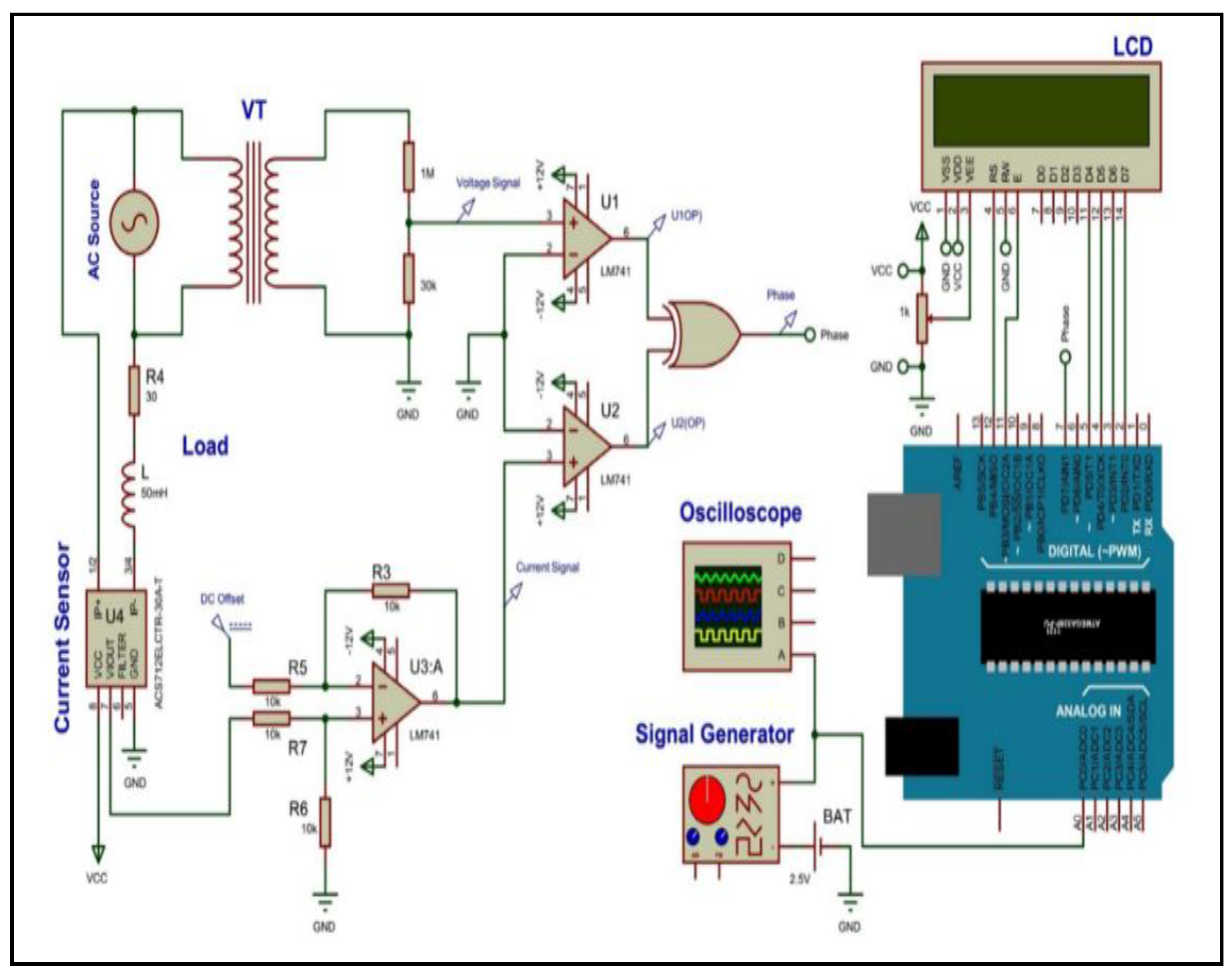
3.2. Simulation of SAPF Prototype Using Proteus Simulator

The implementation of a prototype system is tested using Proteus Virtual System Modelling (VSM) [38]. Proteus VSM enables system simulation with actual animated components. In addition, it facilitates the simulation of a microcontroller-based system. Proteus VSM enables developing and testing the design before actual hardware implementation. In this study, four stages, the nonlinear load, digital notch filter, hysteresis band current controller and the voltage source inverter, are implemented individually as the main SAPF design stages.

3.2.1. Nonlinear Load

The nonlinear load is represented by an RL load with an inductance L = 50 mH and a resistance R = 30 Ω, fed throughout the output from a full-wave bridge rectifier. The source voltage is 12 V AC from the autotransformer [13].

3.2.2. Digital Notch Filter

A notch filter is a discrete-time function represented by Equation (9). It has been programmed in the Arduino Mega microcontroller, as it has many features (e.g., more space, more input/output pins, high-speed communication and good protection). The load current was sensed by a Hall effect current transformer and fed to the ADC. The output of ADC is x(k) which is the digital input load current. The digital input load current is fed to the digital notch filter, whose output is y(k). y(k) represents the digital output signal from the filter with only extracted harmonic components. The output digital signal y(k) is then converted into analog signal y(t) with a DAC circuit. Figure 7 explains the simulation of the digital notch filter with an Arduino microcontroller.

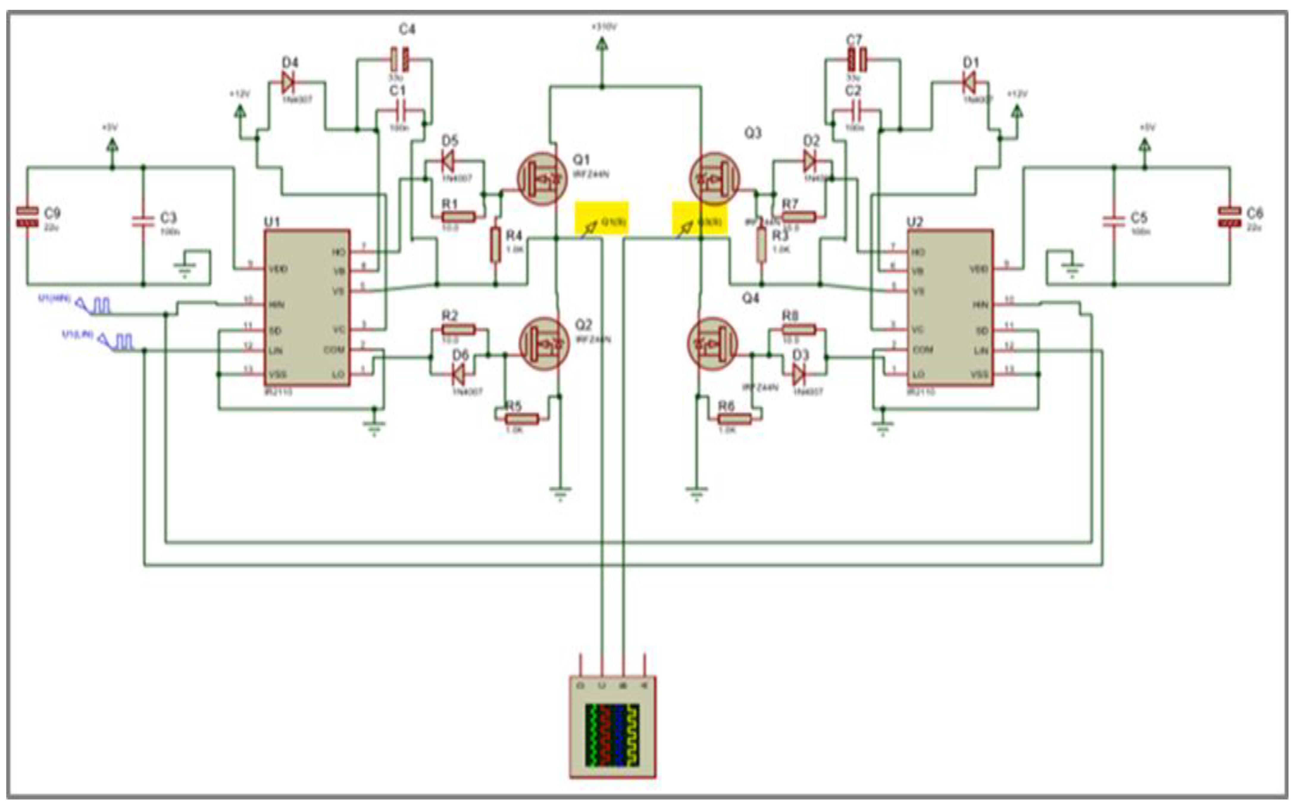
3.2.3. H-Bridge Voltage Source Inverter

Two pairs of MOSFET are utilized in the case of a single-phase H-bridge inverter. Each pair represents one side (high or low). It requires 12 or 15 V to be switched on or off. In order to facilitate applying the required voltage on both sides, a IR2110 IC driver is necessary. It requires a digital signal of 0/5 V as input, and it creates the required voltage across the gate of MOSFET. One IC driver is required to control each side of the bridge. Figure 8 shows the simulation scheme of the H-bridge circuit.

3.2.4. Hysteresis Band Current Controller (Schmitt Trigger) and Overall Simulation

A Schmitt trigger is used as a hysteresis band trigger. As shown in Figure 9, the Schmitt trigger represents an active circuit that converts the analog signal into digital output. It is a differential amplifier with positive feedback applied to the non-inverting input. It operates with a loop gain greater than 1. It maintains an unchanged output value until its input varies sufficiently within a defined band. In the non-inverting configurations, if the input exceeds a certain chosen band, the output is indicated as high, while the output is low if the input is lower than a certain chosen lower band. In between the upper and lower bands, the output remains unchanged. This dual-action represents the function of a hysteresis band conditioning circuit. The bands are generated by adding/subtracting a certain value to obtain the upper/lower band around the reference signal. In Figure 9, the overall simulation is performed with an illustration of different stages of SAPF. In addition, the simulation of the implemented power factor circuit using Proteus VMS is shown in Figure 10.

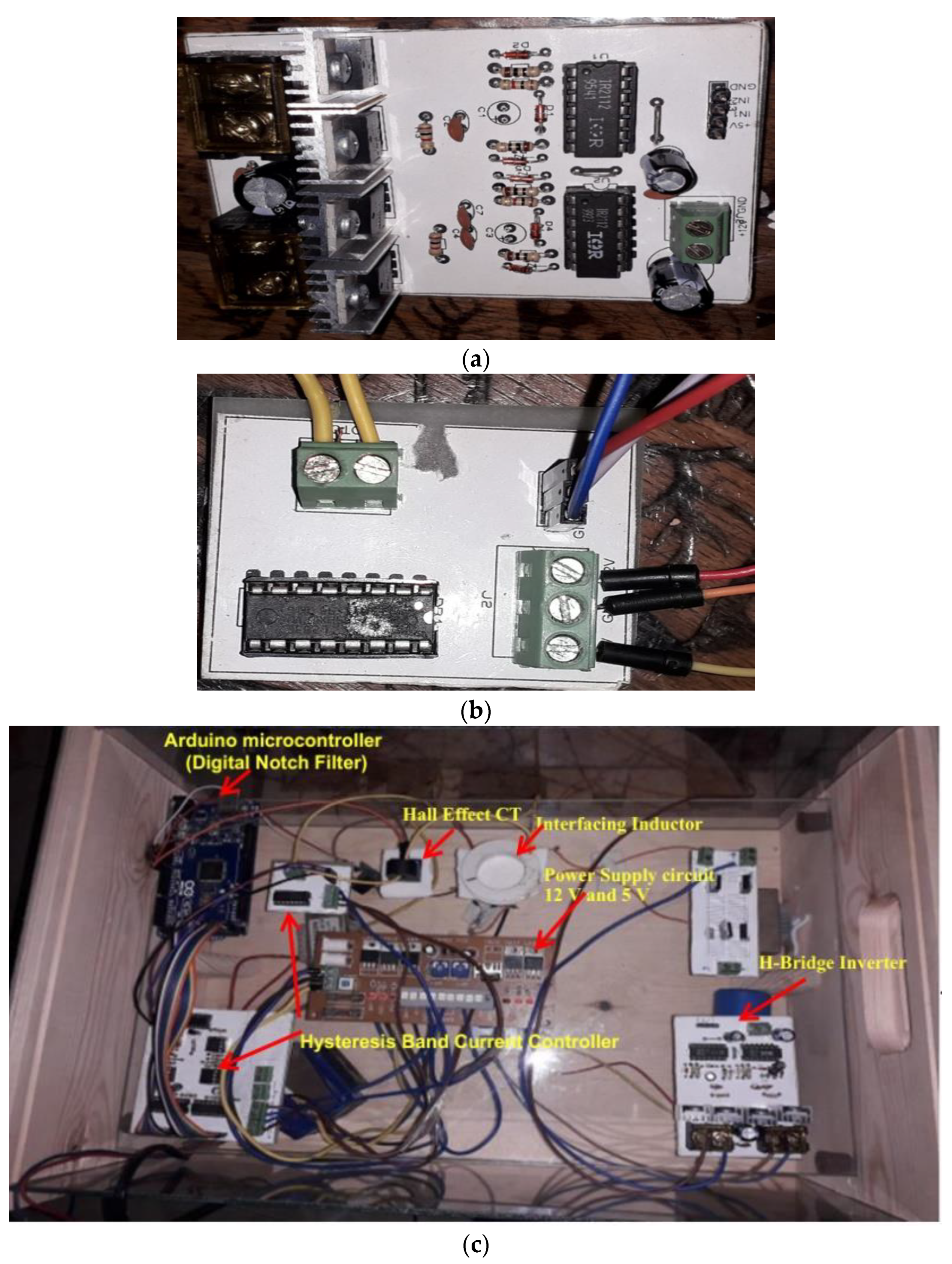
3.3. Hardware Implementation of SAPF

The complete prototype of a single-phase SAPF is implemented on hardware using an ac source of 12 V from an autotransformer, which supplies a nonlinear load through a full-bridge rectifier. The load consists of 30 Ω resistance and an inductor of 50 mH. The compensation for %THD and improving the power factor are implemented using the SAPF of two pairs of MOSFET IRF540 IC consisting of an H-bridge voltage source inverter (VSI). The VSI is connected to the AC side through an inductor of 75 mH and a resistance of 3.8 Ω. The VSI is connected to a DC-link capacitor of 12 DC voltage. An IR2110 IC driver drives the H-bridge. The MOSFETs gate signal is the Schmitt trigger output, which acts as the hysteresis band current controller. Figure 11 shows the hardware implementation of the single-phase SAPF using PCB layout.
In this design, the Arduino Mega microcontroller was used for the implementation of the digital notch filter. The Hall effect current or voltage signal senses the analogy signal and feeds it to the Mega Arduino microcontroller through ADC. Arduino microcontroller digital outputs are converted to analogue signals using DAC 0808 IC.
The harmonic component extracted by the digital notch filter is considered the harmonic reference component. This current and the actual output for the inverter are the input to the Schmitt trigger controller. The gate signal is the output of the trigger circuit that takes a band of 5% as a comparator band current. The closed-loop compensation of the harmonics of the source waveform enables actual and continuous reduction of the %THD and the power factor enhancement.

4. Results and Discussion

Herein, the results of system simulation using both a MATLAB/Simulink environment and Proteus VMS are discussed in the following subsections.

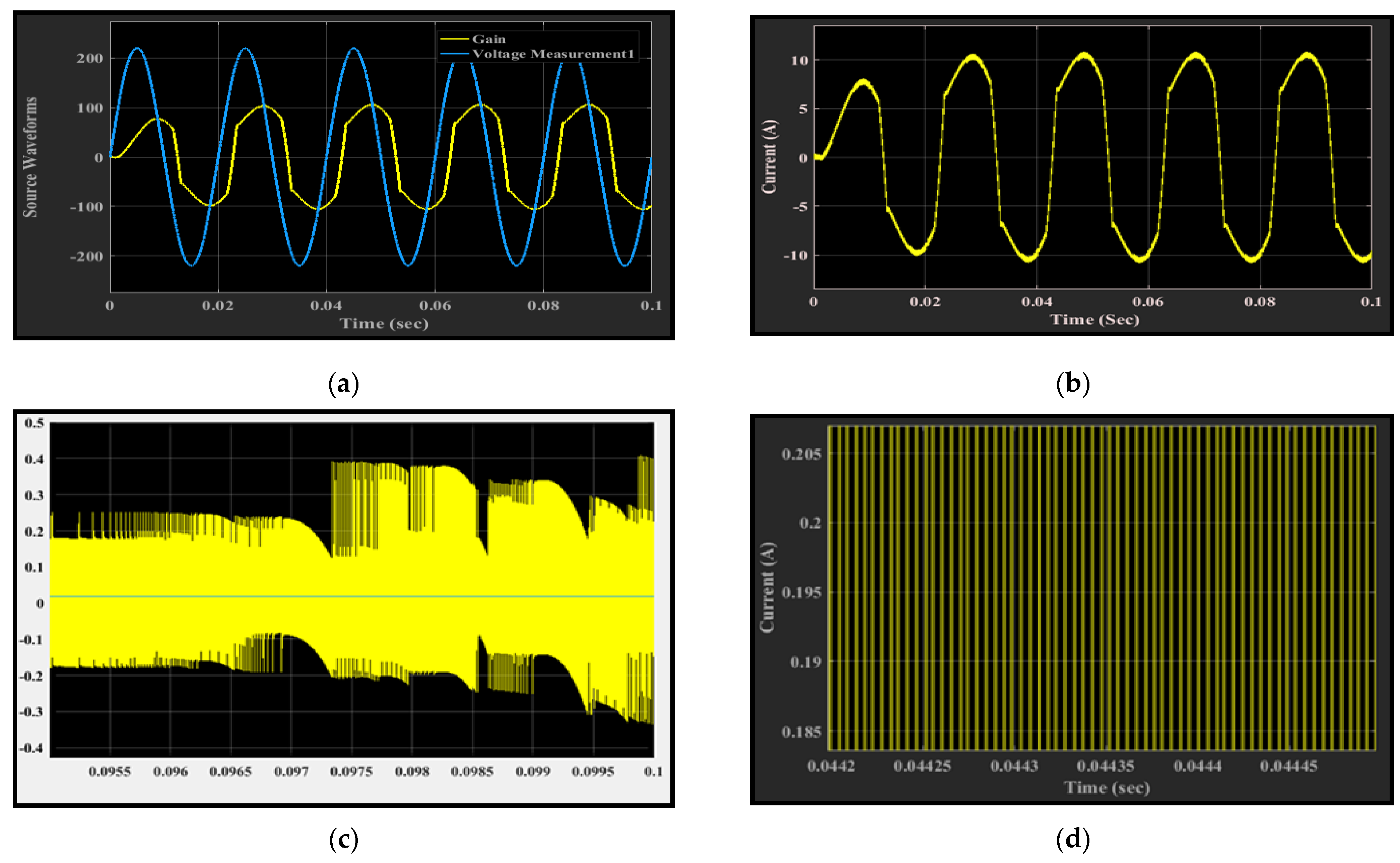
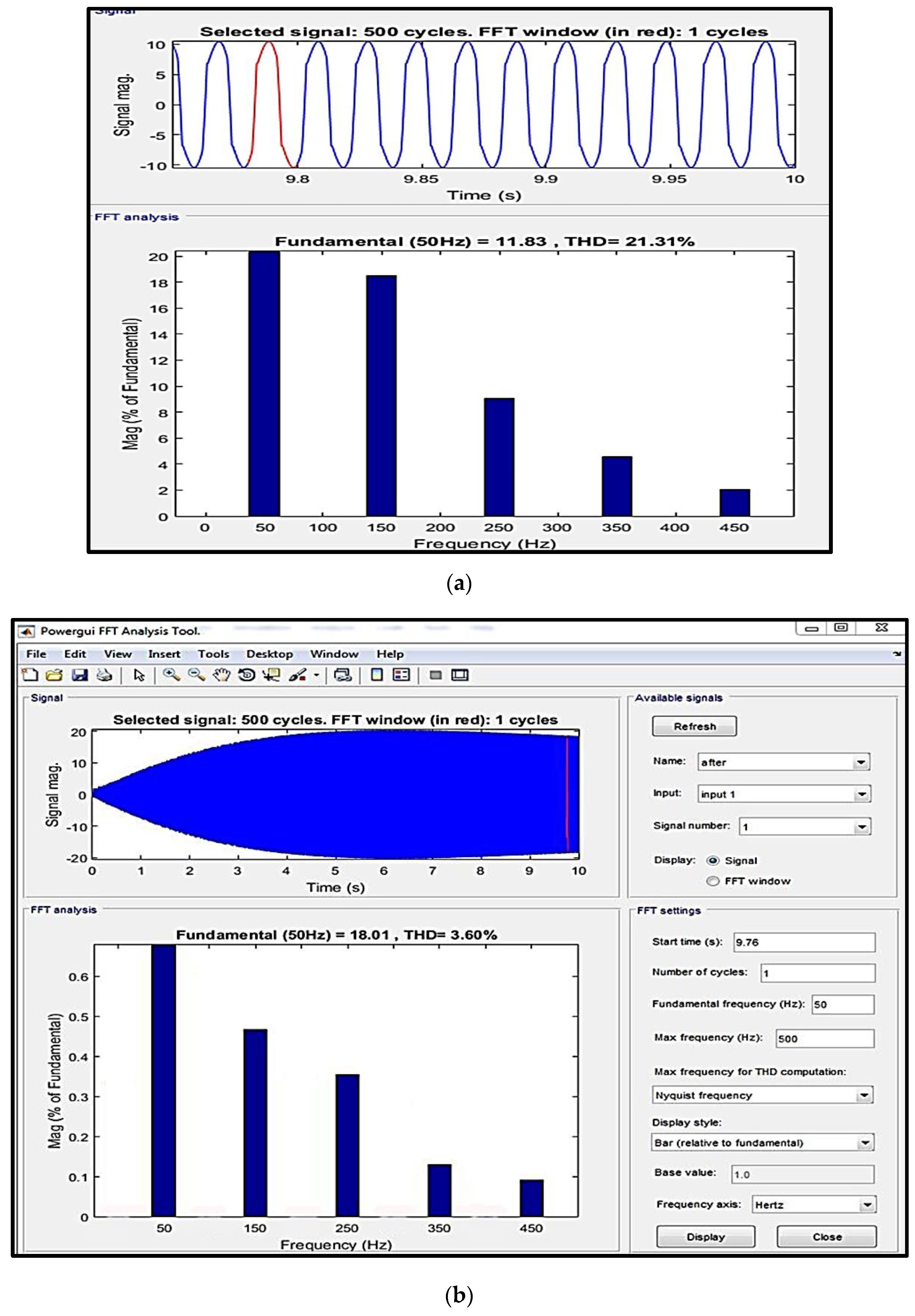
4.1. Simulation Results of SAPF Using MATLAB/Simulink

The THD due to the simulated nonlinear load before compensation is reported as 21.31%, which exceeds the 5% value set by IEEE standards. After compensating for the current harmonics using SAPF with a digital notch filter, the value of THD is reduced to 3.6%that is within the bounds of the acceptable levels determined by IEEE standards. The current waveform of the nonlinear load, source current together with voltage before compensating the output of the filter and the output signal of the hysteresis band current controller are depicted in Figure 12. Simulation results for the FFT technique for %THD before and after compensation are shown in Figure 13. The FFT analysis confirms the ability of SAPF to reduce the %THD, as it is reduced from 21.31% to 3.6%. As the %THD has a major effect on the power factor for the source waveform, the simulation of power factor measurement illustrates an improvement in power factor after current harmonics compensation. The reported results illustrate an enhancement in the power factor from 0.8098 before compensation to 0.9337 after using SAPF.

4.2. Simulation Results of SAPF Using Proteus Simulator

The simulation results of the prototype of SAPF show the waveforms for the source voltage and current due to nonlinear load. It is shown in Figure 14 that the current waveform is distorted and contains harmonics, which explains the must to compensate for these harmonics. The digital notch filter controller of SAPF compensates for these distortions. Figure 15 explains the simulation results of notch filter signals used to detect and compensate for current harmonics. In addition, the harmonic reference current generated from the digital notch filter, I r e f , used in the hysteresis band current controller and the actual current out from the SAPF, I o , are illustrated in Figure 16. The current signal results in the required injected harmonic are compared to the coupling point of the power source in order to reduce the THD and compensate for the power factor. The simulated results of the compensated current waveform are shown in Figure 17. The current waveform has lower distortion and good shape.

5. Conclusions

In this study, SAPF was introduced as an effective method to enhance power factor and reduce %THD to a level within that of IEEE Std. 519-1992 and IEEE Std. 519-2014. The improvement of harmonic distortion and power factor optimizes the power quality issue. To implement the desired SAPF, a simulation of single-phase SAPF was achieved using a MATLAB/Simulink environment. In this regard, the results confirm the ability and the effectiveness of SAPF in improving the power system quality and decreasing %THD from 21.31% to 3.6%, which is lower than the defined level of different standards. In addition, a significant improvement in the power factor was reported, as it increased from 0.8098 to 0.9337. To build up the actual system, a prototype design was built and tested at a voltage source of 12 V. The pre-test of the proposed design was achieved using Proteus VMS. The prototype was implemented using a PCB layout. The results emphasize the importance of SAPF to eliminate harmonics and enhance power factor. In addition, the response was instantaneous and adaptive in nature. It can be concluded that SAPF has two very important features, as it eliminates the most distortion of source waveform, and at the same time, it compensates for the source power factor at different loading conditions.
In the future, the design of an active power filter using different optimization algorithms should be considered in addition to a multi-objective formulation of the target problem to minimize the individual harmonic indices and the total harmonic distortions. Examples of the proposed methods used to solve the harmonic mitigation based on optimization methods are the equilibrium optimization algorithm [39], crow search optimizer [40], sine cosine algorithm [41], etc. In addition, studying single-phase and three-phase series active filters with different controllers must be considered.

Author Contributions

Conceptualization, A.A., R.A.E.-S., M.S., R.M.G. and A.F.B.; Data curation, A.A., R.A.E.-S., M.S., R.M.G. and A.F.B.; Formal analysis, A.A., R.A.E.-S., M.S., R.M.G. and A.F.B. Funding acquisition, R.M.G.; Investigation, A.A., R.A.E.-S., M.S. and A.F.B.; Methodology, A.A., R.A.E.-S., M.S., R.M.G. and A.F.B.; Resources, A.A., R.A.E.-S. and A.F.B.; Software, A.A., R.A.E.-S., M.S., R.M.G. and A.F.B.; Supervision, A.A., R.A.E.-S., M.S., R.M.G. and A.F.B.; Visualization, A.A., R.A.E.-S., M.S., R.M.G. and A.F.B.; Writing—original draft, A.A., R.A.E.-S., M.S., R.M.G. and A.F.B.; Writing—review & editing, A.A., R.A.E.-S., M.S., R.M.G. and A.F.B. All authors have read and agreed to the published version of the manuscript.

Funding

Princess Nourah bint Abdulrahman University Researchers Supporting Project number (PNURSP2022R138), Princess Nourah bint Abdulrahman University, Riyadh, Saudi Arabia.

Acknowledgments

The authors acknowledge Princess Nourah bint Abdulrahman University Researchers Supporting Project number (PNURSP2022R138), Princess Nourah bint Abdulrahman University, Riyadh, Saudi Arabia.

Conflicts of Interest

The authors declare no conflict of interest and no financial competing interest.

References

  1. Martins, A.P. The use of an active power filter for harmonic elimination and power quality improvement in a nonlinear loaded electrical installation. In Proceedings of the International Conference on Renewable Energies and Power Quality, ICREPQ, Vigo, Spain, 9–12 April 2003; Volume 3. [Google Scholar]
  2. Boukezata, B.; Chaoui, A.; Gaubert, J.-P.; Hachemi, M. Power Quality Improvement by an Active Power Filter in Grid-connected Photovoltaic Systems with Optimized Direct Power Control Strategy. Electr. Power Compon. Syst. 2016, 44, 2036–2047. [Google Scholar] [CrossRef]
  3. Rameshkumar, K.; Indragandhi, V.; Palanisamy, K.; Arunkumari, T. Model Predictive Current Control of Single Phase Shunt Active Power Filter. Energy Procedia 2017, 117, 658–665. [Google Scholar] [CrossRef]
  4. Das, S.; Ray, P.; Sahoo, A.; Ramasubbareddy, S.; Babu, T.; Kumar, N.; Elavarasan, R.; Mihet-Popa, L. A Comprehensive Survey on Different Control Strategies and Applications of Active Power Filters for Power Quality Improvement. Energies 2021, 14, 4589. [Google Scholar] [CrossRef]
  5. Rani, R.S.; Rao, C.S.; Kumar, M.V. PSPWM based Five-Level Shunt Active Filter for Power Quality Improvement in Power System Network. Energy Procedia 2017, 117, 794–801. [Google Scholar] [CrossRef]
  6. Agrawal, S.; Vaishnav, S.K.; Somani, R.K. Active Power Filter for Harmonic Mitigation of Power Quality Issues in Grid Integrated Photovoltaic Generation System. In Proceedings of the 2020 7th International Conference on Signal Processing and Integrated Networks (SPIN), Noida, India, 27–28 February 2020; IEEE: Piscataway, NJ, USA, 2020. [Google Scholar]
  7. Martins, A.; Ferreira, J.; Azevedo, H. Active power filters for harmonic elimination and power quality improvement. In Power Quality; InTech: London, UK, 2011. [Google Scholar]
  8. De Araujo Ribeiro, R.L.; de Azevedo, C.C.; de Sousa, R.M. A robust adaptive control strategy of active power filters for power-factor correction, harmonic compensation, and balancing of nonlinear loads. IEEE Trans. Power Electron. 2011, 27, 718–730. [Google Scholar] [CrossRef]
  9. Jain, S.; Agrawal, P.; Gupta, H. Fuzzy logic controlled shunt active power filter for power quality improvement. IEE Proc.-Electr. Power Appl. 2002, 149, 317–328. [Google Scholar] [CrossRef]
  10. Tang, Y.; Loh, P.C.; Wang, P.; Choo, F.H.; Gao, F.; Blaabjerg, F. Generalized Design of High Performance Shunt Active Power Filter With Output LCL Filter. IEEE Trans. Ind. Electron. 2011, 59, 1443–1452. [Google Scholar] [CrossRef]
  11. Asirninoaei, L.; Blaabjerg, F.; Hansen, S. Evaluation of harmonic detection methods for active power filter applications. In Proceedings of the Twentieth Annual IEEE Applied Power Electronics Conference and Exposition, 2005, APEC 2005, Austin, TX, USA, 6–10 March 2005; IEEE: Piscataway, NJ, USA, 2005; Volume 1. [Google Scholar]
  12. Izhar, M.; Hadzer, C.; Syafrudin, M.; Taib, S.; Idris, S. Performance for passive and active power filter in reducing harmonics in the distribution system. In Proceedings of the PECon 2004. Proceedings. National Power and Energy Conference, 2004, Kuala Lumpur, Malaysia, 29–30 November 2004; IEEE: Piscataway, NJ, USA, 2004. [Google Scholar]
  13. Ullah, A.; Sheikh, I.U.H.; Arshad, S.; Saleem, F. Digital active power filter controller design for current harmonics in power system. In Proceedings of the 2019 16th International Bhurban Conference on Applied Sciences and Technology (IBCAST), Islamabad, Pakistan, 8–12 January 2019; IEEE: Piscataway, NJ, USA, 2019. [Google Scholar]
  14. Shyu, K.-K.; Yang, M.-J.; Chen, Y.-M.; Lin, Y.-F. Model Reference Adaptive Control Design for a Shunt Active-Power-Filter System. IEEE Trans. Ind. Electron. 2008, 55, 97–106. [Google Scholar] [CrossRef]
  15. Akagi, H.; Watanabe, E.H.; Aredes, M. Instantaneous Power Theory and Applications to Power Conditioning; IEEE Press: Piscataway, NJ, USA, 2007. [Google Scholar]
  16. Magdum, P.S.; Patil, U.T. Development of single-phase shunt active power filter. In Proceedings of the 2017 International Conference on Inventive Communication and Computational Technologies (ICICCT), Coimbatore, India, 27–28 February 2020; IEEE: Piscataway, NJ, USA, 2017. [Google Scholar]
  17. Khadkikar, V.; Chandra, A.; Singh, B.N. Generalized single-phase p-q theory for active power filtering: Simulation and DSP-based experimental investigation. IET Power Electron. 2009, 2, 67–78. [Google Scholar] [CrossRef] [Green Version]
  18. Mattavelli, P. A closed-loop selective harmonic compensation for active filters. IEEE Trans. Ind. Appl. 2001, 37, 81–89. [Google Scholar] [CrossRef] [Green Version]
  19. Chilipi, R.S.R.; Sayari, N.A.; Hosani, K.H.A.; Beig, A.R. Adaptive Notch Filter-Based Multipurpose Control Scheme for Grid- Interfaced Three-Phase Four-Wire DG Inverter. IEEE Trans. Ind. Appl. 2017, 53, 4015–4027. [Google Scholar] [CrossRef]
  20. Kusljevic, M. Simultaneous Frequency and Harmonic Magnitude Estimation Using Decoupled Modules and Multirate Sampling. IEEE Trans. Instrum. Meas. 2009, 59, 954–962. [Google Scholar] [CrossRef]
  21. Kumar, P.; Mahajan, A. Soft Computing Techniques for the Control of an Active Power Filter. IEEE Trans. Power Deliv. 2008, 24, 452–461. [Google Scholar] [CrossRef]
  22. Abbas, A.S.; El-Sehiemy, R.A.; Abou El-Ela, A.; Ali, E.S.; Mahmoud, K.; Lehtonen, M.; Darwish, M.M. Optimal harmonic mitigation in distribution systems with inverter based distributed generation. Appl. Sci. 2021, 11, 774. [Google Scholar] [CrossRef]
  23. Hou, S.; Fei, J.; Chen, C.; Chu, Y. Finite-Time Adaptive Fuzzy-Neural-Network Control of Active Power Filter. IEEE Trans. Power Electron. 2019, 34, 10298–10313. [Google Scholar] [CrossRef]
  24. George, M.; Basu, K.P. Modeling and Control of Three-Phase Shunt Active Power Filter 1. 2008. Available online: https://thescipub.com/pdf/ajassp.2008.1064.1070.pdf (accessed on 1 January 2022).
  25. Cirrincione, M.; Pucci, M.; Vitale, G.; Miraoui, A. Current Harmonic Compensation by a Single-Phase Shunt Active Power Filter Controlled by Adaptive Neural Filtering. IEEE Trans. Ind. Electron. 2009, 56, 3128–3143. [Google Scholar] [CrossRef]
  26. Kale, M.; Ozdemir, E. A novel adaptive hysteresis band current controller for shunt active power filter. In Proceedings of the 2003 IEEE Conference on Control Applications, 2003, CCA 2003, Istanbul, Turkey, 25 June 2003; IEEE: Piscataway, NJ, USA, 2003; Volume 2. [Google Scholar]
  27. Vazquez, J.; Salmeron, P. Active power filter control using neural network technologies. IEE Proc.-Electr. Power Appl. 2003, 150, 139–145. [Google Scholar] [CrossRef]
  28. Milasi, R.M.; Lynch, A.F.; Li, Y. Adaptive control of an active power filter for harmonic suppression and power factor correction. Int. J. Dyn. Control 2021, 10, 473–482. [Google Scholar] [CrossRef]
  29. Khan, A.; Jaffery, M.H.; Javed, Y.; Arshad, J.; Rehman, A.U.; Khan, R.; Bajaj, M.; Kaabar, M.K.A. Hardware-in-the-Loop Implementation and Performance Evaluation of Three-Phase Hybrid Shunt Active Power Filter for Power Quality Improvement. Math. Probl. Eng. 2021, 2021, 8032793. [Google Scholar] [CrossRef]
  30. De Souza, L.L.; Rocha, N.; Fernandes, D.A.; De Sousa, R.P.; Jacobina, C.B. Grid Harmonic Current Correction Based on Parallel Three-Phase Shunt Active Power Filter. IEEE Trans. Power Electron. 2021, 37, 1422–1434. [Google Scholar]
  31. Echalih, S.; Abouloifa, A.; Lachkar, I.; Guerrero, J.M.; Hekss, Z.; Giri, F. Hybrid automaton-fuzzy control of single phase dual buck half bridge shunt active power filter for shoot through elimination and power quality improvement. Int. J. Electr. Power Energy Syst. 2021, 131, 106986. [Google Scholar] [CrossRef]
  32. Thananukul, P.; Kamsuwan, Y. Active Power Filter in Linear Systems for Power Factor Correction. In Proceedings of the 2021 3rd International Conference on Smart Power & Internet Energy Systems (SPIES), Shanghai, China, 25–28 September 2021; IEEE: Piscataway, NJ, USA, 2021. [Google Scholar]
  33. Singh, V.; Gupta, S.; Yadav, A.; Rajashekar, J. Harmonic Reduction and Reactive Power Improvement using Shunt Active Power Filter And Thyristor-Controlled Reactor. In Proceedings of the 2022 Second International Conference on Power, Control and Computing Technologies (ICPC2T), Raipur, India, 1–3 March 2022; IEEE: Piscataway, NJ, USA, 2022. [Google Scholar]
  34. Espinosa, T.B.P.; Magwili, G.V. Synchronous Reference Frame Method with PLL and Hysteresis Current Controller for Three Phase Shunt Active Power Filter to Mitigate Harmonics Caused by Nonlinear Loads. In Proceedings of the 2022 14th International Conference on Computer and Automation Engineering (ICCAE), Brisbane, Australia, 25–27 March 2022; IEEE: Piscataway, NJ, USA, 2022. [Google Scholar]
  35. Pinto, J.G.; Neves, P.; Pregitzer, R.G.; Monteiro, L.F.; Afonso, J.L. Single-phase shunt active filter with digital control. In Proceedings of the ICREPQ’07—International Conference on Renewable Energies and Power Quality, Seville, Spain, 28–30 March 2007; ISBN 978-84-611-4707-6. [Google Scholar]
  36. Srinath, S.; Prabakaran, S.; Mohan, K.; Selvan, M.P. Implementation of Single Phase Shunt Active Filter for Low Voltage Distribution System. In Proceedings of the 16th National Power Systems Conference, Hyderabad, India, 15–17 December 2010. [Google Scholar]
  37. Babu, N.; Guerrero, J.M.; Siano, P.; Peesapati, R.; Panda, G. An improved adaptive control strategy in grid-tied PV system with active power filter for power quality enhancement. IEEE Syst. J. 2021, 15, 2859–2870. [Google Scholar] [CrossRef]
  38. The PCB Library. Available online: https://www.componentsearchengine.com/pcb_library/proteus (accessed on 1 January 2022).
  39. Abdul-Hamied, D.T.; Shaheen, A.M.; Salem, W.A.; Gabr, W.I.; El-Sehiemy, R.A. Equilibrium optimizer based multi dimensions operation of hybrid AC/DC grids. Alex. Eng. J. 2020, 59, 4787–4803. [Google Scholar] [CrossRef]
  40. Shaheen, A.M.; El-Sehiemy, R.A. Optimal allocation of capacitor devices on MV distribution networks using crow search algorithm. CIRED-Open Access Proc. J. 2017, 2017, 2453–2457. [Google Scholar] [CrossRef] [Green Version]
  41. Rizk-Allah, R.M.; Mageed, H.M.A.; El-Sehiemy, R.; Aleem, S.A.; El Shahat, A. A New Sine Cosine Optimization Algorithm for Solving Combined Non-Convex Economic and Emission Power Dispatch Problems. Int. J. Energy Convers. 2017, 5, 180–192. [Google Scholar] [CrossRef]
Figure 1. Shunt active power filter structure.
Electronics 11 02205 g001
Figure 2. Notch filter of passive element (a) equivalent circuit; (b) frequency response.
Electronics 11 02205 g002
Figure 3. Hysteresis current controller response.
Electronics 11 02205 g003
Figure 4. Hysteresis band current waveforms.
Electronics 11 02205 g004
Figure 5. Simulation of single-phase SAPF by MATLAB/ Simulink environment.
Electronics 11 02205 g005
Figure 6. Simulated power factor circuit in MATLAB/ Simulink environment.
Electronics 11 02205 g006
Figure 7. Simulation scheme of digital notch filter signals using Proteus VMS.
Electronics 11 02205 g007
Figure 8. Implementation of H-bridge voltage source inverter using Proteus VMS.
Electronics 11 02205 g008
Figure 9. Overall design of SAPF using Proteus VMS.
Electronics 11 02205 g009
Figure 10. Implemented circuit for power factor measurement using Proteus VMS.
Electronics 11 02205 g010
Figure 11. Hardware implementation of single-phase SAPF using DSP board (a) H-Bridge Inverter for 220 V load; (b) H-Bridge Inverter for 12 V load; (c) overall design of single-phase SAPF.
Electronics 11 02205 g011
Figure 12. Simulation results of single-phase SAPF by MATLAB/ Simulink environment (a) source voltage waveform; (b) load current; (c) actual output current from SAPF (Io); (d) gate signal (output of hysteresis controller).
Electronics 11 02205 g012
Figure 13. Harmonic analysis of single-phase SAPF by FFT in MATLAB/Simulink environment (a) before compensation; (b) after compensation.
Electronics 11 02205 g013
Figure 14. Current and voltage waveform of the nonlinear.
Electronics 11 02205 g014
Figure 15. Simulation results of digital notch filter signals using Proteus VMS. (a) Nonlinear current waveform; (b) harmonic current waveform.
Electronics 11 02205 g015
Figure 16. Simulation results of SAPF based on Proteus VMS, (R16 (1): Io; R14 (2): Iref; L2 (1): source voltage).
Electronics 11 02205 g016
Figure 17. Current waveform after compensating by SAPF.
Electronics 11 02205 g017
Table 1. System parameters for MATLAB/Simulink.
ParameterValue
AC source: voltage220
AC source: impedanceResistance: 0.002 Ω, inductor of 20 mH
AC source: frequency50 Hz
Nonlinear load impedanceResistance: 10 Ω, inductor of 100 mH
Filter interface impedanceResistance: 0.5 Ω, inductor of 1 mH
Firing angle of the converter30°
DC-bus capacitor: voltage330 V
Publisher’s Note: MDPI stays neutral with regard to jurisdictional claims in published maps and institutional affiliations.

