
Development of Metamaterial Inspired Non-Uniform Circular Array Superstate Antenna Using Characteristic Mode Analysis

 ,
,  ,
,  ,
,  ,
,
Abstract
:1. Introduction
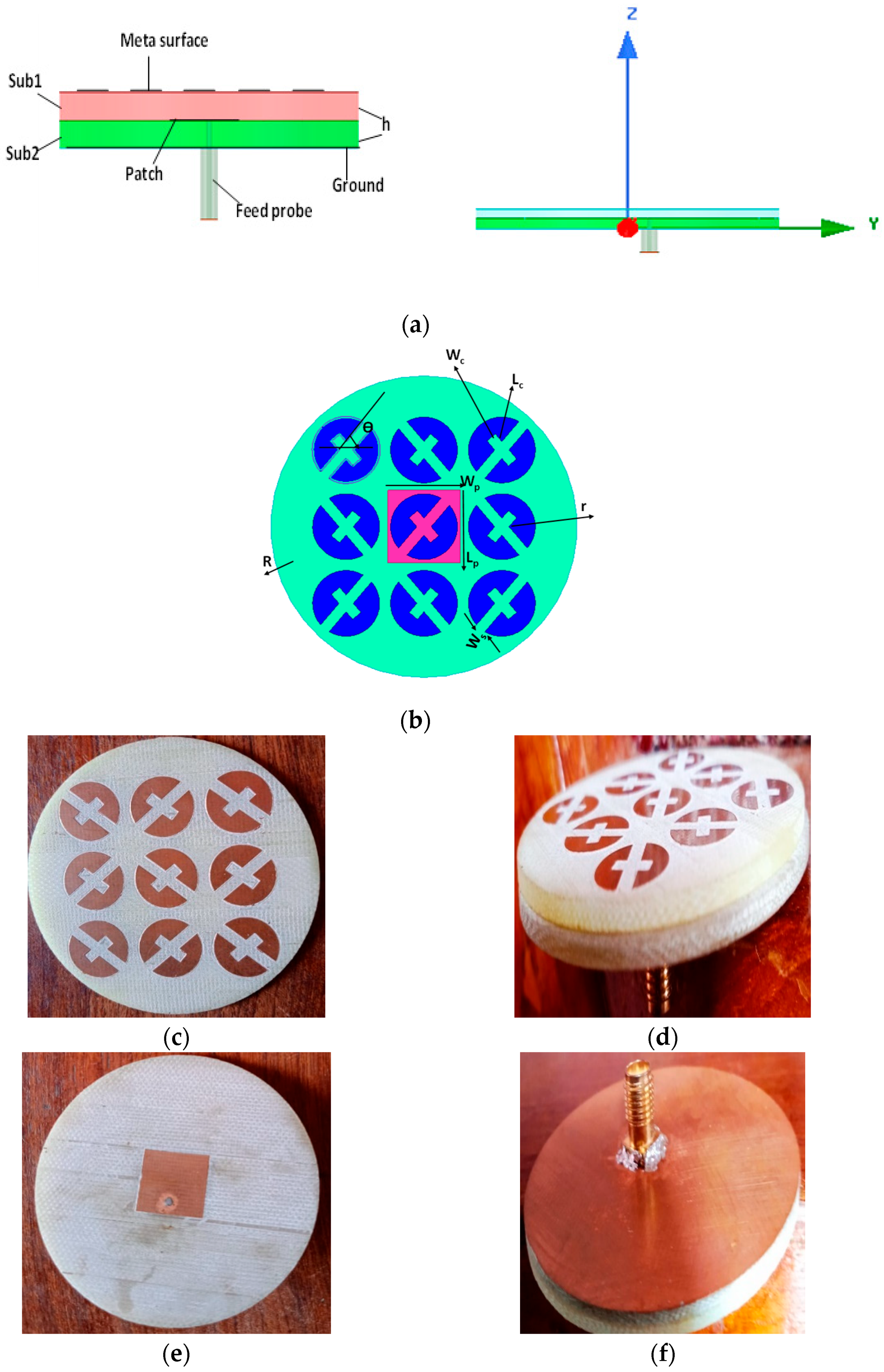
2. Antenna Design
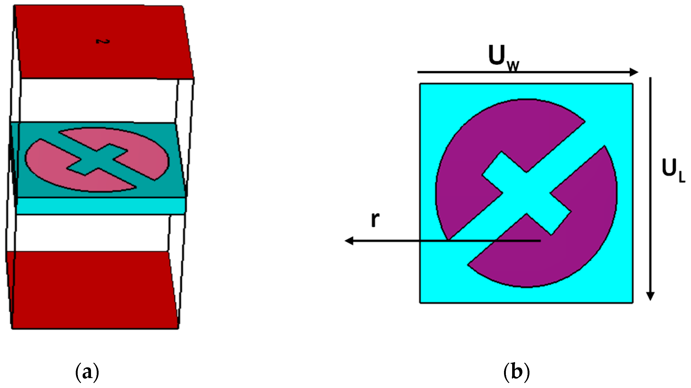
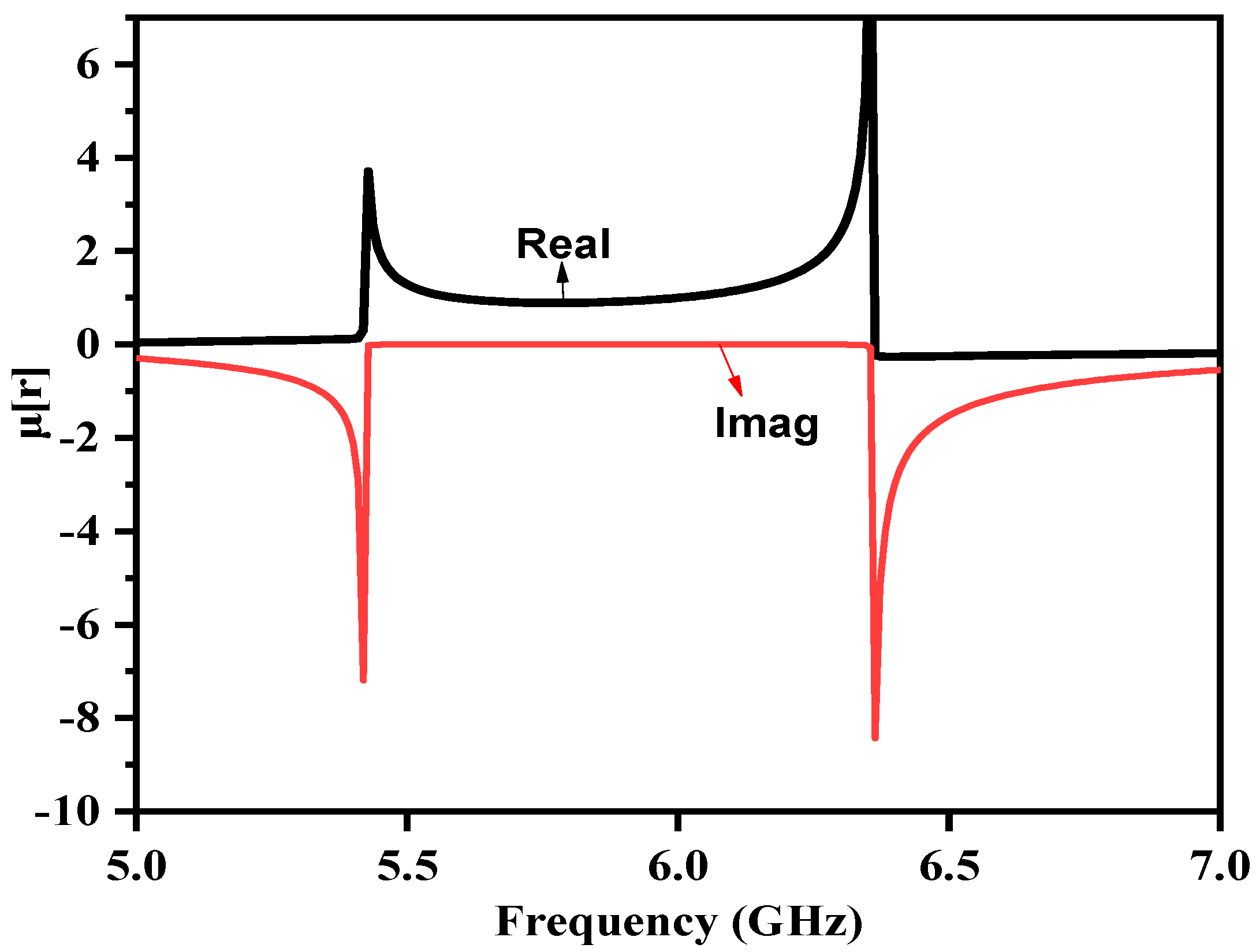
3. Unit Cell Design
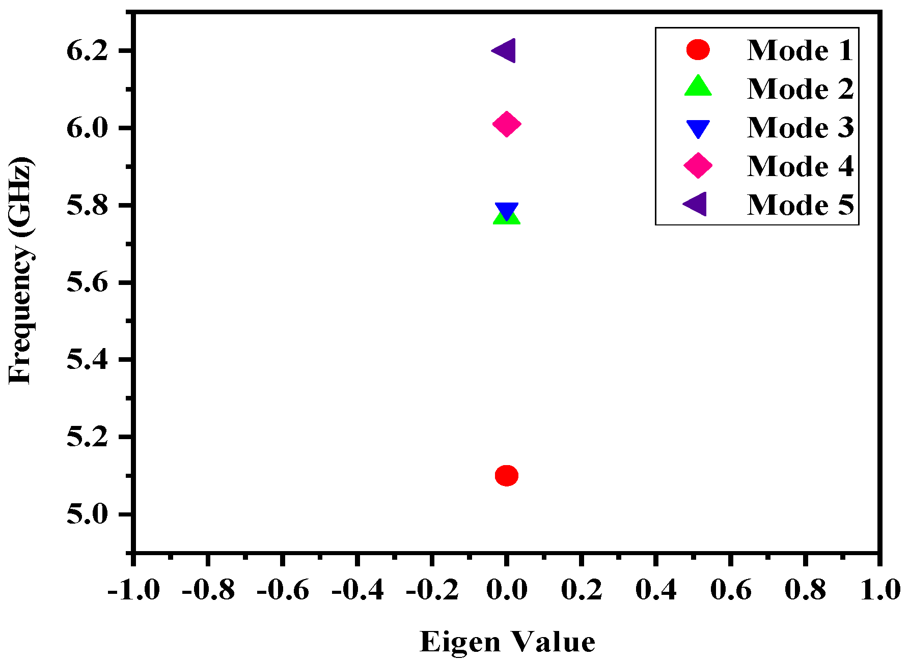
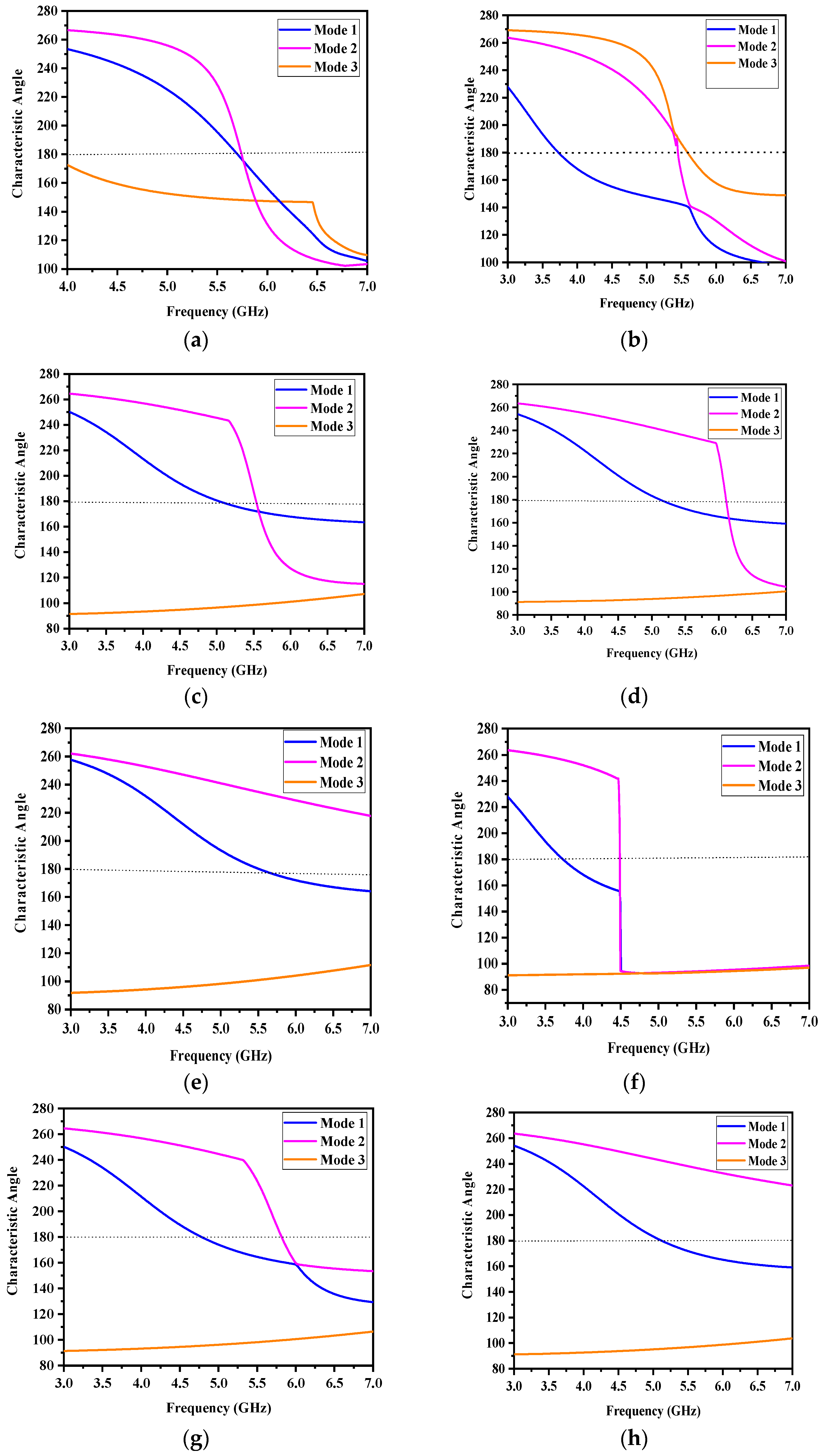
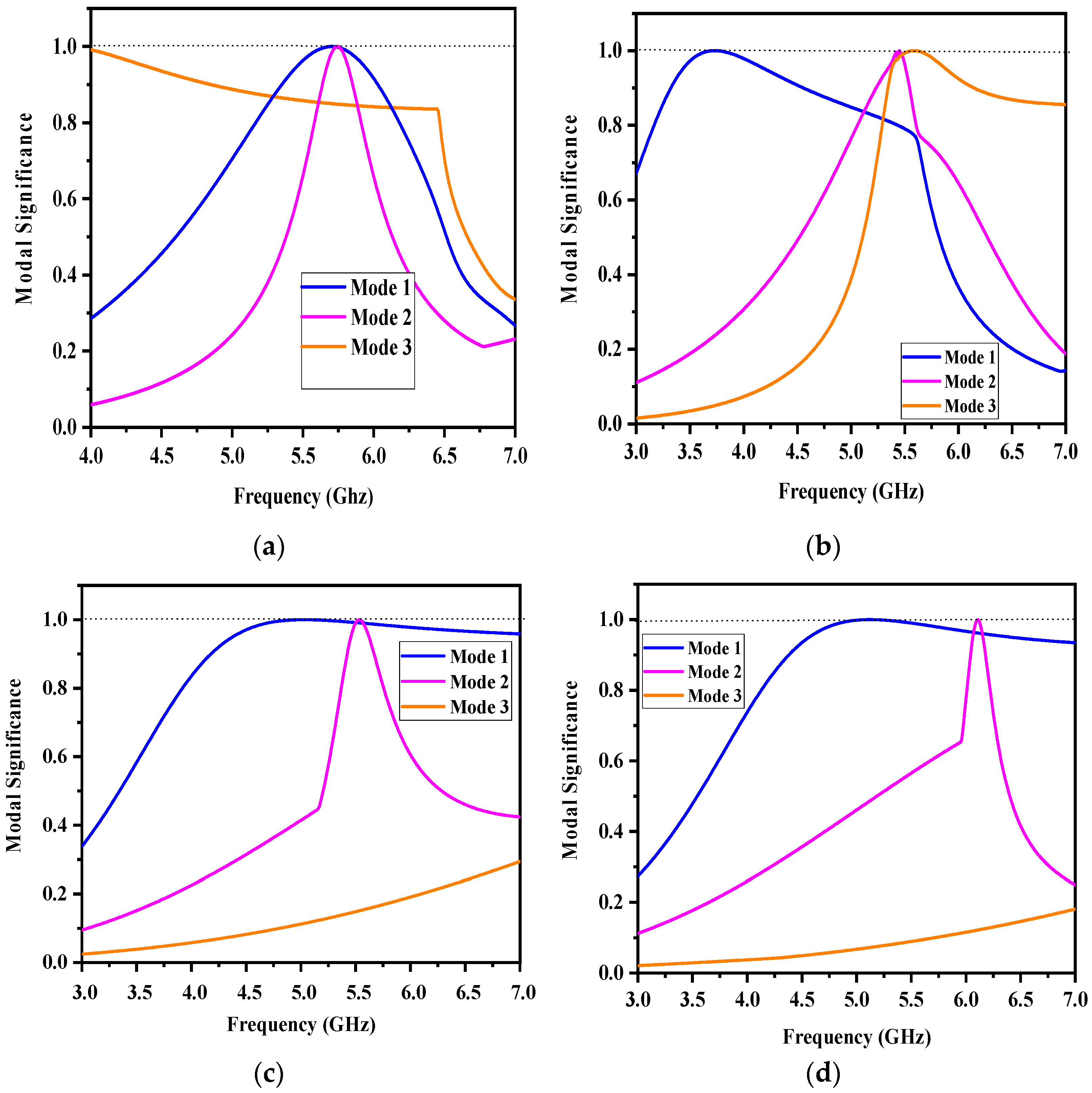
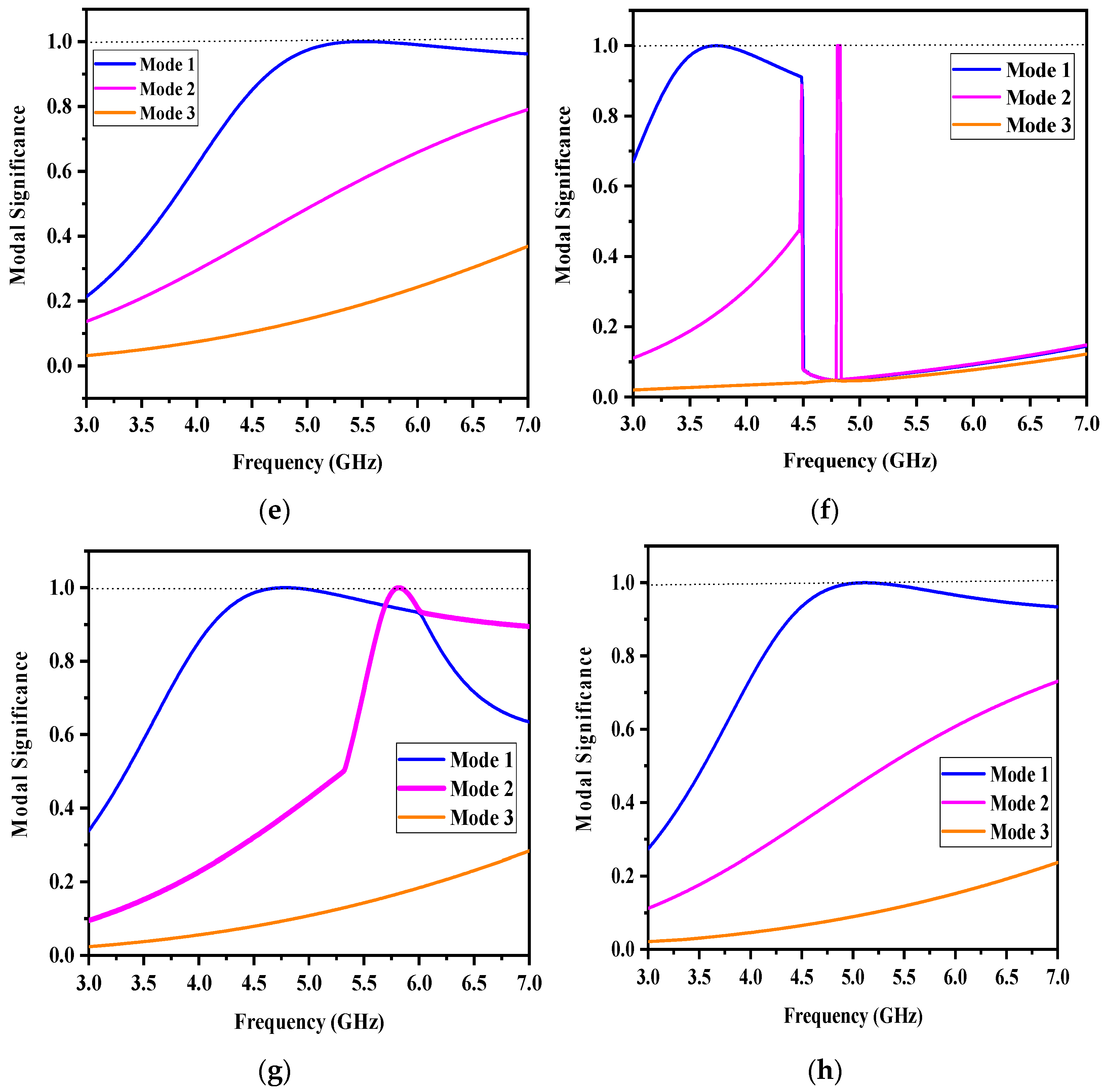
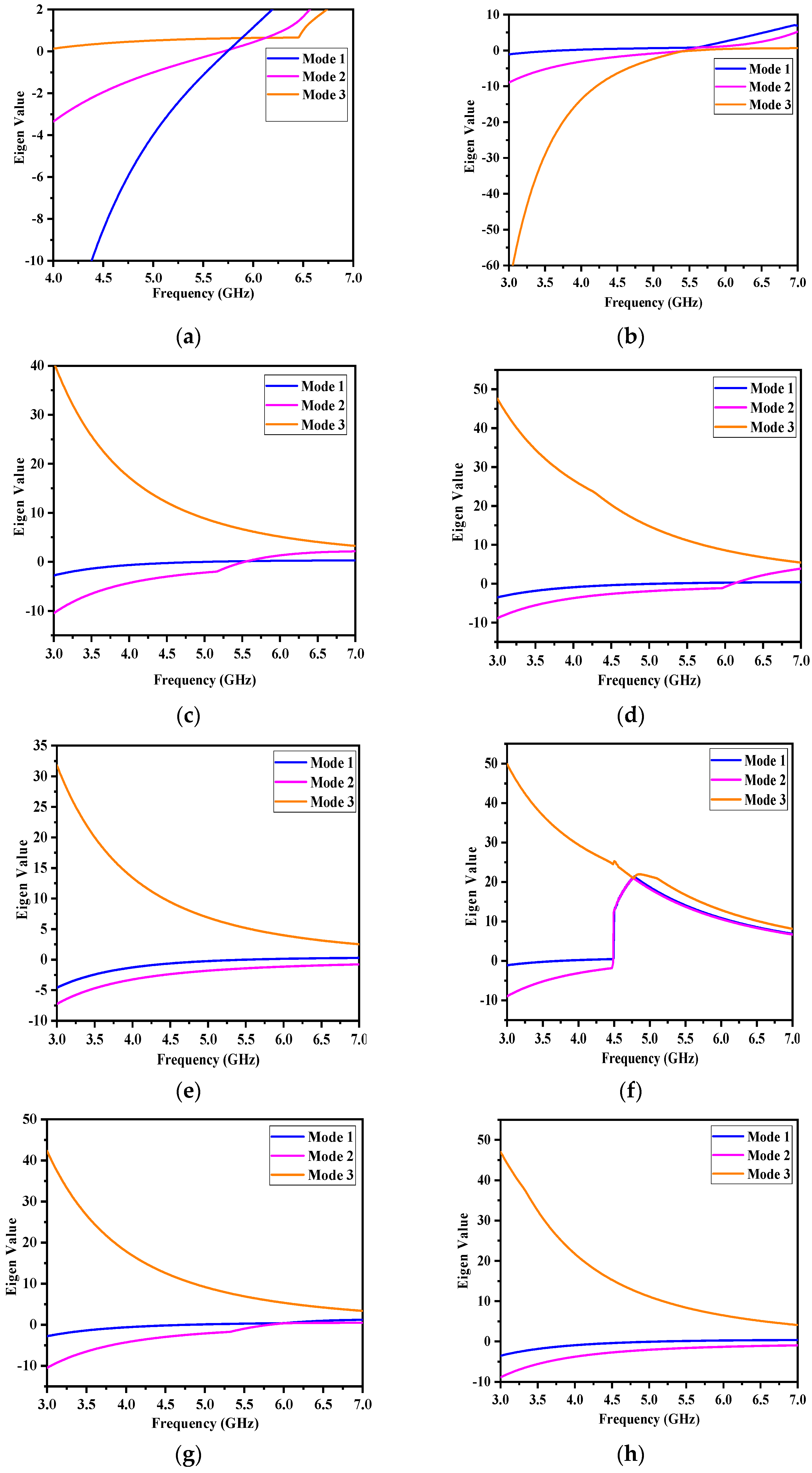
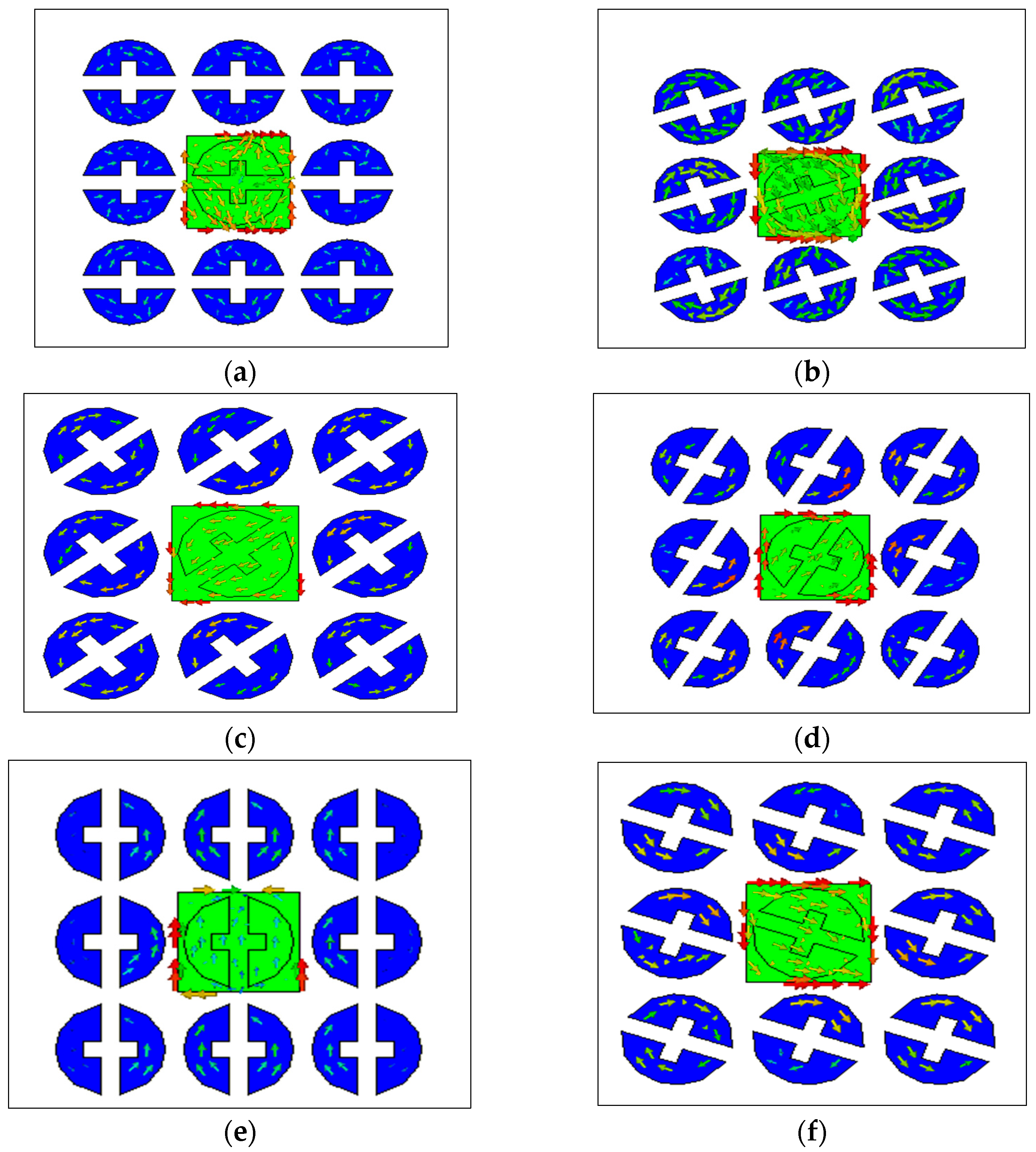
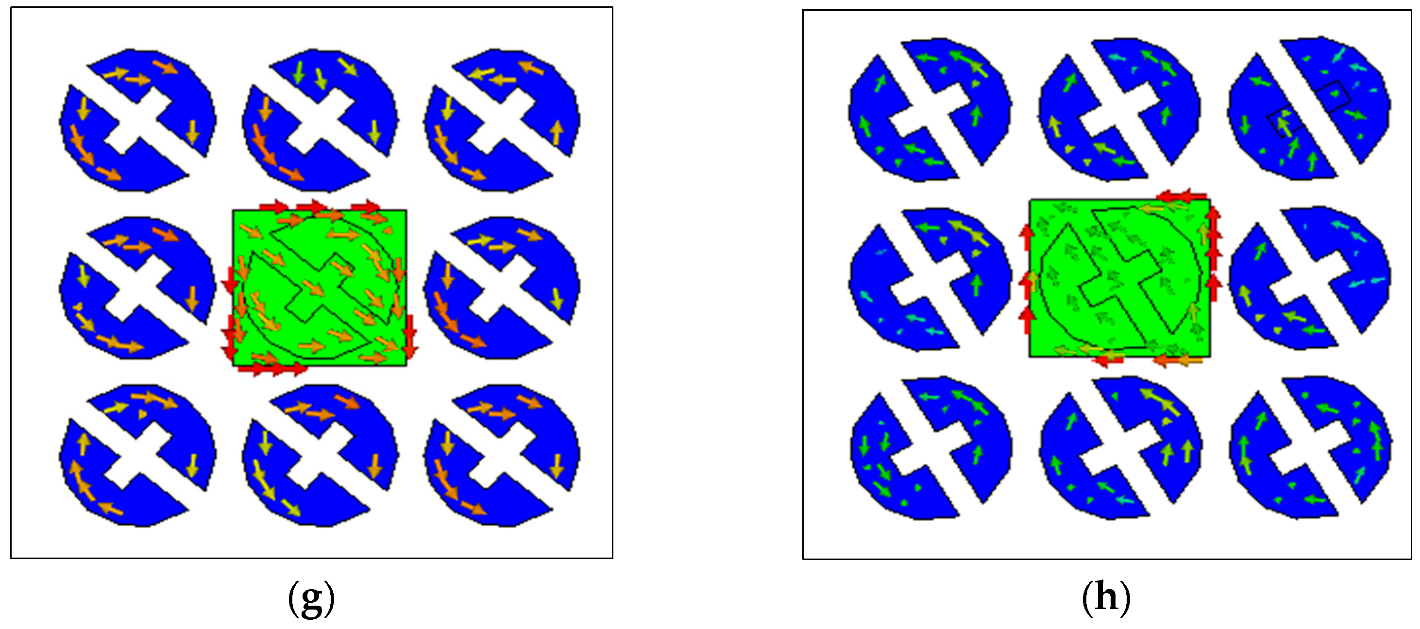
4. Characteristic Mode Analysis
- > 0, the mode is inductive, which means the energy is stored in a magnetic field.
- < 0, the mode is capacitive, which means the energy is stored in an electric field.
- When = 180 deg, the mode is externally resonant.
- When 90 deg < < 180 deg, the mode is inductive.
- When 180 deg < < 180 deg, the mode is capacitive.
5. Conclusions
Author Contributions
Funding
Institutional Review Board Statement
Informed Consent Statement
Data Availability Statement
Acknowledgments
Conflicts of Interest
References
- Chen, S.; Law, R.; Zhang, M.; Si, Y. Mobile Communications for Tourism and Hospitality: A Review of Historical Evolution, Present Status, and Future Trends. Electronics 2021, 10, 1804. [Google Scholar] [CrossRef]
- Alharbi, A.G.; Kulkarni, J.; Desai, A.; Sim, C.-Y.; Poddar, A. A Multi-Slot Two-Antenna MIMO with High Isolation for Sub-6 GHz 5G/IEEE802.11ac/ax/C-Band/X-Band Wireless and Satellite Applications. Electronics 2022, 11, 473. [Google Scholar] [CrossRef]
- Bilal, M.; Naqvi, S.I.; Hussain, N.; Amin, Y.; Kim, N. High-Isolation MIMO Antenna for 5G Millimeter-Wave Communication Systems. Electronics 2022, 11, 962. [Google Scholar] [CrossRef]
- Ferreira-Gomes, B.; Oliveira, O.; Mejía-Salazar, J. Chiral Dielectric Metasurfaces for Highly Integrated, Broadband Circularly Polarized Antenna. Sensors 2021, 21, 2071. [Google Scholar] [CrossRef]
- Gao, G.-P.; Yang, C.; Hu, B.; Wang, S.-F.; Zhang, R.-F. Design of a High-Gain and Low-Profile Quasi-Cassegrain Antenna Based on Metasurfaces. IEEE Antennas Wirel. Propag. Lett. 2018, 17, 1435–1439. [Google Scholar] [CrossRef]
- Tadesse, A.D.; Acharya, O.P.; Sahu, S. Application of metamaterials for performance enhancement of planar antennas: A review. Int. J. RF Microw. Comput. Eng. 2020, 30, e22154. [Google Scholar] [CrossRef]
- Wu, W.; Yuan, B.; Guan, B.; Xiang, T. A bandwidth enhancement for metamaterial microstrip antenna. Microw. Opt. Technol. Lett. 2017, 59, 3076–3082. [Google Scholar] [CrossRef]
- Holloway, C.L.; Kuester, E.F.; Gordon, J.A.; O’Hara, J.; Booth, J.; Smith, D.R. An overview of the theory and applications of metasur-faces: The two-dimensional equivalents of metamaterials. IEEE Antennas Propag. Mag. 2012, 54, 10–35. [Google Scholar] [CrossRef]
- Painam, S.; Bhuma, C. Miniaturizing a Microstrip Antenna Using Metamaterials and Metasurfaces [Antenna Applications Corner]. IEEE Antennas Propag. Mag. 2019, 61, 91–135. [Google Scholar] [CrossRef]
- Zhu, H.; Cao, Y.; Wei, G. Study on non-uniform meta-surface for antenna design. In Proceedings of the IEEE International Conference on Signal Processing, Communications and Computing (ICSPCC), Qingdao, China, 14–16 September 2018; pp. 1–4. [Google Scholar]
- Reis, J.R.; Vala, M.; Oliveira, T.E.; Fernandes, T.R.; Caldeirinha, R.F.S. Metamaterial-Inspired Flat Beamsteering Antenna for 5G Base Stations at 3.6 GHz. Sensors 2021, 21, 8116. [Google Scholar] [CrossRef]
- Bosiljevac, M.; Sipus, Z.; Casaletti, M.; Caminita, F.; Maci, S. Designing horn antennas based on variable metasurface concept. In Proceedings of the 6th European Conference on Antennas and Propagation (EUCAP), Prague, Czech Republic, 26–30 March 2012; pp. 1692–1695. [Google Scholar] [CrossRef]
- Wang, Z.-B.; Wu, H.; Chen, J.-C.; Wu, Z.-H.; Feng, Y.-J. An ultralow-profile lens antenna based on all-dielectric metasurfaces. In Proceedings of the IEEE 5th Asia-Pacific Conference on Antennas and Propagation (APCAP), Kaohsiung, Taiwan, 26–29 July 2016; pp. 367–368. [Google Scholar] [CrossRef]
- Feng, G.; Chen, L.; Xue, X.; Shi, X. Broadband Surface-Wave Antenna With a Novel Nonuniform Tapered Metasurface. IEEE Antennas Wirel. Propag. Lett. 2017, 16, 2902–2905. [Google Scholar] [CrossRef]
- Pan, Y.M.; Hu, P.F.; Zhang, X.Y.; Zheng, S.Y. A Low-Profile High-Gain and Wideband Filtering Antenna with Metasurface. IEEE Trans. Antennas Propag. 2016, 64, 2010–2016. [Google Scholar] [CrossRef]
- Garbacz, R.; Turpin, R. A generalized expansion for radiated and scattered fields. IEEE Trans. Antennas Propag. 1971, 19, 348–358. [Google Scholar] [CrossRef]
- Deng, K.; Yang, F.; Zhou, J.; Lai, C.; Wang, Y.; Han, K. Characteristic Mode Analysis of a Ka-Band CPW-Slot-Couple Fed Patch Antenna with Enhanced Bandwidth and Gain. Electronics 2022, 11, 2395. [Google Scholar] [CrossRef]
- Harrington, R.; Mautz, J.; Chang, Y. Characteristic modes for dielectric and magnetic bodies. IRE Trans. Antennas Propag. 1972, 20, 194–198. [Google Scholar] [CrossRef]
- Zhang, Q.; Ma, R.; Su, W.; Gao, Y. Design of a Multimode UWB Antenna using Characteristic Mode Analysis. IEEE Trans. Antennas Propag. 2018, 66, 3712–3717. [Google Scholar] [CrossRef]
- Kumar, O.P.; Kumar, P.; Ali, T.; Kumar, P.; Vincent, S. Ultrawideband Antennas: Growth and Evolution. Micromachines 2022, 13, 60. [Google Scholar] [CrossRef]
- Ni, C.; Wen, B.; Wu, W.; Ren, P. Wideband Filtering Slot Antenna Design with Stable Gain Using Characteristic Mode Analysis. Sensors 2022, 22, 2780. [Google Scholar] [CrossRef]
- Perli, B.R.; Avula, M.R. Design of Wideband Elliptical Ring Monopole Antenna using Characteristic Mode Analysis. J. Electromagn. Eng. Sci. 2021, 21, 299–306. [Google Scholar] [CrossRef]
- Santill’an-Haro, D.; Daviu, E.A.; Escuderos, D.S.; Bataller, M.F. Analysis and design of a metamaterial lens antenna using the theory of characteristic modes. Int. J. Antennas Propag. 2018, 2018, 6329531. [Google Scholar] [CrossRef]
- Nkimbeng, C.H.S.; Wang, H.; Park, I. Coplanar Waveguide-Fed Bidirectional Same-Sense Circularly Polarized Metasurface-Based Antenna. J. Electromagn. Eng. Sci. 2021, 21, 210–217. [Google Scholar] [CrossRef]
- Lin, F.H.; Chen, Z.N. Truncated Impedance Sheet Model for Low-Profile Broadband Nonresonant-Cell Metasurface Antennas Using Characteristic Mode Analysis. IEEE Trans. Antennas Propag. 2018, 66, 5043–5051. [Google Scholar] [CrossRef]
- Juan, Y.; Yang, W.; Che, W. Miniaturized Low-Profile Circularly Polarized Metasurface Antenna Using Capacitive Loading. IEEE Trans. Antennas Propag. 2019, 67, 3527–3532. [Google Scholar] [CrossRef]
- Zhao, C.; Wang, C.-F. Characteristic Mode Design of Wide Band Circularly Polarized Patch Antenna Consisting of H-Shaped Unit Cells. IEEE Access 2018, 6, 25292–25299. [Google Scholar] [CrossRef]
- Li, T.; Chen, Z.N. A Dual-Band Metasurface Antenna Using Characteristic Mode Analysis. IEEE Trans. Antennas Propag. 2018, 66, 5620–5624. [Google Scholar] [CrossRef]
- Vogel, M.; Gampala, G.; Ludick, D.; Reddy, C.J. Characteristic Mode Analysis: Putting Physics back into Simulation. IEEE Antennas Propag. Mag. 2015, 57, 307–317. [Google Scholar] [CrossRef]
- Harrington, R.; Mautz, J. Computation of characteristic modes for conducting bodies. IEEE Trans. Antennas Propag. 1971, 19, 629–639. [Google Scholar] [CrossRef]
- Chen, Y.; Wang, C. Characteristic Modes Theory Applications in Antenna Engineering; John Wiley & Sons: Hoboken, NJ, USA, 2015. [Google Scholar]
- Hussain, N.; Jeong, M.-J.; Abbas, A.; Kim, T.-J.; Kim, N. A Metasurface-Based Low-Profile Wideband Circularly Polarized Patch Antenna for 5G Millimeter-Wave Systems. IEEE Access 2020, 8, 22127–22135. [Google Scholar] [CrossRef]
- Kang, E.; Hur, J.; Seo, C.; Lee, H.; Choo, H. High Aperture Efficiency Array Antenna for Wireless Power Transfer Applications. Energies 2020, 13, 2241. [Google Scholar] [CrossRef]
- Gao, G.; Zhang, R.-F.; Geng, W.-F.; Meng, H.-J.; Hu, B. Characteristic Mode Analysis of a Nonuniform Metasurface Antenna for Wearable Applications. IEEE Antennas Wirel. Propag. Lett. 2020, 19, 1355–1359. [Google Scholar] [CrossRef]
- Hamad, E.K.I.; Abdelaziz, A. Metamaterial superstrate microstrip patch antenna for 5G wireless communication based on the theory of characteristic modes. J. Electr. Eng. 2019, 70, 187–197. [Google Scholar] [CrossRef]


| R | h | Lp | Wp | r | Ws | Lc | Wc | Ө | Uw | UL |
|---|---|---|---|---|---|---|---|---|---|---|
| 27.5 | 2 | 13.27 | 13 | 6 | 2 | 2 | 2 | 40° | 14 | 14 |
| Angle | Ө = 0° | Ө = 20° | Ө = 40° | Ө = 60° | Ө = 90° | Ө = −20° | Ө = −40° | Ө = −60° |
|---|---|---|---|---|---|---|---|---|
| Mode 1 | 5.6 | 3.7 | 5.0 | 5.0 | 5.49 | 3.7 | 4.7 | 5.09 |
| Mode 2 | 5.7 | 5.4 | 5.5 | 6.1 | - | 4.48 | 5.8 | - |
| Mode 3 | - | 5.6 | - | - | - | - | - | - |
| Modal Significance (MS = 1) | Ө = 0° | Ө = 20° | Ө = 40° | Ө = 60° | Ө = 90° | Ө = −20° | Ө = −40° | Ө = −60° |
|---|---|---|---|---|---|---|---|---|
| Mode 1 | 5.6 | 3.7 | 5.0 | 5.0 | 5.49 | 3.7 | 4.7 | 5.09 |
| Mode 2 | 5.7 | 5.4 | 5.5 | 6.1 | - | 4.48 | 5.8 | - |
| Mode 3 | - | 5.6 | - | - | - | - | - | - |
| Eigenvalue ( | Ө = 0° | Ө = 20° | Ө = 40° | Ө = 60° | Ө = 90° | Ө = −20° | Ө = −40° | Ө = −60° |
|---|---|---|---|---|---|---|---|---|
| Mode 1 | 5.6 | 3.7 | 5.0 | 5.0 | 5.49 | 3.7 | 4.7 | 5.09 |
| Mode 2 | 5.7 | 5.4 | 5.5 | 6.1 | - | 4.48 | 5.8 | - |
| Mode 3 | - | 5.6 | - | - | - | - | - | - |
| Reference | Dimensions (mm × mm) | Bandwidth (GHz) | Average Gain (dBi) | Average Efficiency |
|---|---|---|---|---|
| [5] | 132 × 132 | 5.71–5.88 | 13.7 | NR |
| [15] | 78 × 78 | 4.20–5.59 | 8.2 | 95% |
| [32] | 80 × 60 | 3.27–4.66 | 7.7 | NR |
| [33] | 60 × 60 | 4.9–5.1 | 11.6 | NR |
| [34] | 27.5 × 27.5 × π | 5.07–5.94 | 7.63 | >80% |
| [35] | 20 × 20 | 9.798–10.202 14.09–15.91 | 8.24 9.65 | 82% 87% |
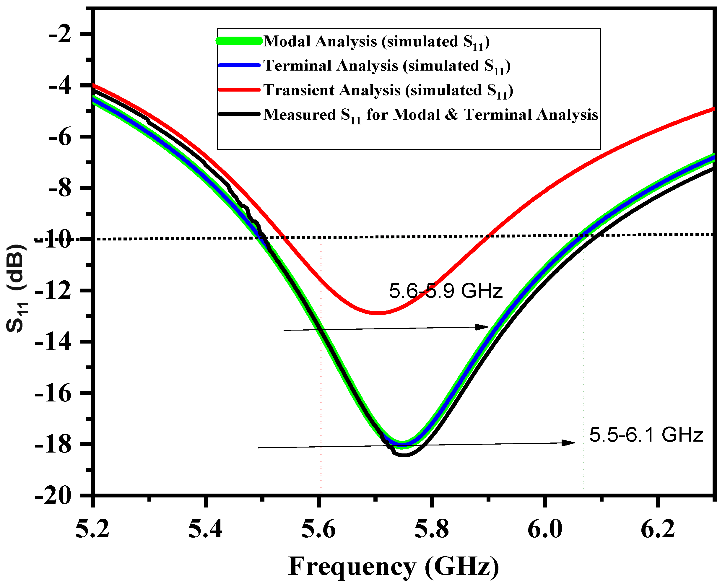
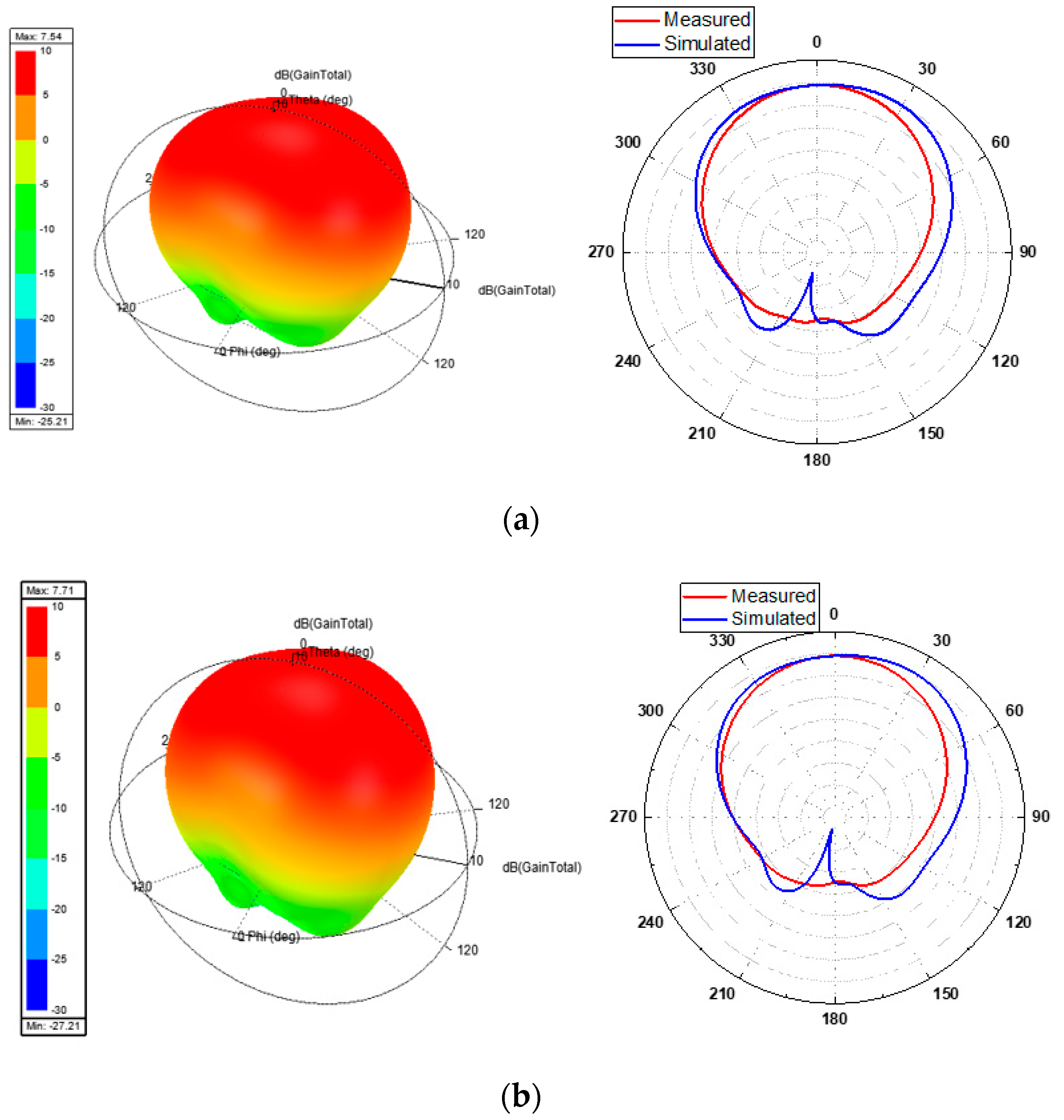
| Proposed | 27.52 × π | 5.5–6.1 | 7.9 | >90% |
Publisher’s Note: MDPI stays neutral with regard to jurisdictional claims in published maps and institutional affiliations. |
© 2022 by the authors. Licensee MDPI, Basel, Switzerland. This article is an open access article distributed under the terms and conditions of the Creative Commons Attribution (CC BY) license (https://creativecommons.org/licenses/by/4.0/).
Share and Cite
Bhavani, K.D.; Madhav, B.T.P.; Das, S.; Hussain, N.; Ali, S.S.; Babu, K.V. Development of Metamaterial Inspired Non-Uniform Circular Array Superstate Antenna Using Characteristic Mode Analysis. Electronics 2022, 11, 2517. https://doi.org/10.3390/electronics11162517
Bhavani KD, Madhav BTP, Das S, Hussain N, Ali SS, Babu KV. Development of Metamaterial Inspired Non-Uniform Circular Array Superstate Antenna Using Characteristic Mode Analysis. Electronics. 2022; 11(16):2517. https://doi.org/10.3390/electronics11162517
Chicago/Turabian StyleBhavani, Kothakonda Durga, Boddapati Taraka Phani Madhav, Sudipta Das, Niamat Hussain, Syed Samser Ali, and Kommanaboyina Vasu Babu. 2022. "Development of Metamaterial Inspired Non-Uniform Circular Array Superstate Antenna Using Characteristic Mode Analysis" Electronics 11, no. 16: 2517. https://doi.org/10.3390/electronics11162517
APA StyleBhavani, K. D., Madhav, B. T. P., Das, S., Hussain, N., Ali, S. S., & Babu, K. V. (2022). Development of Metamaterial Inspired Non-Uniform Circular Array Superstate Antenna Using Characteristic Mode Analysis. Electronics, 11(16), 2517. https://doi.org/10.3390/electronics11162517