Article

High-Efficiency Power Optimization Based on Reconfigurable Intelligent Surface for Nonlinear SWIPT System

1
College of Information Engineering, Shenzhen University, Shenzhen 518060, China
2
School of Microelectronics, Shenzhen Institute of Information Technology, Shenzhen 518109, China
*
Author to whom correspondence should be addressed.
Electronics 2022, 11(17), 2681; https://doi.org/10.3390/electronics11172681
Submission received: 11 July 2022 / Revised: 16 August 2022 / Accepted: 24 August 2022 / Published: 26 August 2022

Abstract

:
This paper presents an investigation of the transmitting power consumption of a base station (BS) in a simultaneous wireless information and power transfer (SWIPT) system enhanced by a reconfigurable intelligent surface (RIS). The aim is to optimize the total transmitting power consumption when sending information signals and energy from the BS to ground sensors. To this end, the transmitting power consumption of the BS is optimized by satisfying the sensor’s minimum signal-to-interference-plus-noise ratio (SINR), the phase shift constraints of the RIS, and each sensor’s power-splitting (PS) ratio. In order to decouple the optimization variables, we use the technique of block coordinate descent (BCD) to transform the total problem into subproblems. In the second subproblem, the unit modulus constraints are approximated using the successive convex approximation (SCA) method, allowing the optimal solutions to be obtained by solving subproblems in an iterative manner. Our numerical simulation results show that transmitting power consumption can be significantly decreased by adding RIS to an SPWIT system, even in nonlinear harvest models of real application scenarios.

1. Introduction

Today, the era of data explosion has permeated in all walks of life, causing rapidly growing demand for various kinds of wireless sensor devices and corresponding application data communications. The emerging need to increase wireless systems’ spectral and energy efficiency is becoming one of the most important contemporary research topics, and appears to require the integration of multiple effective techniques [1]. Among the newest communication technologies, reconfigurable intelligent surfaces (RIS) have received a great deal of attention from researchers [2,3,4,5]. An RIS is comprised of reflecting elements that can reshape the transmission path of wireless signals by adjusting the reflection coefficient. Compared to traditional relaying, RIS usage can effectively improve the transmission environment by adding extra communication channels with limited power, or even totally passive ones. Hence, it is considered a promising technique for achieving controllable communication propagation environments as well as an effective solution for realizing higher SE and EE for future wireless communication systems.
Though mobile devices are designed for various applications, the equipped battery limits their working time. Therefore, different kinds of energy harvesting (EH) techniques have been proposed as promising solutions for prolonging the lifetime of such devices [6,7,8,9,10]. Among these, the simultaneous wireless information and power transfer (SWIPT) technique, which enables sensors to simultaneously obtain energy signals and information from transmitted signals, has been studied in many previous works [11,12,13,14,15,16]. To further improve the SWIPT system’s performance, several existing works have attempted to integrate it with RIS. For example, in [2,4,5], the authors discussed the performance of separated EH and information harvested (IH) devices in an RIS-assisted SWIPT system with a linear EH model. Specifically, the EE maximization problem was discussed by optimizing beamforming vectors of the base station (BS), each user’s power-splitting (PS) ratio, and RIS phase shifts under the condition of minimum quality of service (QoS) for every user and phase shift constraints for RIS. However, these works only considered linear EH models in the energy harvesting process, which is significantly inaccurate when considering practical application scenarios [17].
In this paper, the total transmitting power consumption optimization problem is investigated in an RIS-aided nonlinear SWIPT system. The aim is to optimize the base station’s transmitting power consumption by satisfying the sensor’s minimum signal-to-interference-plus-noise ratio (SINR), each sensor’s PS ratio, the minimum EH requirement, and the unit-modulus constraints of the RIS. In terms of implementation, we use the method of block coordinate descent (BCD) to decouple the total problem into subproblems. Furthermore, the semi-definite relaxation (SDR) method along with successive convex approximation are used in each subproblem to transform them into convex problems. Finally, optimal solutions for the original problem are obtained using the alternate optimization framework.
The subsections of this work are arranged as follows. Models of RIS-aided SWIPT and nonlinear energy harvesting are presented in Section 2. In Section 3, we formulate the transmitting power consumption optimization problem and investigate the process for solving it. The results of algorithmic simulations used to verify the developed algorithms’ effectiveness are described in Section 4. We present the conclusions drawn from this work in Section 5.

2. System Model

A downlink RIS-aided SWIPT system with a BS consisting of M antennas, K single-antenna sensors, and an RIS with N reflecting elements is constructed in this section, as shown in Figure 1. The transmission of signals from the BS to the sensors can be enhanced by the deployment of the RIS. Specifically, in a SWIPT system, all users can obtain both energy and information signals from the BS. However, due to the complex communication environment, certain users are located far away from BS or are obstructed by obstacles. These users cannot fully realize the transmission of their information or the harvesting of energy from the BS. Hence, by deploying an RIS in the SWIPT system we can enhance the signals transmitted from the BS. The RIS can effectively reflect the incident signals to users by carefully revising the related parameters, and can be used either totally passively or at very low power. This is very helpful for the communication system, as it provides extra communication channels and can control the signal transmitting environment. Furthermore, we assume all sensors in the SWIPT system adopt PS to divide the received signal for energy harvesting and information decoding (ID).

2.1. Transmission Scheme

In a SWIPT system, the BS is designed for simultaneous wireless information signal and power signal transfer. Hence, the BS transmission signal can be modeled as
x = i = 1 K w i s i + v e ,
where w i C M × 1 denotes the ith sensor’s beamforming vector; s i CN ( 0 , 1 ) is the intended signal for the ith sensor, which conforms to the complex Gaussian distribution and has a mean and variance of 0 and 1, respectively; v e denotes the energy beamforming vector to enable the sensors performing energy-harvesting, which is assumed to be a Gaussian pseudo-random sequence for which the mean is 0 and the covariance matrix is V e H M , V e 0 , i.e., v e CN ( 0 , V e ) . The diagonal reflection coefficient matrix is defined as Φ = diag { e j θ 1 , , e j θ i , , e j θ N } , where the phase of the RIS reflecting element is denoted as θ i . The communication channels from the BS to the kth sensor, the BS to the added RIS, and the added RIS to the sensor are represented by h b , k C M × 1 , H C N × M , and h r , k C N × 1 , respectively. The set of sensors is defined as K = { 1 , 2 , , K } . Furthermore, the signal received by the kth sensor can be obtained by
y k = i = 1 K h k H w i s i + h k H v e + z k , k K ,
where h k H = h r , k H Φ H + h b , k H , z k CN ( 0 , σ 2 ) is the Gaussian noise received by the kth sensor. The signal received by the kth user equipment (UE) is divided into two portions; the ρ k part is for information decoding, while the 1 ρ k part is for energy harvesting. Therefore, the signals for the ID of the kth UE are provided by
y k I D = ρ k y k + n k ,
where n k CN ( 0 , δ k 2 ) represents the Gaussian noise caused by the ID module’s circuit.
The EH modules’ signals received by the kth sensor are provided by
y k E H = 1 ρ k y k .
Hence, the received SINR at the kth sensor can be obtained by
SINR k = | h k H w k | 2 i = 1 , i k K | h k H w i | 2 + | h k H v e | 2 + σ 2 + δ k 2 / ρ k , k K .

2.2. Non-Linear EH Model

In most previous research [18,19,20,21], the energy harvested by the kth sensor has been determined by the following linear model:
Φ E H k L = η k P E H k L , P E H k L = ( 1 ρ k ) i = 1 K Tr ( H k W i ) + Tr ( H k V e ) ,
where H k = h k h k H , V e = v e v e H , P E H k L denotes the input power of the energy harvesting module, and 0 η k 1 denotes the range of the fixed conversion efficiency of the kth sensor. In order to utilize this model with nonlinear energy harvesting, we set η k = 1 for all sensors. It is easy to determine that the total harvested energy in the linear model is proportional to the kth sensor’s received signal power in a linear manner. Moreover, the linear model is accurate only when the kth sensor’s received signal power is constant. However, practical energy harvesting modules realize the power transfer in a nonlinear manner.
Hence, using the linear model in wireless energy harvesting designs may cause suboptimal resource allocation or poor system performance, and cannot be applied in reality. A nonlinear energy harvesting model can avoid mismatches caused by the traditional linear model [22,23]. Therefore, a nonlinear model is adopted here to characterize the wireless power transfer at the sensor in the SWIPT system, which is provided by [17]
Φ E H k N L = Ψ E H k N L M i Ω i 1 Ω i , Ω i = 1 1 + exp ( a i b i ) ,
Ψ E H k N L = M i 1 + exp ( a i ( P E H k L b i ) ) ,
where Ψ E H k N L denotes the logistic function with respect to the received signal power P E H k L and Ω i , M i , a i , and b i are constants used to characterize the joint effects of various hardware constraints. In practice, each sensor’s energy harvesting circuit is fixed, and the value of parameters M i , a i , and b i can be easily found through methods such as a standard curve fitting tool.

3. Problem Formulation and Solution

In this section, we investigate the optimization problem of minimizing the total transmitting power of the BS by satisfying the minimum SINR, minimum harvested power of each sensor, and unit module requirements for the RIS. The BCD technique is adopted to deal with coupled variables and the solutions are then obtained in an iterative manner.

3.1. Problem Formulation

The total transmitting power consumption of the BS is minimized by satisfying the power splitting ratio constraint, the minimum SINR, and the harvesting energy requirement of each sensor. In this optimization problem, the BS beamforming matrix, the PS ratio, and the phase shifts of the reflecting elements all need to be optimized. The total problem can be formulated as follows:   
P 0 : min W , ρ , ϕ , V e i = 1 K Tr ( W k ) + Tr ( V e )
s . t . | h k H w k | 2 i = 1 , i k K | h k H w i | 2 + | h k H v e | 2 + σ 2 + δ k 2 / ρ k γ k , k K ,
Φ E H k N L e k , k K ,
0 < ρ k < 1 , k K ,
| ϕ n | , n N ,
V e 0 , W k 0 , k K ,
where W k = w k w k H , W = [ W 1 , , W K ] , ϕ = [ ϕ 1 , , ϕ N ] collects the diagonal elements of matrix Φ , ϕ i = e j θ i , ρ = [ ρ 1 , , ρ K ] is the PS ratio vector, and γ k and e k are the minimum SINR and harvested power requirements for the kth sensor, respectively.

3.2. Problem Transformation and Solution Procedure

It is challenging to solve this problem directly because of the non-convex constraints and coupled variables. Therefore, we exploit the BCD technique to transform the problem into two subproblems. The solutions of the original problem can then be obtained by alternately optimizing these subproblems.

3.2.1. Optimizing W , ρ , and V e with a Given ϕ

When this problem is written with fixed phase shifts ϕ , the BS beamforming matrix, PS ratio, and energy beamforming matrix need to be optimized. Problem (9) can be simplified as
P 1 : min W , ρ , V e i = 1 K Tr ( W k ) + Tr ( V e )
s . t . Tr ( H k W k ) γ k i = 1 , i k K Tr ( H k W i ) Tr ( H k V e ) σ 2 + δ k 2 ρ k ,
Φ E H k N L e k , k K ,
0 < ρ k < 1 , k K ,
V e 0 , W k 0 , Rank ( W k ) 1 , k K .
where Rank ( W k ) 1 is added to guarantee optimal beamforming vectors; w k can always be recovered through eigenvalue decomposition of the optimal W k .
It remains hard to solve this problem because of the non-convex constraints, as shown in (11). Note that Ω k does not have a relationship with the optimization problem; we use Ψ E H k N L to directly describe the harvested power at the kth sensor. Hence, we can find the relationship between the nonlinear and linear harvested power based on (8), which is modeled as
P E H k L ( Ψ E H k N L ) = b i 1 a i ln M i Ψ E H k N L 1 .
Therefore, constraints (12) can be rewritten as
( 1 ρ k ) i = 1 K Tr ( H k W i ) + Tr ( H k V e ) P E H k L ( e k ) ,
where P E H k L ( e k ) is known due to the minimum harvested power e k and the other parameters are constants.
Then, Problem P 1 can be transformed as follows:
P 2 : min W , ρ , V e i = 1 K Tr ( W k ) + Tr ( V e )
s . t . V e 0 , W k 0 , k K ,
(11) , (13) , (16) .
This problem is convex, and a semi-definite program (SDP) can be used to obtain the optimal solutions. Specifically, we know that the constraints (11) and (13) are linear with ρ k and the constraints in (18) are convex positive semi-definite matrices. Hence, Problem P 2 is a standard SDP and the CVX toolbox can be adopted to solve it. Furthermore, the optimal solution of Problem P 2 satisfies the rank-one constraints for all W k [24]. Then, the optimal beamforming vector w k * can be obtained by performing eigenvalue decomposition for the optimal W k * , meaning that the complexity of solving Problem P 2 is O ( K M ( K 3 M 2 + K 2 M 3 ) ) [25].

3.2.2. Optimizing ϕ with Fixed W , ρ , and V e

With a given W , ρ , and V e , the objective function of Problem P 0 has no relationship with a variable ϕ . Hence, it becomes a feasibility check problem with non-convex constraints. If we define ϕ ˜ = [ ϕ H 1 ] , T k = [ diag { h r , k H } H ; h b , k H ] , then we have
Tr ( H k W k ) = Tr ( Φ ˜ T k W k T k H ) ,
where Φ ˜ = ϕ ˜ H ϕ ˜ .
Therefore, Problem P 0 can be transformed as follows:
P 3 : Find Φ ˜ Φ ˜
s . t . Tr ( Φ ˜ T k ( W k / γ k V e ) T k H ) i = 1 , i k K Tr ( Φ ˜ T k W i T k H ) σ 2 + δ k 2 ρ k , k K ,
( 1 ρ k ) i = 1 K Tr ( Φ ˜ T k W i T k H ) + Tr ( Φ ˜ T k V e h ˜ k H ) P E H k L ( e k ) ,
diag { Φ ˜ } = 1 N + 1 , Φ ˜ 0 ,
Rank ( Φ ˜ ) = 1 .
It remains hard to solve the problem because of the non-convex constraint Rank ( Φ ˜ ) = 1 . To tackle this problem, a penalty-based algorithm can be used to replace the rank-one constraint with its approximated form. Because Φ ˜ is a positive semi-definite (PDS) matrix, Tr ( Φ ˜ ) λ m a x ( Φ ˜ ) holds. Moreover, if Tr ( Φ ˜ ) = 1 , we have Tr ( Φ ˜ ) = λ m a x ( Φ ˜ ) . Problem P 3 can thus be reformulated as
P 4 : min Tr ( Φ ˜ ) λ m a x ( Φ ˜ )
s . t . (21) (23) ,
Because Problem P 4 ’s objective function is non-convex, an iterative method is adopted to solve the non-convex part. With a feasible point Φ ˜ ( t ) in the tth iteration, we have
Tr ( Φ ˜ ( t + 1 ) ) ( e ( t ) ) H Φ ˜ ( t + 1 ) ( e ( t ) ) Tr ( Φ ˜ ( t + 1 ) ) λ m a x ( Φ ˜ ( t + 1 ) ) ,
where e ( t ) is the unit eigenvector with respect to the maximum eigenvalue, λ m a x ( Φ ˜ ( t ) ) .
Therefore, Problem P 4 in the ( t + 1 ) th iteration is written as
P 5 : min Φ ˜ ( t + 1 ) Tr ( Φ ˜ ( t + 1 ) ) ( e ( t ) ) H Φ ˜ ( t + 1 ) ( e ( t ) )
s . t . (21) (23) ,
Following the above investigation, the penalty-based algorithm used to obtain the solution to Problem P 5 is presented in Algorithm  1.
Algorithm 1 Penalty-based algorithm for optimizing reflecting beamforming of RIS.
  • Require:
  •     Initialization initialize feasible Φ ˜ 0 , penalty factor η 0 , convergence tolerance ϵ , the
  •      maximum iteration number T m a x , and the iteration number t = 1 .
  • Ensure: 
  •     Repeat
  •      Obtain Φ ˜ t by solving Problem P 5 ;
  •      if  Tr ( Φ ˜ t ) λ m a x ( Φ ˜ t ) < ϵ  then
  •          break;
  •      else
  •          Update e ( t ) and t = t + 1 ;
  •       end if
  •   Until convergence or t > T m a x .
This algorithm mainly uses the interior point method; the computational complexity in each iteration is expressed as O log 1 ρ K M 7 2 + N 7 2 .
The overall alternating algorithm used to solve Problem P 0 is shown in Algorithm  2.
Algorithm 2 Alternating algorithm for minimizing transmit power consumption of BS.
  • Require: 
  •     Initialization initialize feasible Φ ˜ 0 , the maximum iteration number T m a x , and the iteration number t = 0 .
  • Ensure: 
  •     Repeat
  •      According to given ϕ , update W , ρ and V e by obtaining the optimal solution of
  •      Problem P 2 ;
  •      With obtained W ( t ) , ρ ( t ) and V e ( t ) , update Φ ˜ ( t + 1 ) by using Algorithm  1;
  •      Obtain ϕ ( t + 1 ) by using eigenvalue decomposition for Φ ˜ ( t + 1 ) ; t = t + 1 ;
  • Until convergence or t > T m a x .
In this algorithm, both of the subproblems of P 2 and P 5 can obtain the stationary points. Hence, Algorithm 2 is guaranteed to be able to converge on a stationary point in problem P 0 [26]. The computational complexity of the algorithm is O ln 1 ρ K 2 ( M N ) 7 2 + L ( K N 7 2 + K 2 N 5 2 ) , where ρ denotes the tolerance parameter of using interior point method and L denotes the iteration number of Algorithm 1.

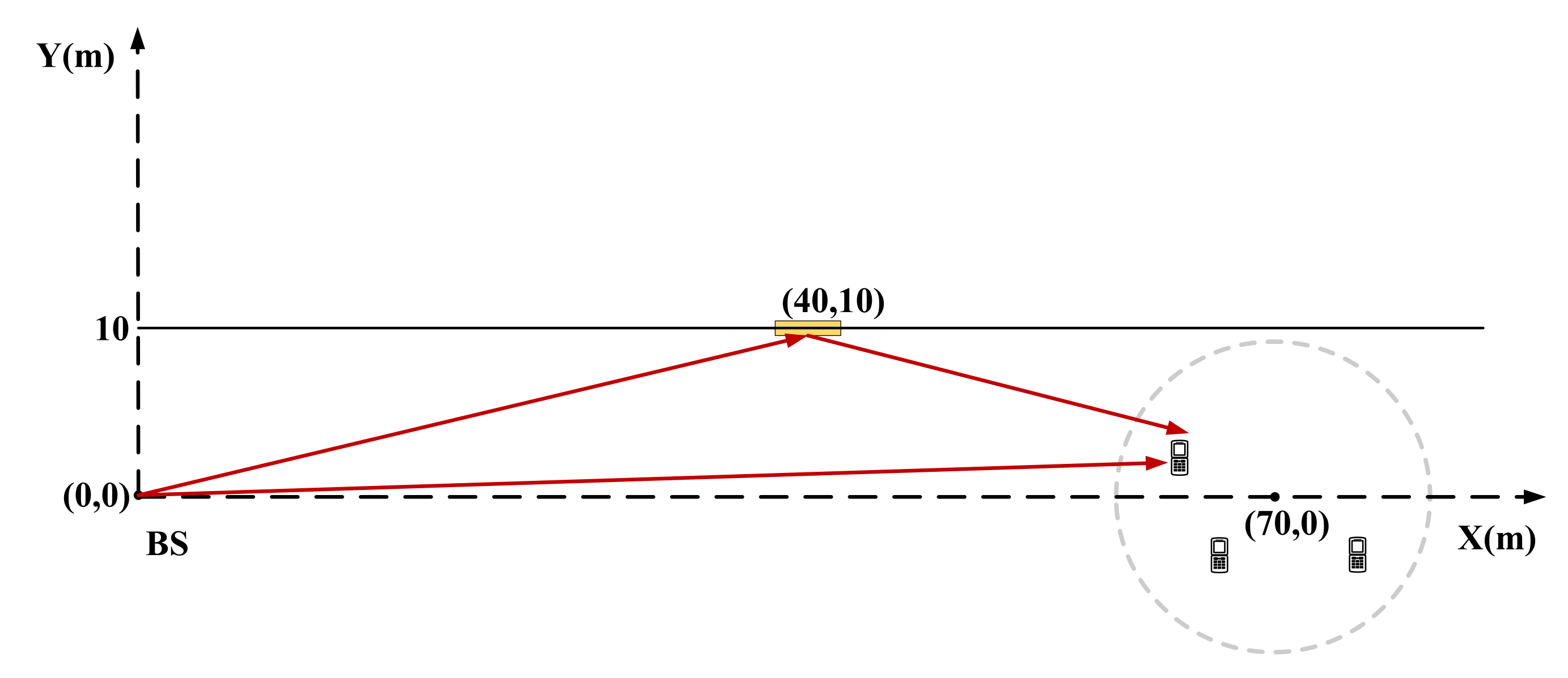
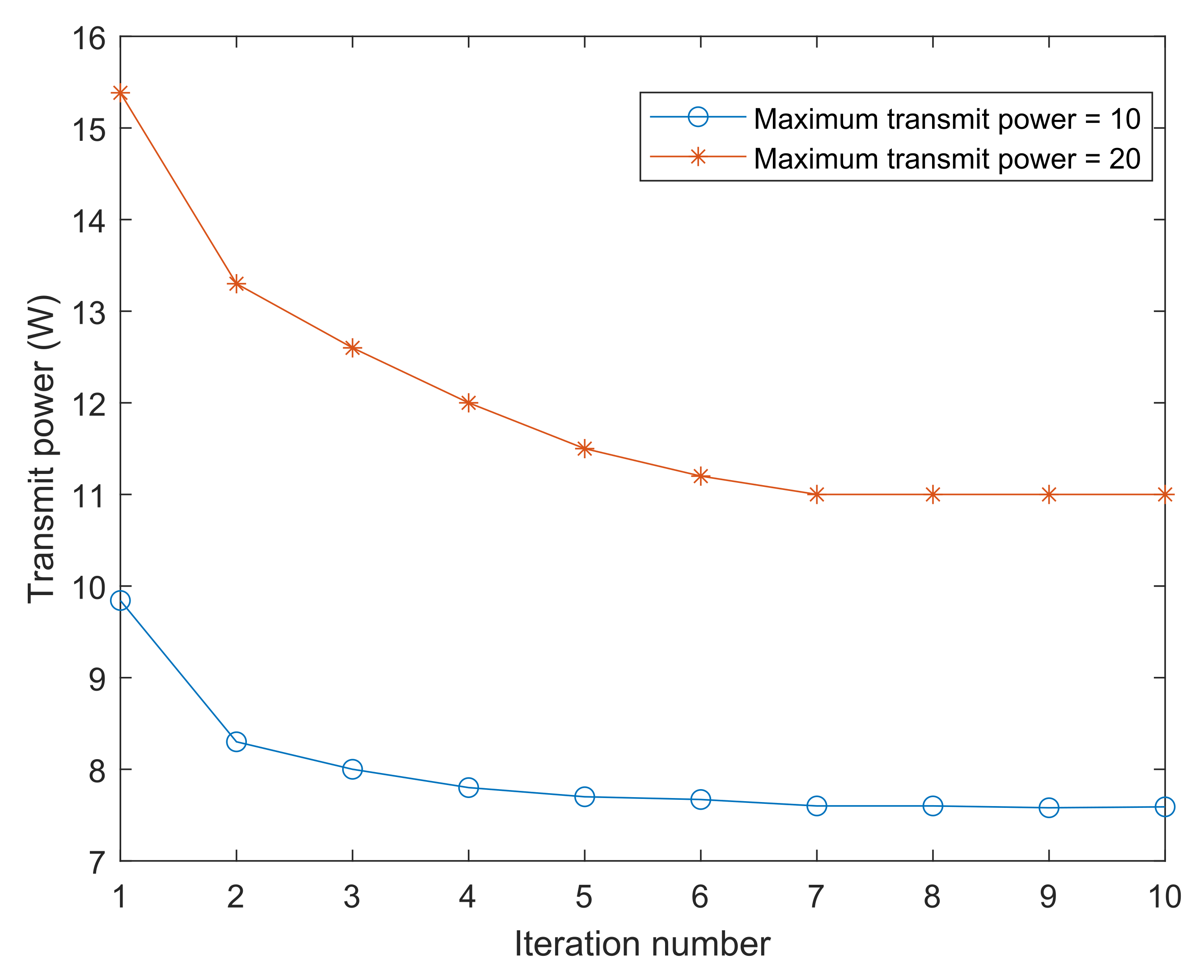
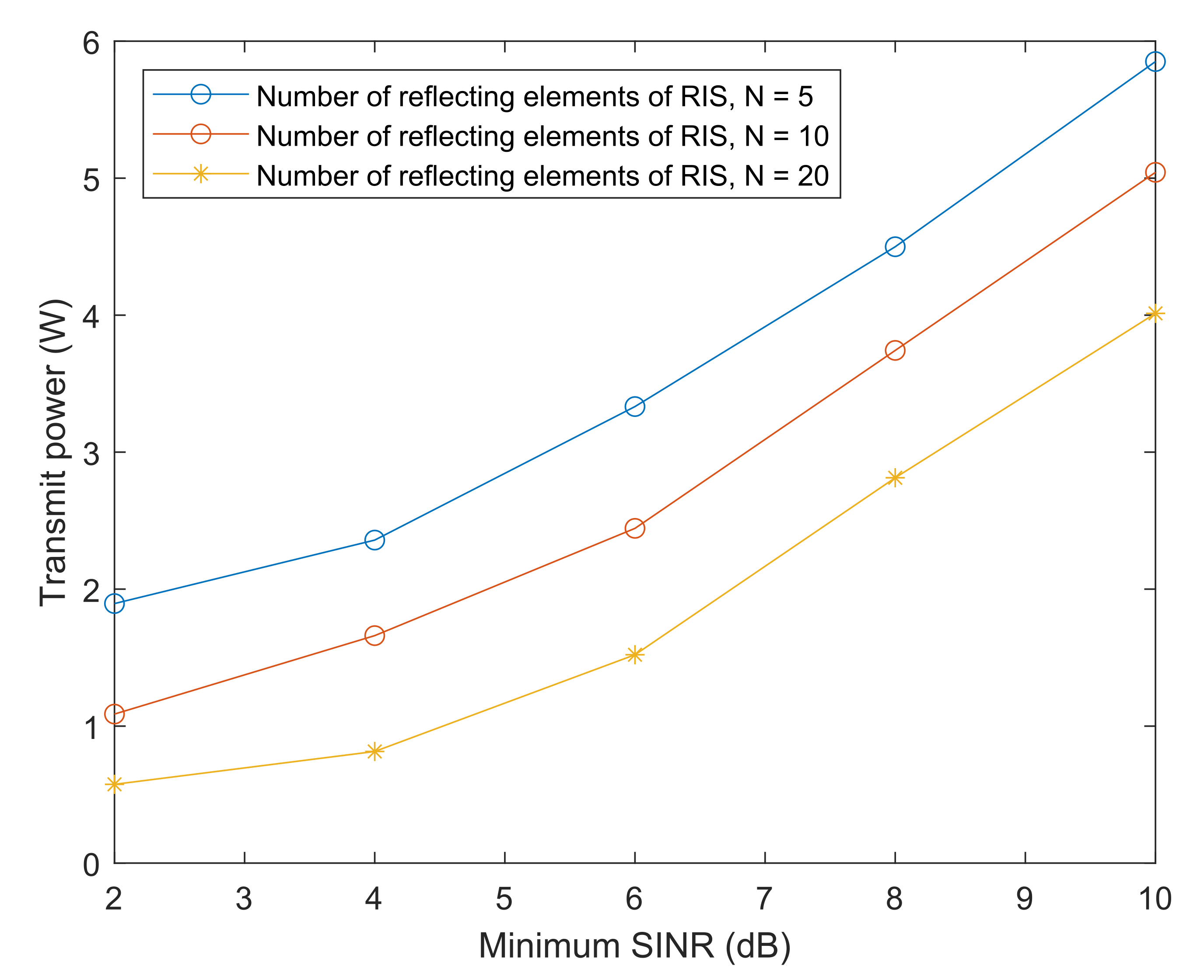
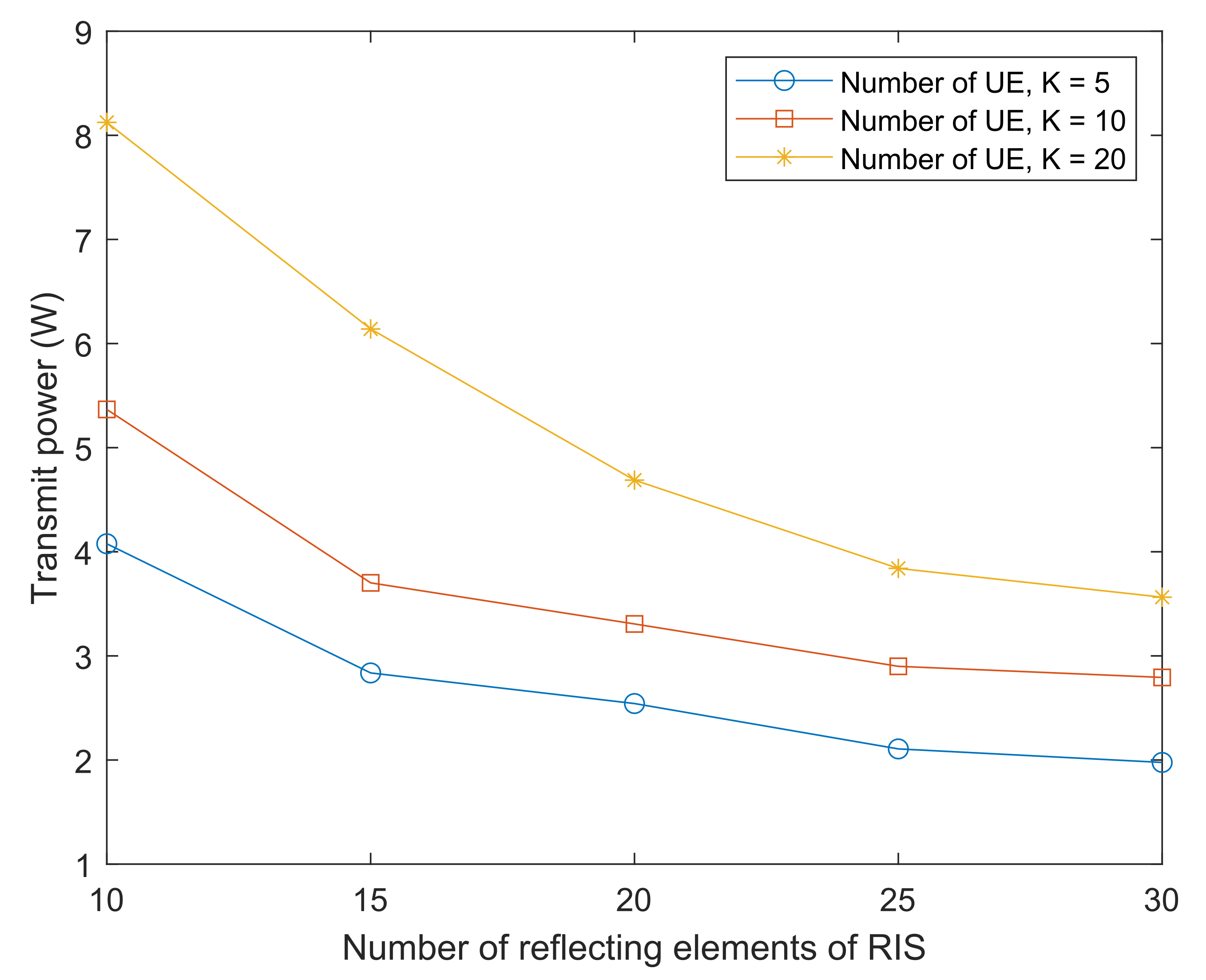
4. Simulation Results

The results of the algorithm simulation are presented in this section. In the setup of the simulation as presented in Figure 2, the system’s RIS lies at point (40,10) m and the base station is at point (0,0) m. The sensors are laid out within a circular area in a uniform and random way. The radius value is 5 m and the center of the circle is at point (70,0) m. Furthermore, all of the system’s channels are modeled as large-scale and small-scale fading channels. The channel’s large-scale fading model is represented as follows
PL = PL r e f 10 α lg d d r e f
where PL r e f represents the reference distance path loss( d r e f = 1 m) and α and d represent the path loss exponent and communication distance in meters, respectively. The small-scale fading is modeled by the Rayleigh distribution. All parameters used in the simulations are provided in Table 1. We used a computer with 11th-Gen Intel(R) Core(TM), i7-11800H @ 2.30GHz CPU, and 16.0 GB RAM to obtain the simulation results.
Figure 3 demonstrates the second algorithm’s convergence behavior. It is easy to see that Algorithm 2 converges rapidly within several iterations. The same figure illustrates that an increase in the number of RIS reflecting cells can decrease the required BS transmitting power, which demonstrates the efficacy of the RIS-aided non-linear SWIPT system.
Figure 4 shows the minimum BS transmitting power versus the sensor’s minimum SINR requirement. It can be observed that a higher minimum SINR leads to higher minimum transmitting power consumption of the BS. This is due to the fact that more power consumption is needed to compensate for the increase in the minimum SINR of the sensor. Furthermore, it can be seen that increasing the number of RIS reflecting cells can effectively decrease BS transmitting power consumption.
Figure 5 presents the BS transmitting power versus the number of RIS reflecting cells, showing that the BS transmitting power consumption decreases with an increased the number of RIS reflecting cells, especially for a system with a large number of sensors. Using K = 20 (the number of sensors) as an example, the BS transmitting power can be decreased by about 56% when increasing the number of RIS reflecting cells from 10 to 30, which demonstrates the effectiveness of integrating RIS into SWIPT with nonlinear energy harvesting.
The transmitting power as a function of the minimum harvested power with different numbers of RIS reflecting cells is demonstrated in Figure 6. It is easy to see that the total BS transmitting power consumption increases when the minimum harvested power requirements of the sensors becomes large. This is because more transmitting power is needed to compensate for the harvested power of the sensors. Moreover, from the same figure it can be seen that increasing the number of RIS reflecting cells can effectively decrease the required transmitting power consumption even when increasing the minimum harvested power.

5. Conclusions

In this paper, we investigate the problem of optimizing the total BS transmitting power consumption in an RIS-aided SWIPT sensor system. According to the investigated system model, the solution to the optimization problem needs to satisfy the minimum SINR and EH power requirements of each sensor, the PS ratio constraints, the and RIS unit modulus. It is difficult to solve this problem on account of its non-convex constraints and coupled variables. Using the BCD technique, however, it can be decoupled into two non-convex subproblems. Then, the SDR and SCA techniques can be introduced to transform the non-convex constraints to approximate subproblems in solvable form. We obtained the original problem’s optimal solution by iteratively optimizing the subproblems. Our numerical simulation results show that the required BS transmitting power can be effectively decreased by adding RIS to a SPWIT system, even when using a nonlinear harvest model.

Author Contributions

Funding acquisition, Y.Y.; Writing—original draft, H.Z.; Writing—review & editing, X.L. and C.H. All authors have read and agreed to the published version of the manuscript.

Funding

This work was funded by the Guangdong Basic Research Program under Grant 2019A1515110358.

Institutional Review Board Statement

Not applicable.

Informed Consent Statement

Not applicable.

Data Availability Statement

Not applicable.

Conflicts of Interest

The authors declare no conflict of interest.

References

  1. Li, X.; Zhang, C.; He, C.; Chen, G.; Chambers, J.A. Sum-Rate Maximization in IRS-Assisted Wireless Power Communication Networks. IEEE Internet Things J. 2021, 8, 14959–14970. [Google Scholar] [CrossRef]
  2. Pan, C.; Ren, H.; Wang, K.; Elkashlan, M.; Nallanathan, A.; Wang, J.; Hanzo, L. Intelligent reflecting surface aided MIMO broadcasting for simultaneous wireless information and power transfer. IEEE J. Sel. Areas Commun. 2020, 38, 1719–1734. [Google Scholar] [CrossRef]
  3. Bai, T.; Pan, C.; Deng, Y.; Elkashlan, M.; Nallanathan, A.; Hanzo, L. Latency minimization for intelligent reflecting surface aided mobile edge computing. IEEE J. Sel. Areas Commun. 2020, 38, 2666–2682. [Google Scholar] [CrossRef]
  4. Wu, Q.; Zhang, R. Joint Active and Passive Beamforming Optimization for Intelligent Reflecting Surface Assisted SWIPT under QoS Constraints. IEEE J. Sel. Areas Commun. 2020, 38, 1735–1748. [Google Scholar] [CrossRef]
  5. Deng, Z.; Pan, Y. Optimal Beamforming for IRS-Assisted SWIPT System with an Energy-Harvesting Eavesdropper. Electronics 2021, 10, 2536. [Google Scholar] [CrossRef]
  6. Yang, L.; Zeng, Y.; Zhang, R. Wireless Power Transfer with Hybrid Beamforming: How Many RF Chains Do We Need? IEEE Trans. Wirel. Commun. 2019, 17, 6972–6984. [Google Scholar] [CrossRef]
  7. Mahdi Elsiddig Haroun, F.; Mohamad Deros, S.N.; Ahmed Alkahtani, A.; Md Din, N. Towards Self-Powered WSN: The Design of Ultra-Low-Power Wireless Sensor Transmission Unit Based on Indoor Solar Energy Harvester. Electronics 2022, 11, 2077. [Google Scholar] [CrossRef]
  8. Albert, S. Wearable Circular Polarized Antennas for Health Care, 5G, Energy Harvesting, and IoT Systems. Electronics 2022, 11, 427. [Google Scholar]
  9. Chen, S.; Liu, D.; Zhao, Y. Target Localization and Power Allocation Using Wireless Energy Harvesting Sensors. Electronics 2021, 10, 2592. [Google Scholar] [CrossRef]
  10. Sarkar, N.I.; Singh, D.P.; Ahmed, M. A Survey on Energy Harvesting Wireless Networks: Channel Capacity, Scheduling, and Transmission Power Optimization. Electronics 2021, 10, 2342. [Google Scholar] [CrossRef]
  11. Ropokis, G.A.; Bithas, P.S. Wireless Powered Relay Networks: Rate Optimal and Power Consumption-Aware WPT/SWIPT. IEEE Trans.Veh. Technol. 2022, 71, 8574–8590. [Google Scholar] [CrossRef]
  12. Oleiwi, H.W.; Al-Raweshidy, H. Cooperative SWIPT THz-NOMA/6G Performance Analysis. Electronics 2022, 11, 873. [Google Scholar] [CrossRef]
  13. Wang, Z.S.; Lin, L.H.; Wen, J.H.; Lin, Y.J.; Weng, C.E. Performance Analysis of AF Cooperative Relaying Networks with SWIPT. Electronics 2022, 11, 589. [Google Scholar] [CrossRef]
  14. Selim, K.K.; Wu, S.; Saleeb, D.A.; Ghoneim, S.S. A Quad-Band RF Circuit for Enhancement of Energy Harvesting. Electronics 2021, 10, 1160. [Google Scholar] [CrossRef]
  15. Mansour, M.M.; Torigoe, S.; Yamamoto, S.; Kanaya, H. Compact and Simple High-Efficient Dual-Band RF-DC Rectifier for Wireless Electromagnetic Energy Harvesting. Electronics 2021, 10, 1764. [Google Scholar] [CrossRef]
  16. Sarker, M.R.; Saad, M.H.; Olazagoitia, J.L.; Vinolas, J. Review of Power Converter Impact of Electromagnetic Energy Harvesting Circuits and Devices for Autonomous Sensor Applications. Electronics 2021, 10, 1108. [Google Scholar] [CrossRef]
  17. Boshkovska, E.; Ng, D.W.K.; Zlatanov, N.; Schober, R. Practical Non-Linear Energy Harvesting Model and Resource Allocation for SWIPT Systems. IEEE Commun. Lett. 2015, 19, 2082–2085. [Google Scholar] [CrossRef]
  18. Mukherjee, P.; Lajnef, S.; Krikidis, I. MIMO SWIPT Systems with Power Amplifier Nonlinearities and Memory Effects. IEEE Wirel. Commun. Lett. 2020, 9, 2187–2191. [Google Scholar] [CrossRef]
  19. Ma, R.; Wu, H.; Ou, J.; Yang, S.; Gao, Y. Power Splitting-Based SWIPT Systems with Full-Duplex Jamming. IEEE Trans. Veh. Technol. 2020, 69, 9822–9836. [Google Scholar] [CrossRef]
  20. Ketcham, R.P.; Verdyck, J.; Moonen, M. Joint Beamforming and Power Allocation for Multiuser MISO Broadcast Channel SWIPT Employing OFDM. IEEE Access 2021, 9, 165154–165172. [Google Scholar] [CrossRef]
  21. Choi, K.W.; Hwang, S.I.; Aziz, A.A. Simultaneous Wireless Information and Power Transfer (SWIPT) for Internet of Things: Novel Receiver Design and Experimental Validation. IEEE Internet Things J. 2020, 7, 2996–3012. [Google Scholar] [CrossRef]
  22. Boshkovska, E.; Ng, D.W.K.; Zlatanov, N.; Koelpin, A.; Schober, R. Robust Resource Allocation for MIMO Wireless Powered Communication Networks Based on a Non-Linear EH Model. IEEE Trans Commun. 2017, 65, 1984–1999. [Google Scholar] [CrossRef]
  23. Wu, Q.; Tao, M.; Ng, D.W.K.; Chen, W.; Schober, R. Energy efficient resource allocation for wireless powered communication networks. IEEE Trans. Wirel. Commun. 2016, 15, 2312–2327. [Google Scholar] [CrossRef]
  24. Zhou, G.; Ren, C.P.H.; Wang, K.; Nallanathan, A. A framework of robust transmission design for IRS-aided MISO communications with imperfect cascaded channels. IEEE Trans. Signal Process. 2020, 68, 5092–5106. [Google Scholar] [CrossRef]
  25. Lu, Y.; Xiong, K.; Fan, P.; Ding, Z.; Zhong, Z.; Letaief, K.B. Secrecy Energy Efficiency in Multi-Antenna SWIPT Networks with Dual-Layer PS Receivers. IEEE Trans. Wirel. Commun. 2020, 196, 4290–4306. [Google Scholar] [CrossRef]
  26. Razaviyayn, M.; Hong, M.; Luo, Z.-Q. A unified convergence analysis of block successive minimization methods for nonsmooth optimization. SIAM J. Optim. 2013, 23, 1126–1153. [Google Scholar] [CrossRef] [Green Version]
Figure 1. RIS-aided multi-sensor wireless SWIPT model.
Electronics 11 02681 g001
Figure 2. The simulation setup of the proposed system.
Electronics 11 02681 g002
Figure 3. The convergence behaviour of the proposed algorithm.
Electronics 11 02681 g003
Figure 4. Transmitting power consumption versus sensor’s minimum SINR requirements.
Electronics 11 02681 g004
Figure 5. Transmitting power consumption versus the number of RIS reflecting elements.
Electronics 11 02681 g005
Figure 6. Transmitting power versus minimum harvested power.
Electronics 11 02681 g006
Table 1. Parameter setup.
ParameterValue
number of sensors K5
antenna number of BS M5
reflecting elements of RIS N[5, 20]
path loss P L r e f −30 dB
reference distance d r e f 1 m
path loss exponent α B S s e n s o r 4
path loss exponent α B S R I S 2.2
path loss exponent α R I S s e n s o r 2
minimum SINR requirement of the kth sensor γ k 10 dB
noise power σ k 2 , δ k 2 −174 dBm
nonlinear EH parameters a6400
nonlinear EH parameters b0.003
maximum harvested power e k −10 dB
Publisher’s Note: MDPI stays neutral with regard to jurisdictional claims in published maps and institutional affiliations.

