Article

Development of Electric Drive on the Basis of Five-Phase Synchronous Electric Motor

1
Department of Automation and Production Systems, Faculty of Mechanical Engineering, University of Zilina, 010 26 Zilina, Slovakia
2
Mechatronic Systems Department, Kalashnikov Izhevsk State Technical University, 7, Studencheskaya Str., 426069 Izhevsk, Russia
*
Author to whom correspondence should be addressed.
Electronics 2022, 11(17), 2680; https://doi.org/10.3390/electronics11172680
Submission received: 29 July 2022 / Revised: 20 August 2022 / Accepted: 25 August 2022 / Published: 26 August 2022
(This article belongs to the Section Systems & Control Engineering)

Abstract

:
This paper shows a model of a five-phase synchronous motor with permanent magnets and a simulation model of a control device. A simulation model in the SimInTech software product is built. The transient time is 0.03 s when a stepped input is applied. When the load moment of inertia increases by a factor of 10, the accuracy of speed response decreases. The maximum motor speed error is 40% at a time of 0.2 s. This is a consequence of changing the model of the control object. It is suggested to perform model identification and adapt PI controllers according to load parameters.

1. Introduction

Industrial use of electric drives began at the beginning of last century. At that time, direct voltage or alternating voltage on three phases was used. One of the founders of electric drives is considered to be Dane X. Erested, who in 1820 showed the possibility of interaction between a magnetic field and a conductor with a current. The Frenchman A. Ampere in the same year developed the theory and built a mathematical model of this interaction. British scientist M. Faraday in 1821 demonstrated the principle of transformation of electric energy into mechanical energy through the electromagnetic field. Russian scientists B.S. Jacobi and E.H. Lenzu in 1834 created the first direct current electric motor. In 1837 the American Davenport built an electric motor with a simpler commutator. In 1838 B.S. Jacobi improved the design of the electric motor, which is the prototype of the modern electric machine. In 1841, Englishman C. Whitson built a single-phase synchronous electric motor. In 1876, Russian scientist P.N. Yablochkov developed several designs of synchronous generators to power the candles he invented, and also invented a transformer. In 1888, Italian G. Ferraris and Yugoslavian N. Tesla discovered the phenomenon of rotating magnetic fields, which initiated the design of multiphase electric motors. Ferraris and Tesla developed several models of two-phase AC motors. The Russian electrical engineer M.O. Dolivo-Dobrovolsky developed a three-phase alternating current system in 1889. In the same year, he patented an asynchronous electric motor with a squirrel-cage rotor, and a few later with a phase rotor. M.O. Dolivo-Dobrovolsky also developed a 3-phase synchronous generator and 3-phase transformer, the designs of which remain virtually unchanged today.
Most AC motors were designed as three-phase devices. In theory, AC motors can be built with any number of phases. Drives with a large number of phases have a number of advantages compared with conventional three-phase drives: reduction in amplitude and increase in the frequency of moment ripple, reduction in harmonic rotor currents (if there is a rotor winding), reduction in the value of electric current per phase without increasing the voltage per phase, reduction in DC link current harmonics, higher reliability and increased power at the same mass [1].
Paper [2] investigates a kind of five-phase dual-rotor permanent-magnet synchronous motor (DRPMSM), which contains dual rotors and a single stator. This kind of motor has the potential advantages of high power density, high reliability and high efficiency, which make it more appropriate for use in electric vehicles (EVs). In order to evaluate the most suitable power level for this kind of structure, the electromagnetic, thermal and mechanical characteristics are investigated in this paper. The length-to-diameter ratio of motors is researched to obtain the highest power density and then the optimum ratio is obtained. Based on the optimum ratio, the thermal characteristics are researched under natural conditions and forced-air cooling conditions with different wind speeds. In addition, the mechanical characteristics are analyzed under no-load and different load conditions, respectively. All of the results are analyzed by two-dimension (2-D) and three-dimension (3-D) finite element method (FEM) simulation, which provides a good reference to select a suitable power level for this kind of motor structure [2].
The realization of a multiphase motor with more than three phases is possible even on the basis of a stator package of a three-phase machine with insignificant modernization of winding scheme. These factors allow us to consider electric traction on the basis of seven-phase machines as an alternative to the three-phase electric drive. Seven-phase motor (compared to three-phase), depending on the ratio of the number of turns in a phase, has a smaller nominal phase current, or a smaller phase voltage. When the number of phases is increased, a reduction in copper consumption is expected. The level of noise and vibrations of electromagnetic origin in a seven-phase motor is lower in comparison with a three-phase motor, which is a consequence of a number of features of the seven-phase winding. The subject of research is seven-phase motor winding (winding connection diagram—“star”), connected to a bridge converter, namely its ability to reduce vibrations of electromagnetic origin (in comparison with three-phase winding). The mode of pulsation of the common point potential of the seven-phase winding relative to the “zero” of the converter was investigated. The amplitude modulation of the space-time voltage vector of the seven-phase winding under the influence of pulsation of the common point potential relative to the “zero” of the converter was also investigated. During theoretical studies, the Fourier series decomposition method was used, as well as methods of vector analysis. To confirm the theoretical results, experimental studies of model samples of seven-phase and three-phase synchronous motors were carried out. The experiments were carried out on special equipment designed to study control algorithms of converters implementing space-time vector modulation of multiphase machines. The main result of the work is that a seven-phase motor (winding connection diagram—“star”) has a lower value of pulsations of the winding common point potential relative to the converter “zero” as compared to a three-phase motor. The numerical values of the ripple were determined and verified experimentally. This indicates that the level of ripples of electromagnetic origin is reduced when using a simple converter operation algorithm. The obtained results can be used in the creation of electric traction with vector control on the basis of seven-phase motors [3]. It should be noted that the seven-phase motor has more complex power electronics, the core of which are 14 transistors and more complex control algorithms with high computational complexity in vector control compared to a five-phase synchronous motor.
The subject of the study is a five-phase winding of an ABCDE motor with a spatial phase shift connected to a converter that forms a time phase shift of ACEBD. The process of forming the resulting voltage vector with one of the converter control algorithms is investigated, and the voltage ripple level of the common point of the five-phase winding relative to the converter zero is determined. When conducting theoretical studies used the method of decomposition in a Fourier series, as well as methods of vector analysis. To confirm the theoretical results, experimental studies of a prototype model of a five-phase synchronous motor were carried out. The main results are that with a time sequence of alternating ACEBD phases of a symmetrical five-phase winding, the “working” resulting voltage vector is the third harmonic vector, and its rotation frequency is three times the frequency of the converter. The practical significance of the work is that with a single frequency converter, the rotational speed of the resulting voltage vector of the five-phase winding has two values and can change discretely depending on the time sequence of the phase alternation. This property can be used to regulate the engine speed in a modern traction electric drive [4,5].
The most important characteristics of a modern drive are high reliability, good control characteristics, low maintenance and repair requirements, and low operating costs. New power semiconductor elements, such as MOSFETs and IGBTs, increase the control capabilities of electric machines [6]. In our study, a PWM frequency of 20 kHz is chosen, which will provide a good ratio of the quality of the generated signal to the power converter efficiency. FDS9945 transistors were used.
Studies in the field of modern electric drives are given in works [7,8,9,10,11,12,13,14,15,16].
Article [7] reviews the recent advancements of multiphase machines in several aspects such as topology, control, and performance to evaluate the possibility of exploiting them more in electric vehicle (EV) applications in the future.
In papers [8,9,10,11], an optimally-tuned PID control. The parametric synthesis of the PID controller on the basis of continuous and discrete models was performed. Numerical simulations using SimInTech for the adaptive regulator taking into account the cargo weight (from empty to maximum loaded) were carried out. The scheme of automatic selection of actuator PID coefficients considering the cargo weight was proposed. As a result of the parametric synthesis of discrete PID control law, optimum values of its amplification coefficients were determined. In [12], the authors discussed the stability analysis and calculation of oscillatory processes based on a dynamic model, the parametric identification of which was performed on the basis of experimental data and the results of a multidimensional numerical simulation. In our work, we used two PI regulators. The internal fast-acting PI regulator is by electric current in the rotating coordinate system. The external PI regulator is by angular velocity.
In the paper [13], the results of research and model tests of asynchronous induction machines of modular design are presented. Several positive aspects of the practical realization of this design and the characteristic features of its mathematical description in comparison with the synchronous reactive machine of modular design are pointed out. An algorithm for the calculation of the machine parameters is considered and a computer model of the electric drive in the MATLAB-Simulink package is developed.
In [14], the authors have established and solved the problem of the analytical design law of direct adaptive control of the electric actuator. It is shown that the proposed law can be implemented on an analog or computer PID controller platform. In this case, a traditional PID controller can be transformed into an adaptive one by simply changing its setting parameters while keeping the composition of the elements unchanged, which include the integrator, differentiator, and amplifiers.
Article [15,16] discusses the development of advanced electric drive control systems and explores the challenges of modeling real physical objects, including control system design, testing, and the development of working prototypes. An algorithm for executable code development was presented.
The papers [17,18,19,20,21] scientifically discuss the progressive diagnostics of electrical drives with sensor support and the proposed AI (artificial intelligence) model.
This paper builds a model of a five-phase synchronous motor controlled by a transistor voltage converter-regulator based on power semiconductor switches. A prototype motor was made and tested. The influence of motor operating modes and load moment of inertia on the accuracy of the motor speed is investigated.

2. Materials and Methods

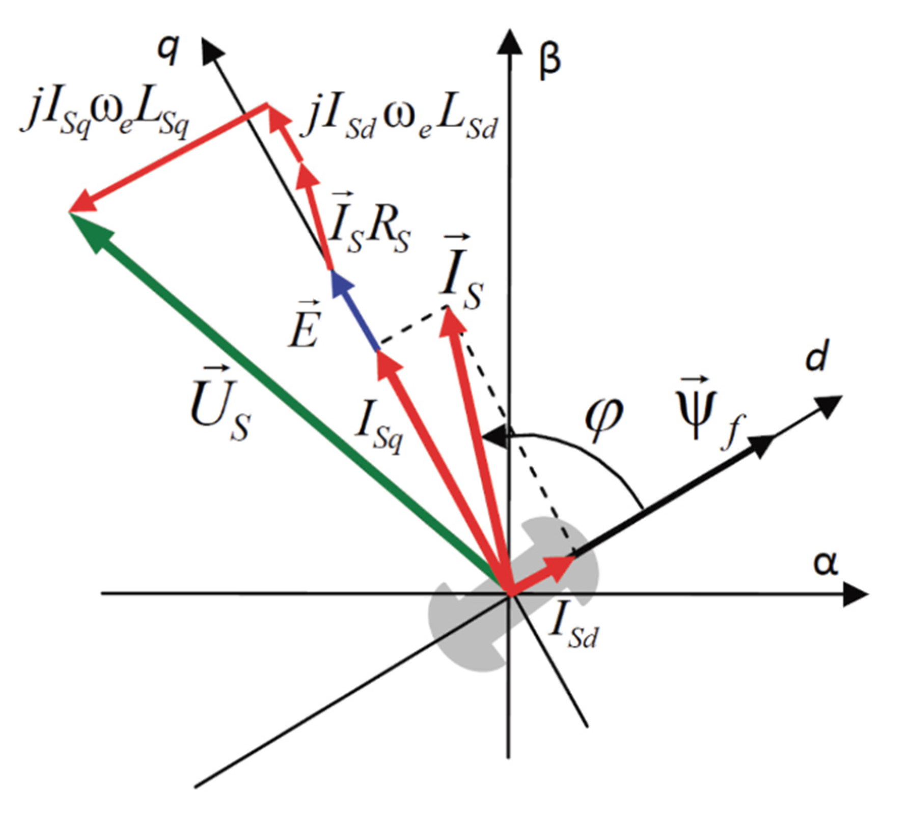
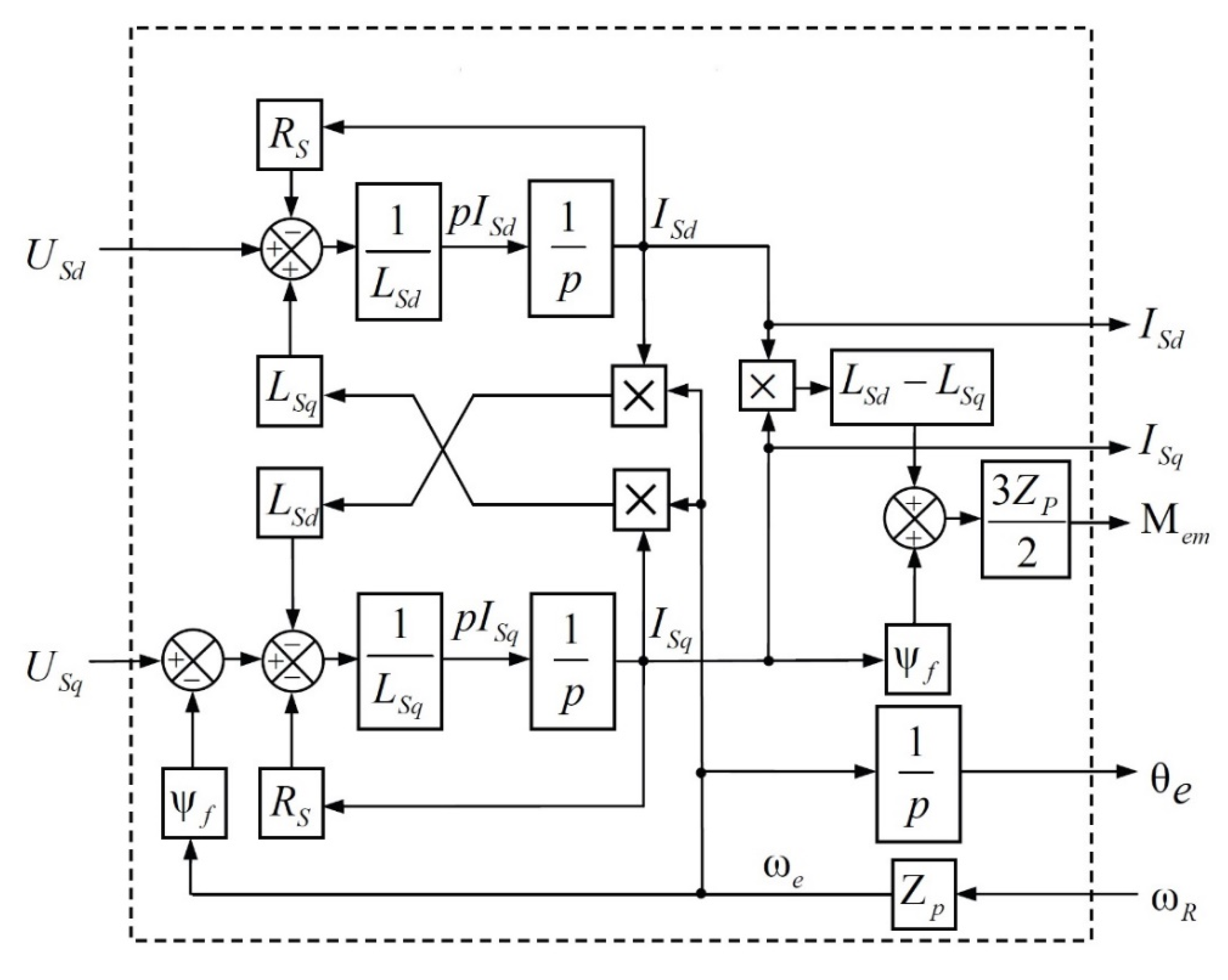
2.1. Mathematical Model of a Five-Phase Synchronous Motor

Figure 1 shows a vector diagram explaining the processes occurring in a synchronous motor. We will consider them in a rotating coordinate system dq, the axis d of which is oriented along the rotor flux [22].
The rotor of the motor, being a permanent magnet, produces a flux capacitance ψf, equal to the product of the rotor flux by the number of turns of the stator winding. The vector of this current-circuiting is directed along the rotor axis d from the positive pole to the negative pole and lags behind the stator current vector Is by some angle φ. The constant flux of the rotating rotor creates in stator windings the vector of electromagnetic field (EMF) E directed at a right angle to the flux and leading it by 90 degrees (the derivative of rotor current-current f/dt) [22].
The amplitude of the EMF vector is determined by the expression:
E = ψfωe,
where ωe is the rotational speed of the field; ωe = Zp ωR; ωR is the rotor speed; Zp is the number of motor pole pairs.
According to Figure 1, we can write the following vector relation [9]:
US = E + ISRS + jωe (ISdLSd + ISqLSq),
where US is the stator voltage vector; Is is the stator current vector; ISd and ISq are its components; LSd and LSq are stator inductance along d and q axes; RS is stator resistance.
According to Figure 1, the stator voltage vector is balanced by the EMF vector and voltage drop on active (RS) and reactive (LSd and LSq) resistances of the stator winding.
Motor torque arises as a result of force interaction between current and stator current-current vectors. The torque is determined by the vector product of the effective values of these vectors. Taking into account the phase and the number of pole pairs of the motor (Zp), the following expression for calculating the motor torque can be written [9]:
M e m = 3 2 Z p ( I S × ψ S ) = 3 2 Z p | I S | | ψ S | sin φ
where φ is the angle between the current and stator current-current vectors.
The formula for calculating the electromagnetic torque of the motor in the dq coordinate system will look like this [8]:
M e m = 3 2 Z p ( I S q ψ f + I S d I S q ( L S d L S q ) )
The motor stator is a five-phase inductor coil and assuming that magnetic losses are neglected, the following expression can be written for it in the dq coordinate system, rotating with the field.
U S d = L S d d I S d d t + R S I S d ω e L S q I S q U S q = L S q d I S q d t + E + R S I S q + ω e L S d I S d ,
Let us write Equation (5) in Cauchy form and add the equation of electromagnetic torque.
d I S d d t = 1 L S d ( U S d R S I S d + ω e L S q I S q ) d I S q d t = 1 L S q ( U S q R S I S q ω e L S d I S d ψ f ω e ) M e m = 3 2 Z p ( I S q ψ f + I S d I S q ( L S d L S q ) ) ,
By Equation (6) we can build a model of electromagnetic processes of the synchronous motor, as shown in Figure 2.
The model is augmented with a rotor field angle calculator (θe), which is obtained by integrating the field velocity (ωe). The input signals of the model are voltages and velocity, and the output signals are currents, electromagnetic moment and field angle.
The rotor speed of the motor in this case is determined by the expression:
ω R = 1 J ( M e m M L ) d t
where: J is the moment of inertia applied to the rotor; ML is the load torque applied to the rotor.
Accordingly, the output of the electromagnetic moment of the motor model should be fed to the model of the mechanical system, made on the elements of the “Mechanics” library, which allows us to simulate complex transfer mechanisms and loads. The mechanical system model converts the torque signal into speed, which in turn is fed to the corresponding input of the motor model.
The motor receives a five-phase voltage generated by pulse width modulation, has a load resistance torque with some moment of inertia, and outputs electromagnetic torque and speed. The mathematical model of a five-phase motor is used to simulate a five-phase synchronous machine.

2.2. Synchronous Motor Drive System Based on Five-Phase Voltage Regulator Using IGBT
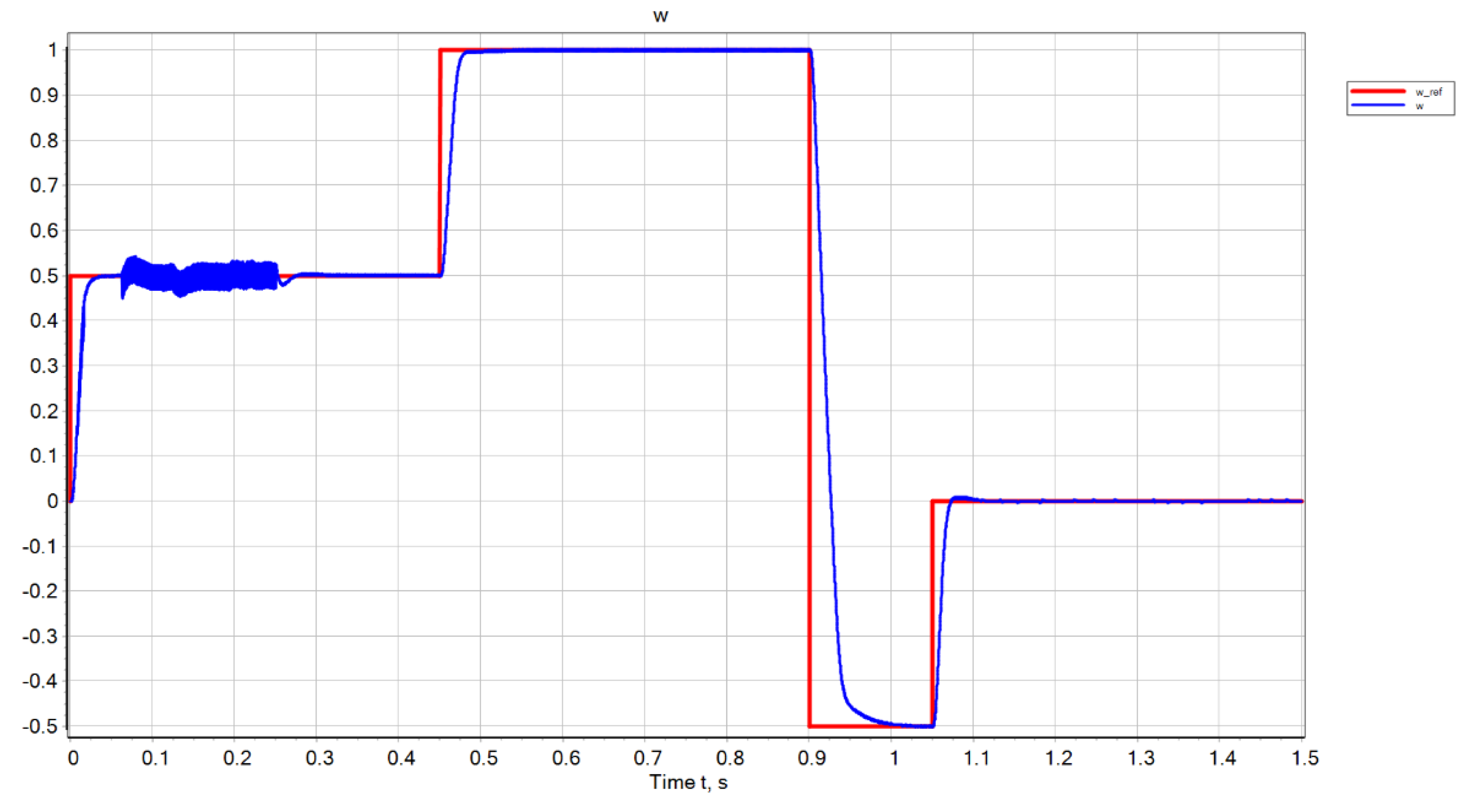
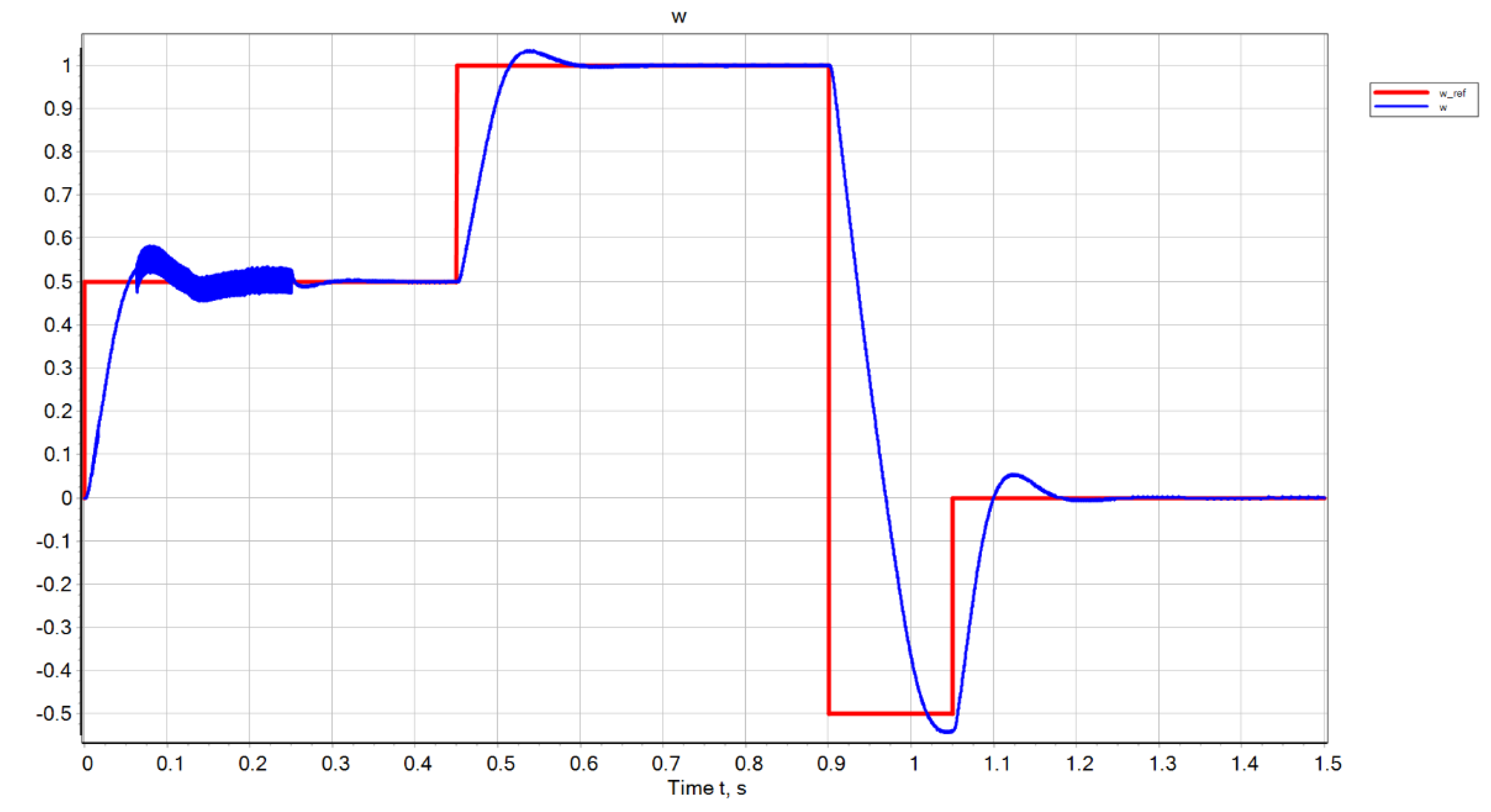
The simulation model of the motor and control device is developed based on the PI controller of angular speed using position sensors, electric current sensors and IGBT transistors as power switches. The simulation model of the control device in the SimInTech software product is shown in Figure 3. The speed is given in relative units relative to the rated motor speed. The speed equal to 1 corresponds to the nominal speed of the motor. The control unit has two feedback loops. The external feedback loop is implemented as a PI motor speed controller. The internal fast feedback loop is implemented as two PI controllers of the motor electric current projections on the d and q axes.
The motor parameters are given in Table 1. The parameters of the PI controller of motor speed are given in Table 2. Parameters of the PI controller of projections of electric motor current on the d and q axes are given in Table 3.

3. Results

Figure 4 shows the given angular speed and angular speed of the motor for a rectangular voltage input signal with a load moment of inertia of 0.7 kg∙m2.
When a stepped action is applied to the input, the transient time is 0.03 s. at a load moment of inertia of 0.7 kg∙m2.
Figure 5 shows the reference angular speed and angular speed of the motor for a rectangular voltage input signal with a load moment of inertia of 2.1 kg∙m2.
When a stepped action is applied to the input, the transient time is 0.1 s. at a load moment of inertia of 2.1 kg∙m2.
If the motor is accelerated smoothly, the accuracy of the trajectory increases, as shown in Figure 6.
The smaller error of the angular velocity with its linear change is explained by the fact that the motor rotor together with the load has a certain moment of inertia. The sum of moments (electromagnetic torque with sign ‘+’, load torque with sign ‘–’) is equal to the product of the moment of inertia by the angular acceleration. With a stepped input signal specifying angular velocity, the angular acceleration tends to infinity at the time of the jump, with a linear change in angular velocity, the angular acceleration will be a constant. To provide infinite angular acceleration requires infinite motor torque and therefore infinite electric current. The finite value of the electric current of real devices determines the angular velocity error is smaller when it changes linearly than when the input signal is stepped.
Figure 6 shows the given angular velocity and angular velocity of the motor when applied to the input with a load moment of inertia of 0.7 kg∙m2. Figure 7 shows the given angular velocity and angular velocity of the motor when applied to the input with a load moment of inertia of 2.1 kg∙m2.
If the load moment of inertia increases by a factor of 10, the speed accuracy decreases. The maximum motor speed error is 40% at a time of 0.2 s. This is a consequence of changing the model of the control object. Therefore, it is necessary to perform model identification and adapt PI controllers. When the load moment of inertia threshold value corresponding to the motor torque parameters is exceeded, an alarm signal must be issued.
To study the principles of control and the development of power boards, a mockup of the motor was developed (Figure 8). To study the control principles and the development of power boards, a mock-up engine was created (Figure 8). The mock-up of the engine has been created with CA support to enable the use of CAD, CAM, DFM, and other systems that help achieve higher product accuracies and help companies develop new products [23,24,25].
The stator is assembled from individual coils in 5 groups, each group is connected to one of the power supply phases, the phases are connected in a “star” pattern (Figure 9).
The rotor is two discs rigidly mounted on the shaft with permanent magnets inside (Figure 10 and Figure 11).
The housing of the layout is made according to the Nema 23 standard, which allows you to test the operation of the device on all systems that have the appropriate attachment (Figure 12).
The AS5600 magnetic encoder is used to control the rotor angle of rotation (Figure 13).
The prototype is fully assembled and functional (Figure 14).

4. Discussion

This paper considers five-phase synchronous motors and their advantages. The mathematical model of a five-phase motor in a rotating dq coordinate system is used to simulate. A simulation model of the control device is implemented in the SimInTech program. The five-phase motor control unit is based on two PI controller loops. The external control circuit is implemented as a PI controller for angular velocity. The internal control circuit is implemented as a PI controller for electric current. The results of the simulation of a five-phase motor with a stepped input signal and with a linear change in angular velocity are shown. As a result of the simulation, the transient times have been established. It is shown that with a linear change in angular velocity, the angular velocity error is smaller than with a step input signal. When the moment of inertia increases by a factor of three, the angular velocity overshoots and the angular velocity error increases. Five-phase synchronous motors with permanent magnets have been developed. Currently, most inverters for AC motors are three-phase. The wide implementation of five-phase motors requires the production of five-phase inverters based on 10 power MOSFET transistors. Further direction of research is related to the development of fault-tolerant control of five-phase motors. This requires the development of a diagnostic system that detects the fault associated with the loss of phase five-phase motor or its short circuit, or fault of power MOSFET transistors. Then the five-phase motor is controlled for 4 phases only, excluding the defective phase or MOSFET transistor.

5. Conclusions

In this paper, a simulation model of five-phase synchronous motors was developed in SimInTech software and the results were evaluated. The five-phase motor control device is implemented on the basis of two PI controller loops. The external control circuit is implemented as a PI controller of angular velocity. The internal control circuit is implemented as a PI regulator of electric current. The results of the simulation of a five-phase motor with a stepped input signal and with a linear change in angular velocity are shown. The transient time is 0.03 s when the step influence is applied to the input. The accuracy of speed response decreases when the load moment of inertia increases by a factor of 10. The maximum error in the motor speed is 40% at a time of 0.2 s. This is a consequence of changing the model of the control object. It is suggested to perform model identification and adapt PI controllers according to load parameters. A design of five-phase synchronous motors with permanent magnets has been developed. The five-phase synchronous motor has the following characteristics:
-
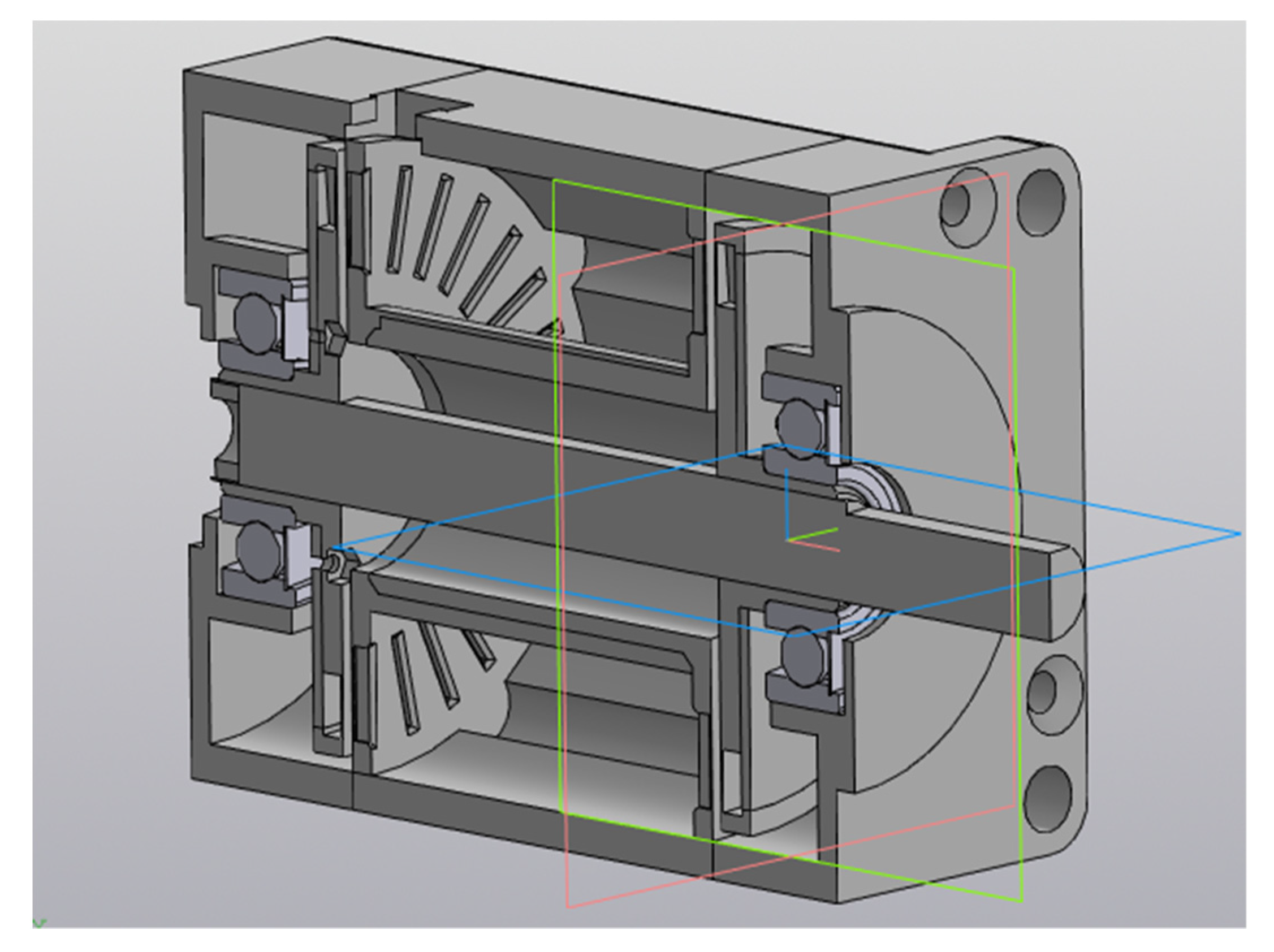
weight of the motor: 0.52 kg;
-
overall dimensions: 61 × 56 × 56 mm3;
-
nominal power: 55 Watts;
-
efficiency: 93%;
-
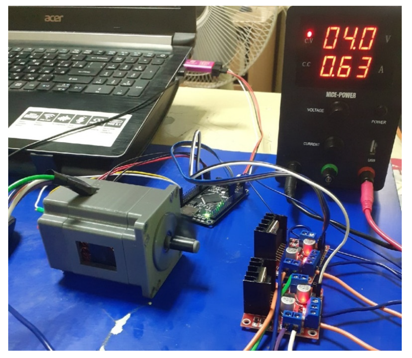
power supply voltage: 24 V;
-
rated current: 2.5 A;
-
nominal torque: 0.18 N∙m;
-
rated speed of rotation: 2960 rpm;
-
inertia moment of the rotor: 321∙10−7 kg∙m2.
-
All obtained parameters of the motor correspond to the technical specification.

Author Contributions

Conceptualization, Y.N. and A.B.; methodology, Y.N. and A.B.; writing—original draft preparation, Y.N.; writing—review and editing, V.T. and M.S.; supervision, I.K. and M.S.; project administration, V.T.; funding acquisition, I.K. and V.T. All authors have read and agreed to the published version of the manuscript.

Funding

This research was funded by the Ministry of Education, Science, research and Sport of the Slovak Republic under the project STIMULYMATADOR 1247/2018. Project title: Research and development of modular reconfigurable production systems using Smart Industry principles for automotive with pilot application in MoBearing Line industry.

Data Availability Statement

The data presented in this study are available on request from the corresponding author.

Conflicts of Interest

The authors declare no conflict of interest.

References

  1. Kumar, R.R.; Kumari, A.; Devi, P.; Chetri, C.; Kumar, K. Performance Characteristic Analysis of a Novel Dual Stator Carbon Fiber Frame Rotor Five-Phase Permanent Magnet Synchronous Motor for Electric Vehicles Application. In Proceedings of the 2020 IEEE International Conference on Power Electronics, Drives and Energy Systems (PEDES), Jaipur, India, 16–19 December 2020. [Google Scholar] [CrossRef]
  2. Zhao, J.; Liu, W.; Li, B.; Liu, X.; Gao, C.; Gu, Z. Investigation of Electromagnetic, Thermal and Mechanical Characteristics of a Five-Phase Dual-Rotor Permanent-Magnet Synchronous Motor. Energies 2015, 8, 9688–9718. [Google Scholar] [CrossRef]
  3. Tereshkin, V.M.; Grishin, D.A.; Tereshkin, V.V.; Balgazin, I.I. Seven-Phase Motor as an Alternative to Three-Phase Motor in Modern Electric Traction. New Russ. Electr. Power Ind. 2021, 1, 46–56. [Google Scholar]
  4. Tereshkin, V.M.; Aitov, I.L.; Grishin, D.A.; Tereshkin, V.V. Formation of the Resulting Vector of the Voltage of the Five-Phase Abcde Winding at the Temporary Sequence of Alternating the ACEBD Phases. 2019. Available online: https://elibrary.ru/download/elibrary_42305758_92805001.pdf (accessed on 28 July 2022).
  5. Virgala, I.; Frankovský, P.; Kenderová, M. Friction Effect Analysis of a DC Motor. Am. J. Mech. Eng. 2013, 1, 1–5. [Google Scholar] [CrossRef]
  6. Veszpremi, K.; Hunyar, M. New Application Fields of the PWM IGBT AC Chopper. In Proceedings of the 8th International Conference on Power Electronics and Variable Speed Drives, London, UK, 18–19 September 2000; pp. 46–51. [Google Scholar] [CrossRef]
  7. Salem, A.; Narimani, M. A Review on Multiphase Drives for Automotive Traction Applications. IEEE Trans. Transp. Electrif. 2019, 5, 1329–1348. [Google Scholar] [CrossRef]
  8. Božek, P.; Nikitin, Y. The Development of an Optimally-Tuned Pid Control for the Actuator of a Transport Robot. Actuators 2021, 10, 195. [Google Scholar] [CrossRef]
  9. Nikitin, Y. BLDC Motor Identification Based on Optimal Control Model in the State Space. IOP Conf. Ser. Mater. Sci. Eng. 2020, 971, 042063. [Google Scholar] [CrossRef]
  10. Bocko, J.; Delyová, I.; Frankovský, P.; Neumann, V. Lifetime Assessment of the Technological Equipment for a Robotic Workplace. Int. J. Appl. Mech. 2020, 12, 20500970. [Google Scholar] [CrossRef]
  11. Božek, P. Parametrical Synthesis of PID-Law Control Based on Continuous Model of Electric Cart Drive Based on Asynchronous Motor. Mechatron. Prod. Technol. Digit. Enterp. Latest Achiev. Chall. Trends. 2021, 1, 12–22. [Google Scholar]
  12. Lekomtsev, P.V.; Nikitin, Y.R.; Trefilov, S.A. DC Motor Identification Based on Quasi-Optimal Nonlinear Control Algorithm. Bull. IzhGTU Named M.T. Kalashnik 2021, 24, 68. [Google Scholar] [CrossRef]
  13. German-Galkin, S.G.; Lebedev, V.V.; Bormotov, A.V. Modular Synchronous Inductor Machine in the Electric Drive System. Mekhatronika Avtom. Upr. 2015, 16, 731–737. [Google Scholar] [CrossRef]
  14. Krasnodubets, L.A.; Oleynikov, A.M. PID Controller as a Platform for Implementation of the Adaptive Laws of the Electric Drive Control. Mekhatronika Avtom. Upr. 2016, 17, 809–816. [Google Scholar] [CrossRef]
  15. German-Galkin, S.G.; Gavrilov, R.S.; Mustafayev, Y.N. Structural and Simulation Models in the Model-Oriented Designing of the Electric Valve Actuator for a Rotary Support Device. Mekhatronika Avtom. Upr. 2017, 18, 56–63. [Google Scholar] [CrossRef]
  16. Liptak, T.; Virgala, I.; Frankovsky, P.; Sarga, P.; Gmiterko, A.; Balockova, L. A Geometric Approach to Modeling of Four- and Five-Link Planar Snake-like Robot. Int. J. Adv. Robot. Syst. 2016, 13, 1729881416663714. [Google Scholar] [CrossRef]
  17. Abramov, I.V.; Abramov, A.I.; Nikitin, Y.R.; Sosnovich, E.; Bozek, P.; Stollmann, V. Diagnostics of Electrical Drives. In Proceedings of the 2015 International Conference on Electrical Drives and Power Electronics (EDPE), Tatranska Lomnica, Slovakia, 21–23 September 2015; pp. 364–367. [Google Scholar]
  18. Peterka, J.; Nikitin, Y.R.; Božek, P. Diagnostics of Automated Technological Devices. MM Sci. J. 2020, 2020, 4027–4034. [Google Scholar] [CrossRef]
  19. Cisar, M.; Kuric, I.; Cubonova, N.; Zajacko, I.; Dodok, T.; Rudawska, A. Utilization of Educational Machine Tool for Training of Technical Diagnostics Based on Positioning Performance. In Proceedings of the XXII Slovak-Polish Scientific Conference on Machine Modelling And Simulations 2017 (MMS 2017), Sklené Teplice, Slovakia, 5–8 September 2017; Vasko, M., Handrik, M., Jakubovicova, L., Kopas, P., Blatnicka, M., Baniari, V., Stalmach, O., Sapietova, A., Saga, M., Eds.; University of Žilina, EDIS-Editing Centre of University of Žilina: Žilina, Slovakia, 2018; Volume 157. [Google Scholar]
  20. Nikitin, Y.; Božek, P.; Peterka, J. Logical–Linguistic Model of Diagnostics of Electric Drives with Sensors Support. Sensors 2020, 20, 4429. [Google Scholar] [CrossRef] [PubMed]
  21. Kuric, I.; Klackova, I.; Domnina, K.; Stenchlak, V.; Saga Jr, M. Implementation of Predictive Models in Industrial Machines with Proposed Automatic Adaptation Algorithm. Appl. Sci. 2022, 12, 1853. [Google Scholar] [CrossRef]
  22. Kalachev, Y.N. Modeling in Electric Drive; SimInTech: Moscow, Russia, 2019. [Google Scholar]
  23. Jakubowski, J.; Peterka, J. Design for Manufacturability in Virtual Environment Using Knowledge Engineering. Manag. Prod. Eng. Rev. 2014, 5, 3–10. [Google Scholar] [CrossRef]
  24. Peterka, J.; Pokorný, P. Influence of the Lead Angle from the Vertical Axis Milling on Effective Radius of the Cutter. Key Eng. Mater. 2014, 581, 44–49. [Google Scholar] [CrossRef]
  25. Beňo, M.; Zvončan, M.; Kováč, M.; Peterka, J. Circular Interpolation and Positioning Accuracy Deviation Measurement on Five Axis Machine Tools with Different Structures. Teh. Vjesn. Tech. Gaz 2013, 20, 479–484. [Google Scholar]
Figure 1. Vector diagram, which explains the processes occurring in a synchronous motor [20].
Electronics 11 02680 g001
Figure 2. Model of electromagnetic processes of the synchronous motor [14].
Electronics 11 02680 g002
Figure 3. Simulation model of the control device.
Electronics 11 02680 g003
Figure 4. Set angular velocity and angular velocity of the motor at a load moment of inertia of 0.7 kg∙m2.
Electronics 11 02680 g004
Figure 5. Set angular velocity and angular velocity of the motor at a load moment of inertia of 2.1 kg∙m2.
Electronics 11 02680 g005
Figure 6. Set angular velocity and angular velocity of the motor at a load moment of inertia of 0.7 kg∙m2.
Electronics 11 02680 g006
Figure 7. The specified angular velocity and angular velocity of the motor at a moment of inertia of the load 2.1 kg∙m2.
Electronics 11 02680 g007
Figure 8. Mockup of the motor.
Electronics 11 02680 g008
Figure 9. The stator of motor.
Electronics 11 02680 g009
Figure 10. The stator of motor.
Electronics 11 02680 g010
Figure 11. The rotor model of motor.
Electronics 11 02680 g011
Figure 12. The housing of the layout.
Electronics 11 02680 g012
Figure 13. Placing of the AS5600 magnetic encoder.
Electronics 11 02680 g013
Figure 14. The prototype of motor.
Electronics 11 02680 g014
Table 1. Motor parameters.
Parameter NameParameter DesignationParameter Value
Number of motor pole pairsZp42
Stator phase resistance, OhmRS16
Stator phase inductance, HnLS0.112
Rotor current coefficient, VbF0.4
Table 2. Parameters of PI motor speed controller.
Parameter NameParameter DesignationParameter Value
Proportional coefficientkp4
Integral coefficientki150
Table 3. Parameters of PI controller of projections of electric motor current on the d and q axes.
Parameter NameParameter DesignationParameter Value
Proportional coefficientkp4
Integral coefficientki400
Publisher’s Note: MDPI stays neutral with regard to jurisdictional claims in published maps and institutional affiliations.

