


0.4-V, 81.3-nA Bulk-Driven Single-Stage CMOS OTA with Enhanced Transconductance


Abstract
:1. Introduction
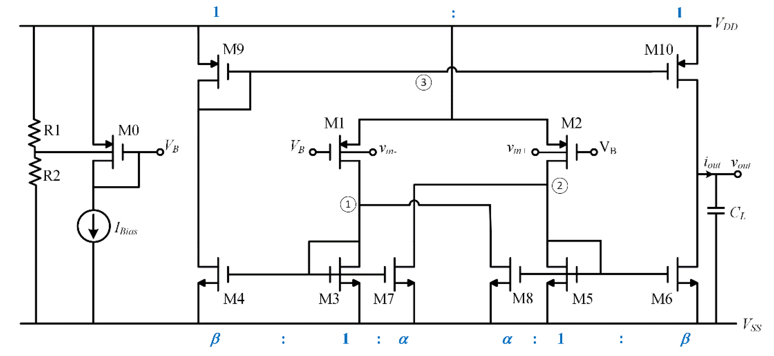
2. The Proposed Amplifier
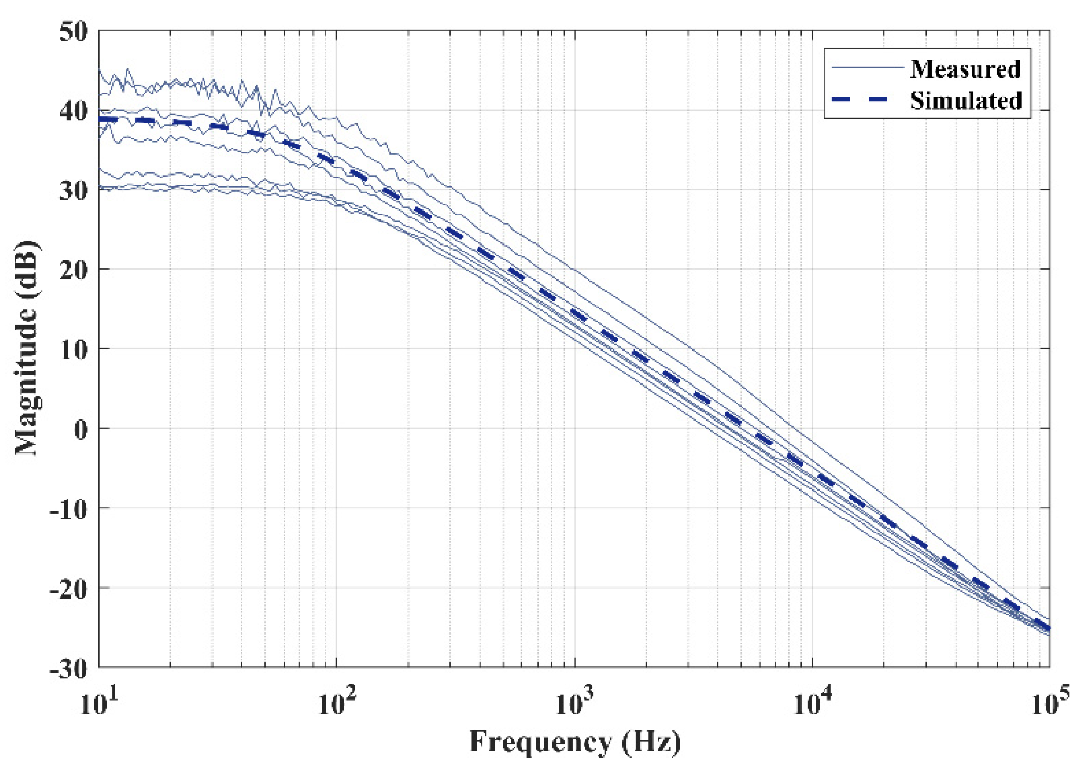
3. Results and Comparison
4. Conclusions
Author Contributions
Funding
Conflicts of Interest
References
- Richelli, A.; Colalongo, L.; Kovacs-Vajna, Z.; Calvetti, G.; Ferrari, D.; Finanzini, M.; Pinetti, S.; Prevosti, E.; Savoldelli, J.; Scarlassara, S. A Survey of Low Voltage and Low Power Amplifier Topologies. J. Low Power Electron. Appl. 2018, 8, 22. [Google Scholar] [CrossRef]
- Grasso, A.D.; Pennisi, S. Ultra-Low Power Amplifiers for IoT Nodes. In Proceedings of the 2018 25th IEEE International Conference on Electronics, Circuits and Systems (ICECS), Bordeaux, France, 9–12 December 2018; pp. 497–500. [Google Scholar]
- Enabling the Internet of Things: From Integrated Circuits to Integrated Systems; Alioto, M. (Ed.) Springer International Publishing: Cham, Switzerland, 2017; ISBN 978-3-319-51480-2. [Google Scholar]
- Sansen, W. 1.3 Analog CMOS from 5 Micrometer to 5 Nanometer. In Proceedings of the 2015 IEEE International Solid-State Circuits Conference—(ISSCC) Digest of Technical Papers, San Francisco, CA, USA, 22–26 February 2015; pp. 1–6. [Google Scholar]
- Baschirotto, A.; Chironi, V.; Cocciolo, G.; D’Amico, S.; De Matteis, M.; Delizia, P. Low Power Analog Design in Scaled Technologies. Proc. Top. Workshop Electron. Part. Phys. 2009, 103–110. [Google Scholar]
- Calhoun, B.H.; Daly, D.C.; Verma, N.; Finchelstein, D.F.; Wentzloff, D.D.; Wang, A.; Cho, S.; Chandrakasan, A.P. Design Considerations for Ultra-Low Energy Wireless Microsensor Nodes. IEEE Trans. Comput. 2005, 54, 727–740. [Google Scholar] [CrossRef]
- Blalock, B.J.; Allen, P.E.; Rincon-Mora, G. Designing 1-V Op Amps Using Standard Digital CMOS Technology. IEEE Trans. Circuits Syst. II Analog. Digit. Signal Process. 1998, 45, 769–780. [Google Scholar] [CrossRef]
- Grasso, A.D.; Monsurrò, P.; Pennisi, S.; Scotti, G.; Trifiletti, A. Analysis and Implementation of a Minimum-Supply Body-Biased CMOS Differential Amplifier Cell. Very Large Scale Integr. Syst. IEEE Trans. 2009, 17, 172–180. [Google Scholar] [CrossRef]
- Monsurró, P.; Pennisi, S.; Scotti, G.; Trifiletti, A. Exploiting the Body of MOS Devices for High Performance Analog Design. IEEE Circuits Syst. Mag. 2011, 11, 8–23. [Google Scholar] [CrossRef]
- Raikos, G.; Vlassis, S. Low-Voltage Bulk-Driven Input Stage with Improved Transconductance. Int. J. Circuit Theory Appl. 2011, 39, 327–339. [Google Scholar] [CrossRef]
- Cabrera-Bernal, E.; Pennisi, S.; Grasso, A.D.; Torralba, A.; Carvajal, R.G. 0.7-V Three-Stage Class-AB CMOS Operational Transconductance Amplifier. IEEE Trans. Circuits Syst. I Regul. Pap. 2016, 63, 1807–1815. [Google Scholar] [CrossRef]
- Carrillo, J.M.; Torelli, G.; Perez-Aloe Valverde, R.; Duque-Carrillo, J.F. 1-V Rail-to-Rail CMOS OpAmp with Improved Bulk-Driven Input Stage. IEEE J. Solid-State Circuits 2007, 42, 508–517. [Google Scholar] [CrossRef]
- Zuo, L.; Islam, S.K. Low-Voltage Bulk-Driven Operational Amplifier with Improved Transconductance. IEEE Trans. Circuits Syst. I Regul. Pap. 2013, 60, 2084–2091. [Google Scholar] [CrossRef]
- Sanchotene Silva, R.; Rodovalho, L.H.; Aiello, O.; Ramos Rodrigues, C. A 1.9 NW, Sub-1 V, 542 PA/V Linear Bulk-Driven OTA with 154 DB CMRR for Bio-Sensing Applications. J. Low Power Electron. Appl. 2021, 11, 40. [Google Scholar] [CrossRef]
- Vittoz, E.; Fellrath, J. CMOS Analog Integrated Circuits Based on Weak Inversion Operations. IEEE J. Solid-State Circuits 1977, 12, 224–231. [Google Scholar] [CrossRef]
- Stockstad, T.; Yoshizawa, H. A 0.9-V 0.5-Um Rail-to-Rail CMOS Operational Amplifier. IEEE J. Solid-State Circuits 2002, 37, 286–292. [Google Scholar] [CrossRef]
- Harrison, R.R.; Charles, C. A Low-Power Low-Noise CMOS Amplifier for Neural Recording Applications. IEEE J. Solid-State Circuits 2003, 38, 958–965. [Google Scholar] [CrossRef]
- Chatterjee, S.; Tsividis, Y.; Kinget, P. 0.5-V Analog Circuit Techniques and Their Application in OTA and Filter Design. IEEE J. Solid-State Circuits 2005, 40, 2373–2387. [Google Scholar] [CrossRef]
- Valero Bernal, M.R.; Celma, S.; Medrano, N.; Calvo, B. An Ultralow-Power Low-Voltage Class-AB Fully Differential OpAmp for Long-Life Autonomous Portable Equipment. IEEE Trans. Circuits Syst. II Express Briefs 2012, 59, 643–647. [Google Scholar] [CrossRef]
- Magnelli, L.; Amoroso, F.A.; Crupi, F.; Cappuccino, G.; Iannaccone, G. Design of a 75-NW, 0.5-V Subthreshold Complementary Metal–Oxide–Semiconductor Operational Amplifier. Int. J. Circuit Theory Appl. 2014, 42, 967–977. [Google Scholar] [CrossRef]
- Grasso, A.D.; Marano, D.; Palumbo, G.; Pennisi, S. Design Methodology of Subthreshold Three-Stage CMOS OTAs Suitable for Ultra-Low-Power Low-Area and High Driving Capability. IEEE Trans. Circuits Syst. I Regul. Pap. 2015, 62, 1453–1462. [Google Scholar] [CrossRef]
- Qin, Z.; Tanaka, A.; Takaya, N.; Yoshizawa, H. 0.5-V 70-NW Rail-to-Rail Operational Amplifier Using a Cross-Coupled Output Stage. IEEE Trans. Circuits Syst. II Express Briefs 2016, 63, 1009–1013. [Google Scholar] [CrossRef]
- Lehmann, T.; Cassia, M. 1-V Power Supply CMOS Cascode Amplifier. IEEE J. Solid-State Circuits 2001, 36, 1082–1086. [Google Scholar] [CrossRef]
- Ferreira, L.H.C.; Pimenta, T.C.; Moreno, R.L. An Ultra-Low-Voltage Ultra-Low-Power CMOS Miller OTA with Rail-to-Rail Input/Output Swing. IEEE Trans. Circuits Syst. II Express Briefs 2007, 54, 843–847. [Google Scholar] [CrossRef]
- Ferreira, L.H.C.; Sonkusale, S.R. A 60-DB Gain OTA Operating at 0.25-V Power Supply in 130-Nm Digital CMOS Process. IEEE Trans. Circuits Syst. I Regul. Pap. 2014, 61, 1609–1617. [Google Scholar] [CrossRef]
- Colletta, G.D.; Ferreira, L.H.C.; Pimenta, T.C. A 0.25-V 22-NS Symmetrical Bulk-Driven OTA for Low-Frequency Gm-C Applications in 130-Nm Digital CMOS Process. Analog. Integr. Circuits Signal Process. 2014, 81, 377–383. [Google Scholar] [CrossRef]
- Abdelfattah, O.; Roberts, G.W.; Shih, I.; Shih, Y.C. An Ultra-Low-Voltage CMOS Process-Insensitive Self-Biased OTA with Rail-to-Rail Input Range. IEEE Trans. Circuits Syst. I Regul. Pap. 2015, 62, 2380–2390. [Google Scholar] [CrossRef]
- Kulej, T.; Khateb, F. Design and Implementation of Sub 0.5-V OTAs in 0.18-μm CMOS. Int. J. Circuit Theory Appl. 2018, 46, 1129–1143. [Google Scholar] [CrossRef]
- Kulej, T.; Khateb, F. A 0.3-V 98-DB Rail-to-Rail OTA in 0.18 μm CMOS. IEEE Access 2020, 8, 27459–27467. [Google Scholar] [CrossRef]
- Kulej, T.; Khateb, F. A Compact 0.3-V Class AB Bulk-Driven OTA. IEEE Trans. Very Large Scale Integr. Syst. 2020, 28, 224–232. [Google Scholar] [CrossRef]
- Woo, K.-C.; Yang, B.-D. A 0.25-V Rail-to-Rail Three-Stage OTA with an Enhanced DC Gain. IEEE Trans. Circuits Syst. II Express Briefs 2020, 67, 1179–1183. [Google Scholar] [CrossRef]
- Centurelli, F.; Della Sala, R.; Monsurrò, P.; Scotti, G.; Trifiletti, A. A 0.3 V Rail-to-Rail Ultra-Low-Power OTA with Improved Bandwidth and Slew Rate. J. Low Power Electron. Appl. 2021, 11, 19. [Google Scholar] [CrossRef]
- Centurelli, F.; Della Sala, R.; Scotti, G.; Trifiletti, A. A 0.3 V, Rail-to-Rail, Ultralow-Power, Non-Tailed, Body-Driven, Sub-Threshold Amplifier. Appl. Sci. 2021, 11, 2528. [Google Scholar] [CrossRef]
- Ballo, A.; Grasso, A.D.; Pennisi, S. Active Load with Cross-Coupled Bulk for High-Gain High-CMRR Nanometer CMOS Differential Stages. Int. J. Circuit Theory Appl. 2019, 47, 1700–1704. [Google Scholar] [CrossRef]
- Wang, R.; Harjani, R. Partial Positive Feedback for Gain Enhancement of Low-Power CMOS Otas. Analog. Integr. Circuits Signal Processing 1995, 8, 21–35. [Google Scholar] [CrossRef]
- Roh, J.; Byun, S.; Choi, Y.; Roh, H.; Kim, Y.-G.; Kwon, J.-K. A 0.9-V 60-mW 1-Bit Fourth-Order Delta-Sigma Modulator with 83-DB Dynamic Range. IEEE J. Solid-State Circuits 2008, 43, 361–370. [Google Scholar] [CrossRef]


| Device | Value (µm/µm) |
|---|---|
| M0, M1, M2 | 3/0.26 (×2) |
| M3, M5 | 6/0.26 |
| M4, M6 | 6/0.26 (×15) |
| M7, M8 | 5/0.26 |
| M9, M10 | 6/0.26 (×4) |
| Parameter | Average | Min | Max |
|---|---|---|---|
| DC Gain (dB) | 37.7 | 30.1 | 45.2 |
| GBW (kHz) | 5.56 | 3.64 | 8.84 |
| Phase Margin (deg) | 79.3 | 66.9 | 87.5 |
| Positive Slew Rate (V/ms) | 7.43 | 6.34 | 8.52 |
| Negative Slew Rate (V/ms) | 7.36 | 6.28 | 8.74 |
| Parameter | TT | SS | SF | FS | FF | Monte Carlo | |
|---|---|---|---|---|---|---|---|
| µ | σ | ||||||
| Power (nW) | 26.1 | 19 | 18.3 | 20.5 | 29.8 | 24 | 4.6 |
| DC Gain (dB) | 34.1 | 23.6 | 20.4 | 43.6 | 41.7 | 33 | 9.7 |
| GBW (kHz) | 1.51 | 0.39 | 0.25 | 3.56 | 4.13 | 1.94 | 0.48 |
| Phase Margin (deg) | 88.9 | 93.2 | 94.7 | 77.6 | 77.8 | 86.1 | 14.3 |
| Positive Slew Rate (V/ms) | 7.37 | 8.07 | 7.85 | 6.8 | 6.6 | 7.33 | 0.47 |
| Negative Slew Rate (V/ms) | 7.32 | 8.04 | 7.82 | 6.78 | 6.6 | 7.29 | 0.46 |
| Parameter | TT | SS | SF | FS | FF | Monte Carlo | |
|---|---|---|---|---|---|---|---|
| µ | σ | ||||||
| Power (nW) | 32.5 | 30.9 | 31.6 | 32.1 | 33.6 | 32.4 | 2.6 |
| DC Gain (dB) | 44.6 | 42.3 | 40 | 45.7 | 45.2 | 44.4 | 5.7 |
| GBW (kHz) | 5.66 | 4.06 | 3.3 | 6.32 | 6.42 | 5.75 | 1.12 |
| Phase Margin (deg) | 66.2 | 75.5 | 80 | 62.9 | 62.7 | 67.9 | 15.1 |
| Positive Slew Rate (V/ms) | 7.45 | 8.23 | 8.01 | 6.89 | 6.65 | 7.43 | 0.48 |
| Negative Slew Rate (V/ms) | 7.37 | 8.14 | 7.92 | 6.85 | 6.6 | 7.36 | 0.47 |
| Parameter | TT | SS | SF | FS | FF | Monte Carlo | |
|---|---|---|---|---|---|---|---|
| µ | σ | ||||||
| Power (nW) | 36.6 | 35.6 | 37 | 36.5 | 37.8 | 36.8 | 2.4 |
| DC Gain (dB) | 44.7 | 45.1 | 44.2 | 44.8 | 44.2 | 45 | 4.9 |
| GBW (kHz) | 5.94 | 5.87 | 5.71 | 6.02 | 5.94 | 6.28 | 1.48 |
| Phase Margin (deg) | 61.4 | 60.8 | 62.1 | 62.1 | 62.7 | 64.2 | 17.6 |
| Positive Slew Rate (V/ms) | 7.53 | 8.33 | 8.15 | 6.96 | 6.74 | 7.51 | 0.49 |
| Negative Slew Rate (V/ms) | 7.44 | 8.23 | 8.01 | 6.91 | 6.66 | 7.43 | 0.47 |
| Ref. # | [7] | [18] | [24] | [12] | [10] | [19] | [13] | [25] | [20] | [27] | [22] | [11] | [28] | [30] | [29] | [31] | This Work |
|---|---|---|---|---|---|---|---|---|---|---|---|---|---|---|---|---|---|
| Year | 1998 | 2005 | 2007 | 2007 | 2011 | 2012 | 2013 | 2014 | 2014 | 2015 | 2016 | 2016 | 2018 | 2020 | 2020 | 2020 | 2022 |
| Technology [μm] | 2 | 0.18 | 0.35 | 0.35 | 0.18 | 0.18 | 0.35 | 0.13 | 0.18 | 0.065 | 0.18 | 0.18 | 0.18 | 0.18 | 0.18 | 0.065 | 0.18 |
| Area [mm2] | 1.515 | 17 | 0.06 | 0.0532 | 0.063 | 0.057 | 0.1575 | 0.083 | 0.057 | 0.00495 | 0.036 | 0.0198 | 0.0082 | 0.0085 | 0.0098 | 0.002 | 8.66 × 10⁻⁴ |
| Supply [V] | 1 | 0.5 | 0.6 | 1 | 1 | 0.8 | 1 | 0.25 | 0.5 | 0.5 | 0.5 | 0.7 | 0.3 | 0.3 | 0.3 | 0.25 | 0.4 |
| CL [pF] | 22 | 20 | 15 | 17 | 1 | 8 | 15 | 15 | 30 | 3 | 40 | 20 | 20 | 30 | 30 | 15 | 150 |
| DC gain [dB] | 49 | 62 | 69 | 76.2 | 64 | 51 | 88 | 60 | 70 | 46 | 77 | 57 | 63 | 65 | 98.1 | 70 | 38 |
| Ibias [μA] | 300 | 150 | 0.9 | 358 | 130 | 1.5 | 197 | 0.072 | 0.15 | 366 | 0.14 | 36 | 0.056 | 0.042 | 0.04333 | 0.10400 | 0.08135 |
| Power [μW] | 300 | 75 | 0.54 | 358 | 130 | 1.2 | 197 | 0.018 | 0.075 | 183 | 0.07 | 25.2 | 0.0168 | 0.0126 | 0.013 | 0.026 | 0.03254 |
| GBW [MHz] | 1.3 | 10 | 0.011 | 8.1 | 2 | 0.057 | 11.67 | 0.002 | 0.018 | 38 | 0.004 | 3 | 0.0028 | 0.00296 | 0.0031 | 0.0095 | 0.00556 |
| PM [°] | 57 | 60 | 65 | 45 | 60 | 66 | 53 | 55 | 57 | 56 | 60 | 61 | 52 | 54 | 88 | 79 | |
| SR [V/μs] a | 1.6 | 2 | 0.015 | 3.88 | 0.7 | 0.14 | 1.95 | 0.0007 | 0.003 | 43 | 0.002 | 2.8 | 0.0071 | 0.00415 | 0.0091 | 0.002 | 0.0074 |
| CMRR [dB] | 56.2 | 65 | 74.5 | 70.5 | 88 | 65 | 40 | - | - | 35 | 55 | 19 | 72 | 110 | 60 | 62.5 | 36 |
| PSRR [dB] | 60.8 | 43 | - | 45 | 70 | - | 40 | - | - | 37 | 52 | 52 | 62 | 56 | 61 | 38 | 30 |
| Operation mode | BD | GD | BD | BD | BD | GD | BD | BD | GD | BD | GD | BD | BD | BD | BD | BD | BD |
| Stage # | 2 | 2 | 2 | 1 | 2 | 1 | 2 | 2 | 2 | 3 | 2 | 3 | 2 | 2 | 3 | 3 | 1 |
| IFOMS [MHz⋅pF/μA] | 0.10 | 1.33 | 0.18 | 0.38 | 0.02 | 0.30 | 0.89 | 0.42 | 3.60 | 0.31 | 1.14 | 1.67 | 1.00 | 2.11 | 2.15 | 1.37 | 10.25 |
| IFOML [(V/μs)⋅pF/μA] | 0.12 | 0.27 | 0.25 | 0.18 | 0.01 | 0.75 | 0.15 | 0.15 | 0.60 | 0.35 | 0.57 | 1.56 | 2.54 | 2.96 | 6.30 | 0.29 | 13.64 |
| IFOMAS [MHz⋅pF/μA⋅mm2] | 0.06 | 78.43 | 3.06 | 7.23 | 0.24 | 5.33 | 5.64 | 5.02 | 63.16 | 62.92 | 31.75 | 84.18 | 121.95 | 248.74 | 219.00 | 685.10 | 11,838.33 |
| IFOMAL [(V/μs)⋅pF/μA⋅mm2] | 0.08 | 15.69 | 4.17 | 3.46 | 0.09 | 13.10 | 0.94 | 1.76 | 10.53 | 71.20 | 15.87 | 78.56 | 309.23 | 348.74 | 642.86 | 144.23 | 15,745.41 |
Publisher’s Note: MDPI stays neutral with regard to jurisdictional claims in published maps and institutional affiliations. |
© 2022 by the authors. Licensee MDPI, Basel, Switzerland. This article is an open access article distributed under the terms and conditions of the Creative Commons Attribution (CC BY) license (https://creativecommons.org/licenses/by/4.0/).
Share and Cite
Ballo, A.; Grasso, A.D.; Pennisi, S. 0.4-V, 81.3-nA Bulk-Driven Single-Stage CMOS OTA with Enhanced Transconductance. Electronics 2022, 11, 2704. https://doi.org/10.3390/electronics11172704
Ballo A, Grasso AD, Pennisi S. 0.4-V, 81.3-nA Bulk-Driven Single-Stage CMOS OTA with Enhanced Transconductance. Electronics. 2022; 11(17):2704. https://doi.org/10.3390/electronics11172704
Chicago/Turabian StyleBallo, Andrea, Alfio Dario Grasso, and Salvatore Pennisi. 2022. "0.4-V, 81.3-nA Bulk-Driven Single-Stage CMOS OTA with Enhanced Transconductance" Electronics 11, no. 17: 2704. https://doi.org/10.3390/electronics11172704
APA StyleBallo, A., Grasso, A. D., & Pennisi, S. (2022). 0.4-V, 81.3-nA Bulk-Driven Single-Stage CMOS OTA with Enhanced Transconductance. Electronics, 11(17), 2704. https://doi.org/10.3390/electronics11172704