Abstract
Unstructured off-road environments with complex terrain obstacles and pavement properties bring obvious challenges for special purpose autonomous vehicle control. A cascade direct yaw moment control strategy (CDYC), which contains a main loop and a servo loop, is proposed to enhance the accuracy and stability of an independent eight in-wheel motor-driven autonomous vehicle with rear-wheel steering (8WD/RWS). In the main loop, double PID controllers are designed to generate the desired drive moment and yaw rate. In the servo loop, the quadratic programming (QP) algorithm with the tire force boundaries optimally allocates the demanded yaw moment to individual wheel torques. The 8WD/RWS prototype is virtually established using TruckSim and serves as the control object for co-simulation. The proposed cascade controller is verified by simulations in customized off-road driving scenarios. The simulation results show that the proposed control architecture can effectively enhance the path-tracking ability and handling stability of the 8WD/RWS, as to ensure the maneuverability and control stability under extreme off-road conditions.
1. Introduction
The in-wheel motor-driven electric vehicle (IEV) was implemented as a special purpose unmanned vehicle, to enhance maneuver capability and obstacle navigation performance in off-road environments [1]. From the perspective of vehicle dynamics control, an IEV brings both opportunities and challenges for vehicle maneuverability and stability control [2,3].
Various methods have been presented to improve handling performance and lateral stability of the IEV. Jackson and Crolla [4] propose a direct yaw moment control (DYC) system to improve the stability of a tri-axle vehicle during steering situations. Goodarzi et al. [5] design a hierarchical control system to generate desired external yaw moment through the integrated control of four-wheel motors. To compensate for the state deviations, Geng et al. [6] present a stabilizing observer-based DYC algorithm for four in-wheel motor-driven vehicles. Kim et al. [7] are dedicated to enhancing the stability and maneuverability of an independent eight-wheel drive/four-wheel steering vehicle, based on an optimal torque distribution strategy. Yim [8] presents a collaborate control frame with electronic stability control (ESC), active front steering (AFS), and active rear steering (ARS), in which DYC is designed to calculate an external yaw moment, and weighted pseudo-inverse-based control distribution is adopted to distribute the control yaw moment into tire forces, generated by ESC, AFS, and ARS. To follow the demanded vehicle centroid sideslip angle and yaw rate, Jin et al. [9] design a gain-scheduled H-infinite robust controller of vehicle lateral stability control for in-wheel motor drive electric vehicles, utilizing the linear parameter-varying method. In the designed controller, uncertain parameters such as tire cornering stiffness and vehicle dynamical mass in vehicle lateral dynamics are expressed through the norm-bounded uncertainty. Kim et al. [10] integrate fuzzy control and sliding mode control to synthesize the DYC controller and verify it under multiple adhesion conditions and various steering inputs. Focusing on better lateral stability control of IEVs, a model predictive controller is designed in [11] based on a holistic control scheme through AFS and drive torque distribution. Utilizing the holistic control idea and MPC method, a comprehensive objective function with constraints is proposed over a receding horizon to match the control system requirements. Guo et al. [12] present an adaptive hierarchical path-tracking control structure of autonomous vehicles with a four-wheel independent drive system. In that scheme, an adaptive linear sliding mode up-layer control algorithm with matrix inequality (LMI) is proposed to determine a vector of external yaw moment and steering angle of autonomous vehicles. In addition, a pseudo-inverse control distribution algorithm for allocating the desired external yaw moment into each wheel actuator is also presented. Yue and Fan [13] utilize fractional order PID and sequential quadratic programming (SQP), creating a hierarchically structured DYC system. Wang et al. [14] design an integrated path-tracking controller via the control allocation algorithm and torque-vectoring control, which can adapt to varying off-road terrains. Nah et al. [15] established a composite vehicle stability controller with four-wheel independent drive (4WID), four-wheel independent braking (4WIB), and four-wheel independent steering (4WIS) for electric vehicles equipped with distributed motor drive system, in which different methods are applied to calculate the steering angles of steering actuators. Liu et al. [16] construct a feedforward–feedback control system for off-road vehicles to acquire dependable lateral stability using DYC at high speed and the promotion of operativeness when vehicle safety margin is adequate. Considering vehicle time-varying parameters and external uncertainties, Cheng et al. [17] propose a robust H∞-feedback-algorithm-based LMI for vehicle dynamics stability control. In addition, the proposed algorithm dominates the vehicle brake system and steering system by DYC and AFS. He et al. [18] are concerned with the robust constraint control for a DYC system with a sideslip angle. To solve the sideslip angle constraint problems, the controller design integrates the tangent barrier Lyapunov function, which can guarantee no violation of the sideslip angle constraint and avoid vehicle instability. Seo et al. [19] present an integrated three-layer motion control method for an electric vehicle, namely, an up-level controller, external yaw moment distribution controller, and a low-level controller, equipped with four in-wheel motors and a front steer-by-wire system to maintain stable cornering. To improve the lateral control stability and trajectory-tracking ability under extreme off-road conditions for distributed drive electric vehicles, Liu et al. [20] propose an AFS system and DYC system integrated control architecture with robust sliding mode.
In summary, most of the previous investigations focus on IEVs with front-wheel steering and lack consideration for tire force friction ellipse constraints. In this paper, a rear-wheel steering IEV prototype with obvious understeer characteristics is investigated to improve maneuverability and stability, with further thinking of control precision and optimal tire load. Firstly, a control-oriented, distributed drive vehicle dynamics model with rear-wheel steering system is established, considering the system states and local approximation of non-linear tire characteristics. Then, a cascade controller consisting of two loops is proposed to improve the off-road maneuverability of the 8WD/RWS, as shown in Figure 1. The upper loop is designed to execute longitudinal and lateral control without handling complex non-linear constraints, while the lower loop is designed to optimize the torque allocation with QP approach, considering the tire force boundaries. Finally, co-simulation is implemented to evaluate the performance of the proposed cascade controller.
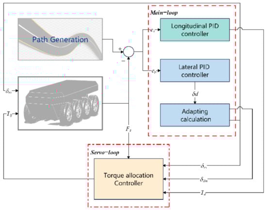
Figure 1.
Diagram of the overall control scheme.
2. Control-Oriented Vehicle Dynamics Modeling
For superior off-road maneuverability, an eight in-wheel motor-driven unmanned vehicle with a rear-wheel steering mechanism (8WD/RWS) is designed in this paper. The overall arrangement is a diesel–electric drive paradigm consisting of eight in-wheel motor driving units, the DC/DC converter, battery package, generator, and diesel engine modular. As shown in Figure 2, the diesel engine works at constant power for electricity generation, recharging the battery. The in-wheel motors are powered by the battery. Therefore, in this paper, the 8WS/RWS is regarded as a pure electric vehicle for energy management study, neglecting the dynamic characteristics and working efficiency of the diesel engine. Ignoring the effect of the suspension, and assuming that the yaw center coincides with the center of mass, a control-oriented dynamic model is established as an object with 13 degrees of freedom (DOF). The full 8WD/RWS model contains three DOF for translation and rotation of the vehicle body, eight tire dynamics, and two steering dynamics. According to the force schematic shown in Figure 2, the vehicle longitudinal dynamics equation can be expressed as:

Figure 2.
The overall configuration and force analysis diagram.
Similarly, the lateral dynamics and yaw dynamics equations can be represented by Equations (2) and (3), respectively:
where m is whole mass of the vehicle, , denote the vehicle longitudinal and lateral acceleration, respectively, r is the yaw rate, δrs is the rear-wheel steering angle, Fxij and Fyij represent the longitudinal and lateral force of eight wheels, respectively, li is the distance between the center of mass and the corresponding axle, and Iz refers to the yaw inertia moment. In addition, d stands for the wheel track, which is assumed all to be the same in this 8WD/RWS model.
To balance the control efficiency and precision, the lateral tire dynamics can be linearized into via local operating regime approximations, with cij denoting the tire cornering stiffness and αij denoting the slip angle for the corresponding tire. Based on the assumption of small angles, the tire slip angle of the steering wheel can be approximately written as:
The tire slip angle of non-steering wheel (j = 1; 2; 3) can be expressed as:
Then, appointing the lateral velocity vy and the yaw rate r as the system state variables, assuming that rs is relatively small and neglecting the difference between the left and right wheel, the further simplified model can be rewritten as:
where δrs is the external direct moment equivalent angle.
3. The Cascade Controller Design
3.1. The Main Loop Controller
The main loop controller is constructed to determine the overall vehicle longitudinal torque and yaw motion demand, while leaving the complex non-linear characteristics down to the servo-loop controller. Considering the merits of robustness and simplicity for application, two tuned PID controllers are designed to track the desired longitudinal torque and yaw rate. For the longitudinal controller, a proportion-integral (PI) structure is synthesized according to the error of longitudinal velocity:
where Td is the total demanded drive torque.
As for the lateral tracking, a fusion-error PI controller for aiming pursuit control is established based on the frame presented in [21]:
where δed, θeref, and θe represent the equivalent demanding steering angle, the target heading angle, and the equivalent actual heading angle, respectively.
Since is difficult to generate efficient turning motion using only the steering wheel on the rear axle in the 8WD/RWS vehicle, the equivalent demanding steering angle is decomposed into rear-wheel steering angle δrs and direct moment equivalent angle δdm by the adapting calculation module, which can adaptively adjust the intervention level of the direct yaw moment to make an efficient turning motion. The adapting ratio is calculated utilizing a second-order smooth polynomial:
with , and is the maximum steering angle. It is of note that the direct moment equivalent angle dm is converted into direct yaw moment Mzd in the servo loop controller for optimal torque allocation.
3.2. The Servo Loop Controller
The servo loop controller is designed to optimize the distribution of the tractive torques for achieving the demanding tractive force and external yaw moment, considering the various physical constraints and complex tire force properties.
The control intents of the servo loop controller are to minimize torque allocation error and regulate allocated tire forces in proportion to the capacity of a friction circle that changes based on the available vertical load of each tire. It is of note that a friction circle denotes the maximum tire force that can be provided by individual wheel. The performance cost function can be defined as an association of control inputs error J1, tire vertical force friction circle J2, and weighting factors W1, W2:
with the control effectiveness matrix B:
the control inputs u:
the control output expectation vd:
the objective weighting matrix W1, W2
Then, the torque allocation can be solved by using the QP approach with the constraints of vertical loads and the road adhesion condition, as well as the forces saturation and changing rate of in-wheel motors:
4. Numerical Simulation and Results Analysis
A co-simulation environment containing TruckSim, and MATLAB/Simulink is established to contrast the convergences and robustness of the cascade controller.
Under the co-simulation frame, the cascade controller was established based on Simulink, while the TruckSim model serves as the control object. Based on the 8WD/RWS prototype developed by NOVERI, the corresponding visualization model, as well as the off-road driving scenario, were customized utilizing SolidWorks and TruckSim, as shown in the right of Figure 3. The overall scenario was a circular cross-country road with a radius of 100 m. To verify the robustness of the controller, the circle was divided into four sub-scenarios including rough road scenario, up and down hilly scenario, variable adhesion scenario, and at road scenario, as shown in Figure 3. In addition, the ground elevation trending is marked in Figure 4, and the specifications used in the controller design and following co-simulations are listed in Table 1.

Figure 3.
The off-road surface geometry partition.
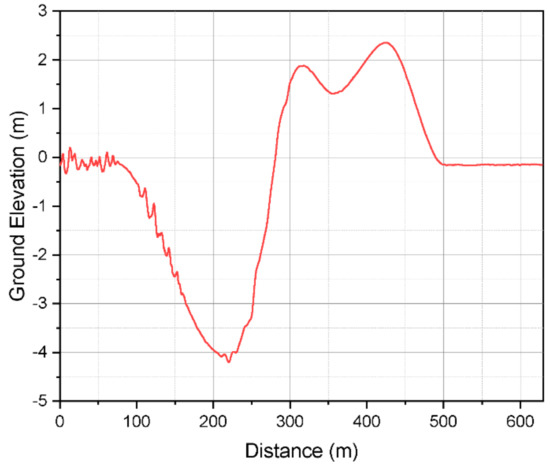
Figure 4.
The ground elevation of the scenario.

Table 1.
Key parameters for co-simulation.
To verify the optimization effect of the proposed torque allocation algorithm, an equal allocation algorithm was set as the comparison object. The comparative results of tracking performance are presented in Figure 5, in which the DYM_O represents the optimized allocation results, and the DYM_E represents the equal allocation results. As indicated in Figure 5b, the maximum error occurs in the rough road stage, since the undulating terrain prevents the precise attitude adjustment for path tracking. As for the DYM_E algorithm, the maximum error is about 1.25 m for rough roads, whereas the maximum value is around 0.6 m with the DYM_O algorithm. During the road stage, all the algorithms perform well, with a maximum error of about 0.1 m, since there are fewer external disturbances compared to the other stages.

Figure 5.
The tracking performance comparison. (a) tracking performance comparison; (b) tracking error comparison.
For a further investigation of the control performance, the torque allocation status and vehicle motion attitudes, as well as tire forces, are compared in Figure 6, Figure 7, Figure 8, Figure 9 and Figure 10. Figure 6 shows the torque allocation contradistinction results for the two algorithms. Since tires on the same side share the equal torque allocation for DYM_E, the allocation results only have two variables: L_E for the left side and R_E for the right side. Lx_O and Rx_O represent the torque allocation for DYM_E. Figure 7 and Figure 8 illustrate the comparison of vehicle control stability performances from the perspective of vehicle attitudes and accelerations. Combined with Figure 6, it can be seen that the application of optimal torque allocation can reduce the roll angle and pitch angle, as well as related accelerations, to a degree. The comparison indicates that the proposed torque allocation algorithm could better stabilize the vehicle during off-road maneuvering.

Figure 6.
The comparison of tractive torque allocation.

Figure 7.
The comparison of roll status: (a) roll angle status; (b) roll acceleration status.

Figure 8.
The comparison of pitch status: (a) pitch angle status; (b) pitch acceleration status.

Figure 9.
The comparison of lateral forces: (a) lateral forces for 1st and 2nd axles; (b) lateral forces for 3rd and 4th axles.

Figure 10.
The comparison of vertical forces: (a) vertical forces for 1st and 2nd axles; (b) vertical forces for 3rd and 4th axles.
Figure 9 and Figure 10 demonstrate the contrastive results of lateral and vertical forces for the individual tire. It can be seen from Figure 9 that in the same location, the maximum tire force with DYM_O is lower compared with DYM_E. The divergence is more prominent (approximately 8%) for the vertical forces, suggesting an optimal tire force utilization rate and a more considerable stable margin for complicated terrain maneuverability.
5. Conclusions
In this paper, a cascade control system with dual loops is proposed to enhance the stability and maneuverability of an unmanned 8WD/RWS prototype via a direct yaw moment control approach, taking advantage of the configuration superiority.
In the main loop, the desired drive moment and yaw rate are regulated via PID controllers. In the servo loop, the optimal torque distribution is calculated utilizing QP considering the tire force friction circle. The response of the 8WD/RWS with the cascade control was evaluated via co-simulation using TruckSim and MATLAB under an off-road maneuvering scenario. Simulation results show that the maneuverability and stability of the proposed controller are better than that of the equal allocation controller concerning the yaw rate, lateral position error, vehicle body attitude, and tire force utilization rate, since the proposed control frame can optimally allocate the tire torque output to make a bigger stability margin and better control effect. In our future work, a real-world test platform with CDYC will be built to further improve the performance of the proposed control architecture in complex off-road environments.
Author Contributions
Conceptualization, S.T. and T.L.; methodology, S.T., W.C. and Y.W.; validation, S.L. and B.P.; formal analysis, B.P.; investigation, S.T.; writing—original draft preparation, S.T. and W.C.; writing—review and editing, S.T. and N.Z.; visualization, S.T.; supervision, Y.W. and X.C. All authors have read and agreed to the published version of the manuscript.
Funding
This research received no external funding.
Data Availability Statement
The data are not publicly available due to business privacy restrictions, however, the data presented in this study could be available on request from the corresponding author.
Conflicts of Interest
The authors declare no conflict of interest.
References
- Yin, G.D.; Jin, X.J.; Zhang, Y. Overview for chassis vehicle dynamics control of distributed drive electric vehicle. J. Chongqing Univ. Technol. 2016, 30, 13–19. [Google Scholar]
- Kumar, M.S.; Revankar, S.T. Development scheme and key technology of an electric vehicle: An overview. Renew. Sustain. Energy Rev. 2017, 70, 1266–1285. [Google Scholar] [CrossRef]
- Luo, T.; Su, B.; Zhang, N.; Tan, S. A control allocation strategy of multi-axle unmanned distributed drive vehicle. In Proceedings of the 2021 2nd International Conference on Artificial Intelligence and Computer Engineering (ICAICE), Hangzhou, China, 5–7 November 2021. [Google Scholar]
- Jackson, A.; Crolla, D.; Woodhouse, A.; Parsons, M. Improving Performance of a 6 × 6 Off-Road Vehicle through Individual Wheel Control; SAE Technical Paper No. 2002-01-0968; SAE International: Warrendale, PA, USA, 2002; pp. 2–3. [Google Scholar]
- Goodarzi, A.; Esmailzadeh, E. Design of a VDC System for All-Wheel Independent Drive Vehicles. IEEE/ASME Trans. Mechatron. 2007, 12, 632–639. [Google Scholar] [CrossRef]
- Geng, C.; Mostefai, L.; Denai, M.; Hori, Y. Direct Yaw-Moment Control of an In-Wheel-Motored Electric Vehicle Based on Body Slip Angle Fuzzy Observer. IEEE Trans. Ind. Electron. 2009, 56, 1411–1419. [Google Scholar] [CrossRef]
- Kim, W.; Yi, K.; Lee, J. Drive control algorithm for an independent 8 in-wheel motor drive vehicle. J. Mech. Sci. Technol. 2011, 25, 1573–1581. [Google Scholar] [CrossRef]
- Yim, S. Coordinated control with electronic stability control and active steering devices. J. Mech. Sci. Technol. 2015, 29, 5409–5416. [Google Scholar] [CrossRef]
- Jin, X.J.; Yin, G.; Chen, N. Gain-scheduled robust control for lateral stability of four-wheel-independent-drive electric vehicles via linear parameter-varying technique. Mechatronics 2015, 30, 286–296. [Google Scholar] [CrossRef]
- Kim, C.J.; Mian, A.A.; Kim, S.H.; Back, S.H.; Jang, H.B.; Jang, J.H.; Han, C.S. Performance evaluation of integrated control of direct yaw moment and slip ratio control for electric vehicle with rear in-wheel motors on split-mu road. Int. J. Automot. Technol. 2015, 16, 939–946. [Google Scholar] [CrossRef]
- Ren, B.; Chen, H.; Zhao, H.; Yuan, L. MPC-based yaw stability control in in-wheel-motored EV via active front steering and motor torque distribution. Mechatronics 2016, 38, 103–114. [Google Scholar] [CrossRef]
- Guo, J.; Luo, Y.; Li, K. An Adaptive Hierarchical Trajectory Following Control Approach of Autonomous Four-Wheel Independent Drive Electric Vehicles. IEEE Trans. Intell. Transp. Syst. 2017, 19, 2482–2492. [Google Scholar] [CrossRef]
- Yue, S.; Fan, Y. Hierarchical Direct Yaw-Moment Control System Design for In-Wheel Motor Driven Electric Vehicle. Int. J. Automot. Technol. 2018, 19, 695–703. [Google Scholar] [CrossRef]
- Wang, Y.; Zhao, X.; Li, S.; Su, B.; Gao, J. Path tracking of eight in-wheel driving autonomous vehicle: Controller design and experimental results. In Proceedings of the 2019 IEEE International Conference on Unmanned Systems (ICUS), Beijing, China, 17–19 October 2019. [Google Scholar]
- Nah, J.; Yim, S. Vehicle Stability Control with Four-Wheel Independent Braking, Drive and Steering on In-Wheel Motor-Driven Electric Vehicles. Electronics 2020, 9, 1934. [Google Scholar] [CrossRef]
- Liu, D.; Huang, S.; Wu, S.; Fu, X. Direct Yaw-Moment Control of Electric Vehicle with in-Wheel Motor Drive System. Int. J. Automot. Technol. 2020, 21, 1013–1028. [Google Scholar] [CrossRef]
- Cheng, S.; Li, L.; Liu, C.-Z.; Wu, X.; Fang, S.-N.; Yong, J.-W. Robust LMI-Based H-Infinite Controller Integrating AFS and DYC of Autonomous Vehicles with Parametric Uncertainties. IEEE Trans. Syst. Man Cybern. Syst. 2020, 51, 6901–6910. [Google Scholar] [CrossRef]
- He, Y.; King, I.; Britam, E.; Cai, Y.; Yuan, C. Design and analysis of robust state constraint control for direct yaw moment control system. Int. J. Model. Simul. 2021, 42, 551–560. [Google Scholar] [CrossRef]
- Seo, Y.; Cho, K.; Nam, K. Integrated Yaw Stability Control of Electric Vehicle Equipped with Front/Rear Steer-by-Wire Systems and Four In-Wheel Motors. Electronics 2022, 11, 1277. [Google Scholar] [CrossRef]
- Liu, H.; Liu, C.; Han, L.; Xiang, C. Handling and Stability Integrated Control of AFS and DYC for Distributed Drive Electric Vehicles Based on Risk Assessment and Prediction. IEEE Trans. Intell. Transp. Syst. 2022, 1–16, Early Access. [Google Scholar] [CrossRef]
- Tan, S.; Zhao, X.; Yang, J.; Zhang, W. A path tracking algorithm for articulated vehicle: Development and simulations. In Proceedings of the 2017 IEEE transportation electrification conference and expo, Asia-Pacific (ITEC Asia-Pacific), Harbin, China, 7–10 August 2017. [Google Scholar]


Publisher’s Note: MDPI stays neutral with regard to jurisdictional claims in published maps and institutional affiliations. |
© 2022 by the authors. Licensee MDPI, Basel, Switzerland. This article is an open access article distributed under the terms and conditions of the Creative Commons Attribution (CC BY) license (https://creativecommons.org/licenses/by/4.0/).