Article

Outage Probability and BER Estimation for FSO Links with Truncated Normal Time Jitter and Longitudinal Gaussian Pulse Propagation in Dispersive Media

by
Panagiotis J. Gripeos
1,
Dimitrios Kriempardis
1,
Konstantinos Aidinis
2,3 and
Hector E. Nistazakis
1,*
1
Section of Electronic Physics and Systems, Department of Physics, National and Kapodistrian University of Athens, 15784 Athens, Greece
2
Department of Electrical and Computer Engineering, Ajman University, Ajman P.O. Box 346, United Arab Emirates
3
Centre of Medical and Bio-Allied Health Sciences Research (CMBHSR), Ajman University, Ajman P.O. Box 346, United Arab Emirates
*
Author to whom correspondence should be addressed.
Electronics 2022, 11(19), 2981; https://doi.org/10.3390/electronics11192981
Submission received: 12 August 2022 / Revised: 11 September 2022 / Accepted: 15 September 2022 / Published: 20 September 2022
(This article belongs to the Section Microwave and Wireless Communications)

Abstract

:
FSO is one of the most widespread, low-cost, wireless, optical communicational technologies with sufficiently high throughput, transmission reliability, and high-level security. Nevertheless, many fading effects act on the optical pulses used, during their propagation, causing performance degradation. In this work, group velocity dispersion and time jitter, modeled by the truncated normal distribution, are jointly investigated analytically and numerically. The availability of the studied model is expressed in terms of outage probability, while its reliability is given in terms of its average bit error rate, through the derived novel mathematical expressions. To the best of authors’ knowledge, this is the first time that the outage and the BER performance are estimated analytically, through specific approximations, taking into account the abovementioned physical effects. Furthermore, using the obtained mathematical forms, the corresponding numerical results are presented by assuming typical parameter values for realistic FSO links.

1. Introduction

Free space optical (FSO) communications represent one of the most widespread, low-cost, wireless optical communicational technologies around the world, with sufficiently high throughput, transmission reliability, and conversation eavesdropping security [1,2,3,4,5,6,7,8,9,10,11,12]. FSO systems are implemented using cheap and easy-to-setup equipment, minimizing the installation and maintenance costs. Moreover, FSO links operate in the unlicensed and harmless-to-humans infrared band of the electromagnetic spectrum, making FSO systems attractive [13,14,15,16,17,18,19]. Nevertheless, since light pulses propagate through the diverse atmosphere, they suffer from many degrading effects, leading to fading signal issues at the receiver’s end. The best way to overcome these issues is to identify each influencing factor and then understand their behavior, studying them individually or jointly, by changing the current weather conditions. In addition, the system’s specifications, including the length and the bit rate of a studied link, are also determining factors of its performance, because many effects act instantly and cumulatively, along the propagation path. In this work, the group velocity dispersion (GVD) and the time jitter (TJ) were investigated as a joint effect on longitudinal Gaussian pulses traveling through the dispersive atmosphere. It is worth noting that the scintillation effect, caused by atmospheric turbulence, has a significant effect on FSO propagation [1,2,3,4,5,6,7,8,9,10,11,12,13,14,15,20], which deserves to be studied jointly with GVD and TJ, in a future study.
In particular, the GVD is a known effect acting on signals consisting of many frequency (or wavelength equivalently) components, which travel at different speeds, resulting in a pulse shape flattening in the time domain, implying a signal degradation, along its propagation [21,22]. Hence, in this context, the link’s length is an important parameter. The bit rate is also important, because the corresponding detection timeslot sets a tolerance limit, beyond which adjacent pulses are overlapped, inducing inter-symbol interference (ISI) [23,24,25].
Furthermore, the TJ can be caused by any kind of transmission or detection delays that keep the transmitter and receiver out of sync. Under these circumstances, the peak of the incoming pulse does not coincide with the center of the dedicated timeslot. In other words, supposing that the detection is ideally performed at the center of timeslot, the amplitude of the instantly receiving signal is surely lower than the pulse’s peak, inferring a fading effect. Again, the timeslot duration is especially critical in the case of a strong TJ effect, where the leading or lagging incoming pulse can be misdetected even in adjacent timeslots, causing eventual bit flips, which could disorder the bit-stream [26,27,28,29]. Such problems can be efficiently solved by employing forward error correction (FEC) coding techniques [7,30].
In this study, the FSO link was assumed to be implemented via longitudinal Gaussian pulses, subject to GVD and a weak-to-moderate TJ effect, modeled by the truncated normal distribution, implying that the TJ effect creates uncertainty at the bit detection time, which is assumed to remain on its own timeslot. Studies and techniques facing strong TJ cases have been analyzed (e.g., in [31]). The availability of the studied model is expressed in terms of outage probability (OP), while its reliability is obtained in terms of its average bit error rate (ABER) performance.
The remainder of this work is organized as follows: Section 2 contains the model analysis toward the generation of a compact mathematical expression of a joint probability density function (PDF) of the involved phenomena. In Section 3, the mathematical expressions for the performance quantities are derived, while the numerical results from the obtained equations are discussed in Section 4, and the study conclusions are hosted in Section 5.

2. System Model

The proposed model is valid for a dispersive, stationary, memoryless, and ergodic channel with independent and identically distributed (i.i.d.) intensity fading statistics. In that case, the electrical signal, received, r, can be expressed as follows [20,32,33]:
r = x s + n ˜ = x η I + n ˜ ,
where x modulates the signal bit, as “0” or “1”, s denotes the instantaneous beam intensity, η is the effective photo-current conversion ratio of the receiver, I represents the normalized signal irradiance, and n ˜ is the additive white Gaussian noise (AWGN), of zero mean value and variance equal to N 0 / 2 , with N0 being the noise power density [34].

2.1. Chromatic Dispersion Effect

In this work, it is assumed that the FSO link under consideration uses a simple modulation format such as on/off keying (OOK) modulation with non-return-to-zero (NRZ) pulses which can be approximated using those with a Gaussian profile. Due to the fact that the signal propagates as a longitudinal chirped Gaussian pulse envelope, with many spectral components which are traveling with different group velocities, the pulse amplitude, B, and pulse width, Tpw, evolve along the propagating distance, z, [8,22,35,36]. Thus, the instantaneous, normalized irradiance due to the GVD influence, I, is expressed as follows [22,37,38]:
I = B exp T / T p w 2 ,
where T is the retarded time, which is defined in the usual way, for many physical models [37], and T = 0 describes the center of the pulse at any point of the link path, B z = 1 + 2 T 0 2 C β 2 z + T 0 4 C 2 + 1 β 2 2 z 2 1 / 2 and T p w z = T 0 2 + 2 C β 2 z + T 0 2 C 2 + 1 β 2 2 z 2 1 / 2 ,where T0 is the pulse width at the transmitter’s origin (z = 0), C is the chirp parameter, where C = 0, C > 0, and C < 0 correspond to unchirped, up-chirped, and down-chirped pulses, respectively, and β 2 p s 2 / k m = 1.75 n ( ω ) P h π c 2 λ T h 1 × 10 15 is the GVD parameter, where n λ = 1 + 77.6 × 10 6 1 + 7.52 × 10 3 λ 2 P h / T h is the refractive index, ω r a d / s = 2 π × 10 6 υ λ 1 is the angular frequency, υ (m/s) is the speed of light in the medium, c is the speed of light in vacuum, λ (μm) is the operating wavelength, P h [ m b a r ] = 2.23 × 10 6 44.41 h × 10 3 5.256 and T h [ K ] = 288.19 6.49 × 10 3 h denote the pressure and the temperature conditions, respectively, and h (m) is the altitude of the studied horizontal terrestrial FSO link [22,37,38].
It is worth noting that down-chirped longitudinal Gaussian pulses are initially shrinking instead of spreading up to a critical distance, zc1, expressed as follows [37]:
z c 1 = C T 0 2 β 2 C 2 + 1 .
After that distance, the pulse spreads as an up-chirped one. The original dimensions of that pulse are restored at a second distance, zc2 = 2zc1, where I z = 0 , T = 0 = I z c 2 , 0 [37]. Figure 1 illustrates the time profile dispersion of the propagating pulse for opposite chirp parameters and various distances for a given wavelength.
Furthermore, the pulse amplitude and pulse width as a function of propagation distance, z, are depicted in Figure 2.

2.2. Time Jitter Effect

The TJ effect is a stochastic process, which can be described from a statistical distribution of the random value (RV) T, with mean value μT and variance σ T 2 , where the latter parameter corresponds to the TJ effect strength and the former corresponds to a systematic time shift either leading or lagging. As declared in the introduction, in this work, the TJ is modeled by the truncated normal distribution [37], which is expressed by the following PDF:
f T = 1 2 π σ T Φ T 2 Φ T 1 exp T μ T 2 2 σ T 2 , T 1 T T 2 ,
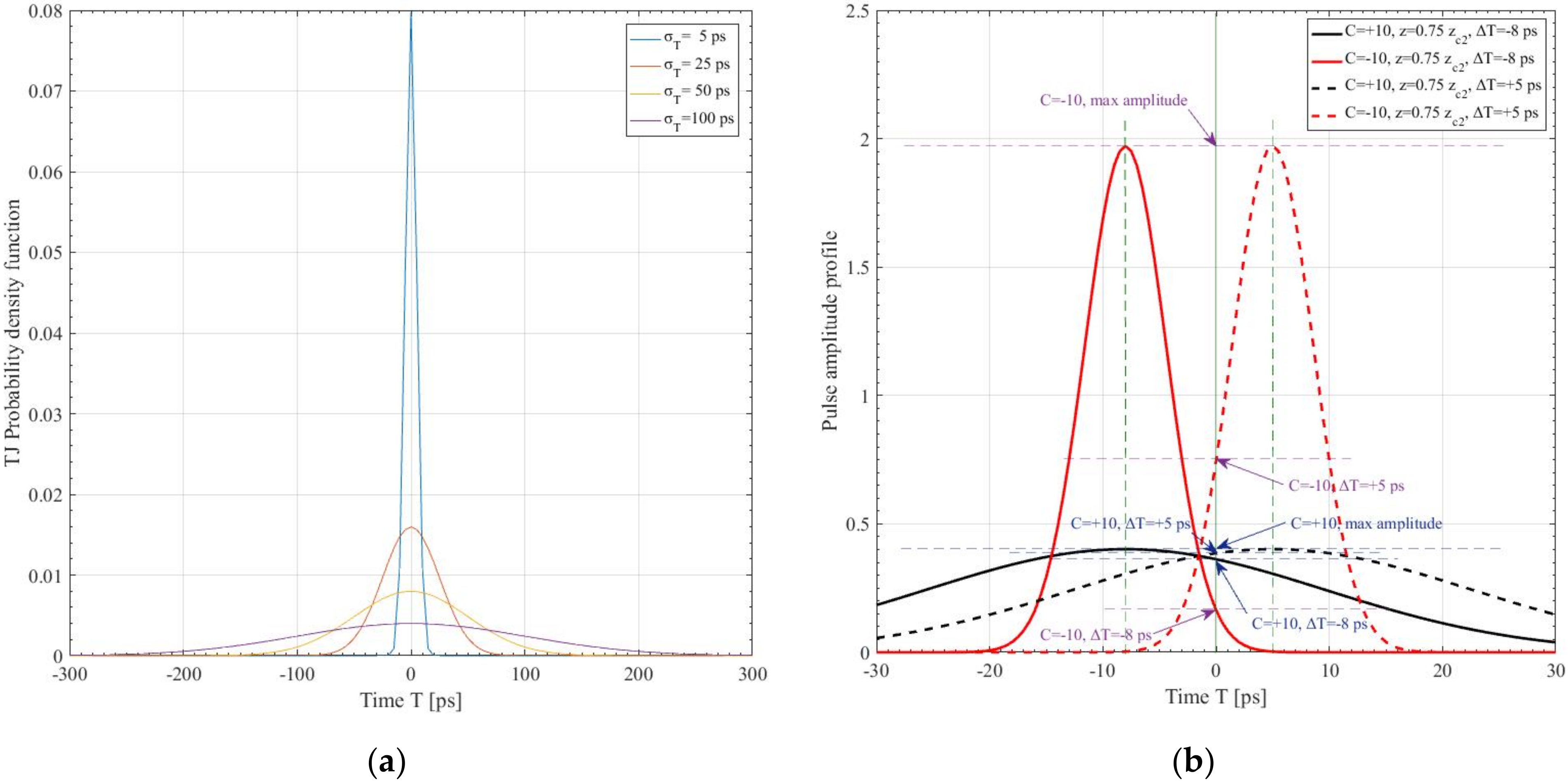
where Φ T i = 0.5 1 + e r f T i μ T / 2 σ T for i = 1, 2 indicates the truncated edges of the current timeslot. Assuming that TJ is symmetrically distributed around the timeslot center, without loss of generality, hereinafter the mean value of the TJ’s PDF is considered as zero (μT = 0). Figure 3a depicts the corresponding PDF curve as a function of T, for various TJ strength parameters. Figure 3b is a replica of Figure 1 for z = 0.75zc2, duplicated for two random jitters, ΔT= −8 and +5 ps. In both cases, the pulse amplitude received at the timeslot center (T = 0) is much lower than the maximum one at the pulse peak. In the latter case, the red curve is superior to the black one, whereas, in the former case, the reverse situation is valid, implying that the down-chirped pulses outmatch the up-chirped pulses only when the instantaneous TJ is relatively small, depending on the distance propagated.
The value of T is extracted from Equation (2), as a function of Ij, denoting the jitter influence on received irradiance.
T = ± T p w ln B / I j .
Considering the timeslot duration as Tsl, its edges lie at instants T = ± T s l / 2 ; hence, the irradiance value is bound between I j , min = B exp T s l / T p w 2 / 4 and B, which is the maximum irradiance at T = 0. Supposing the simplistic OOK modulation scheme, the bit rate, R, is related to the timeslot, as T s l , O O K = R 1 . Next, in order to estimate the joint PDF, an RV transformation has to be performed as follows:
f I j I j = f T ln B / I j d I j / d T T = + T p w ln B / I j + f T ln B / I j d I j / d T T = T p w ln B / I j .
Lastly, the PDF as a function of Ij, caused by the GVD and the TJ effect, is derived as follows:
f I j I j = T p w σ T Z 2 π ln B / I j I j exp T p w 2 ln B / I j 2 σ T 2 ,
where Z = Φ T 2 Φ T 1 .

2.3. Expected Irradiance Estimation

The next target is to estimate the expected value of the instantaneous, normalized irradiance, Ij. Remembering the possible limits within which irradiance can be detected, the RV expectation formula is adapted as follows [39]:
E I j = I j , min B I j f I j I j d I j .
In order to solve the integral above, y = T p w ln B / I j is used as the RV transformation, yielding the following expression:
E I j = 2 B 2 π σ T Z 0 y 0 exp y 2 1 T p w 2 + 1 2 σ T 2 d y ,
where y 0 = T s l / 2 . Finally, after some mathematical computations, we derive the following expression for the expected irradiance:
E I j = T p w B Z Ξ e r f Ξ T s l 2 T p w 2 σ T ,
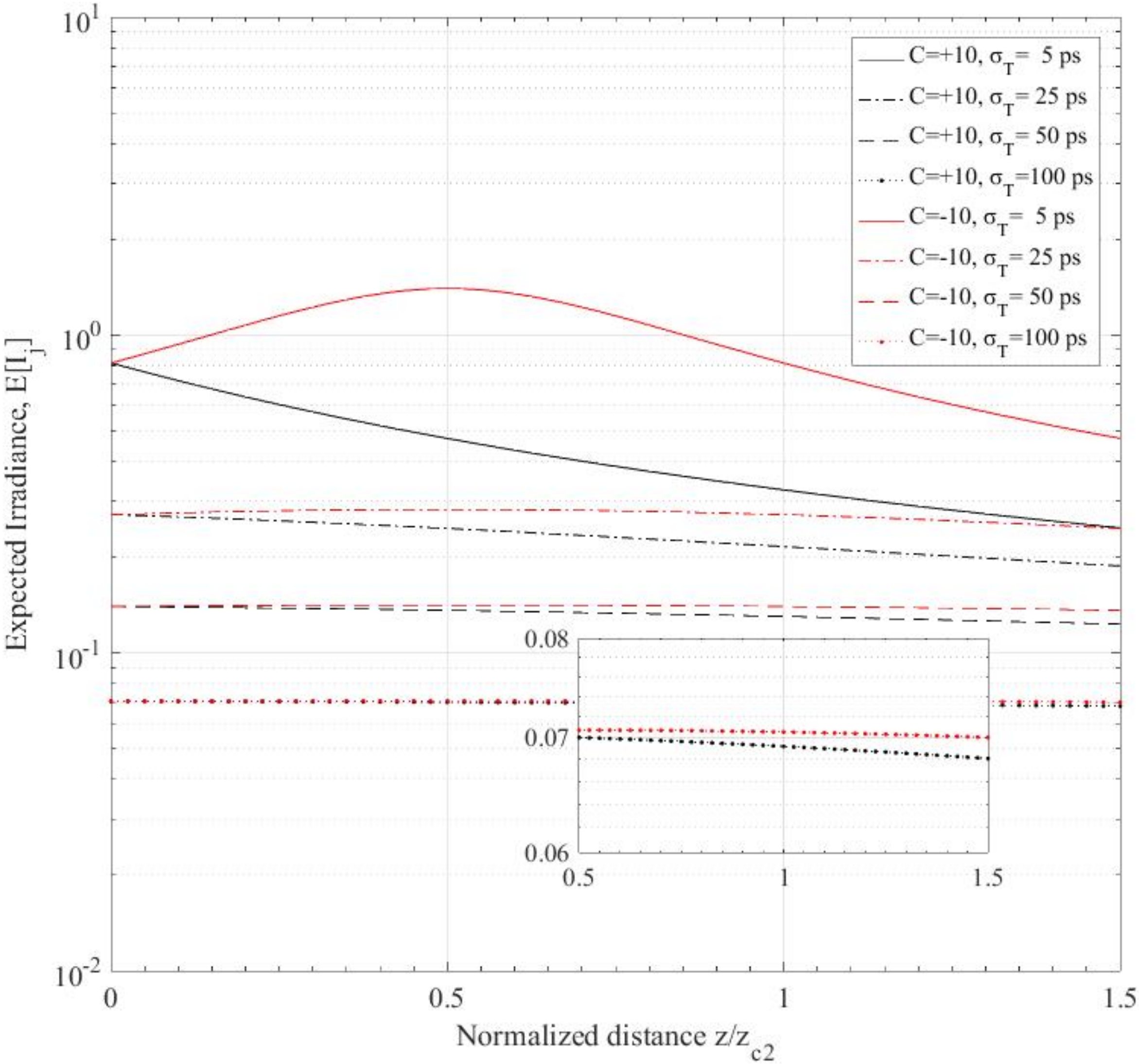
where Ξ = 2 σ T 2 + T p w 2 . Illustrations of the expected irradiance as a function of the propagation distance can be found in Figure 4, for various values of TJ strength parameter.

3. Performance of the Optical Wireless Link

From the link’s irradiance Ij, and Equation (1), the instantaneous signal-to-noise ratio (SNR) can be estimated as γ j = η I j 2 / N 0 [20,40], while the average SNR is given as γ ¯ j = η E I j 2 / N 0 . Thus, by using the appropriate RV transformation in Equation (7), the PDF for the instantaneous SNR is expressed as follows [20,40]:
f γ j γ j = T p w E I j 2 σ T Z γ j 2 π ln B γ ¯ j / γ j / E I j exp T p w 2 ln B γ ¯ j / γ j / E I j 2 σ T 2 .

3.1. Outage Probability Estimation

Consider a receiver that constantly measures the instantaneous SNR of the receiving pulses, provided that this value is larger than the sensitivity threshold, γj,th; otherwise, the link is thought to be interrupted. The probability of the link not being available is estimated through the OP [20,41,42,43,44,45], Pout, provided by the cumulative density function (CDF) of irradiance from the lowest possible SNR value, γ j , min γ j I j , min = B 2 γ ¯ j exp T s l 2 / 2 T p w 2 / E I j 2 , up to a given γj,th [20].
P o u t = F γ j γ j , t h = γ j , min γ j , t h f γ j γ j d γ j .
By substituting q = T p w ln B γ ¯ j / γ j / E I j , the above equation is transformed into
P o u t q t h = 2 2 π σ T Z q t h q 0 exp q 2 2 σ T 2 d q ,
where q 0 q γ j , min = T s l / 2 and q t h q γ j , t h = T p w ln B γ ¯ j / γ j , t h / E I j . Then, the OP in terms of average SNR and for a certain SNR threshold is simply generated as follows:
P o u t γ ¯ j ; γ j , t h = 1 Z e r f T s l 2 2 σ T e r f T p w ln B γ ¯ j / γ j , t h / E I j 2 σ T .

3.2. Average Bit Error Rate Estimation

Another significant metric quantity that measures the reliability of the system is the frequency of bit errors occurring per time unit, known as the bit error rate (BER). Supposing that the link supports the NRZ-OOK modulation scheme, the respective instantaneous BER is expressed as follows [15,44,45]:
P e ( I j ) = 1 2 e r f c 2 η I j 4 N 0 P e ( γ j ) = 1 2 e r f c 2 γ j 4 ,
where erf(.) denotes the complementary error function [46].
However, the average BER (ABER) of the link is more preferable than the instantaneous one, since the former provides a clear, durable picture of the operating FSO system. The ABER is computed as the expectation of the instantaneous irradiance between Ij,min and B or, equivalently, of the instantaneous BER between the minimum, γj,min, and the maximum SNR, γ j , max γ j ( B ) = B 2 γ ¯ j / E I j 2 , as follows [15,44,45]:
P ¯ e I j = I j , min B P I j f I j I j d I j P ¯ e γ ¯ j = 1 2 γ j , 0 γ j , max e r f c 2 γ j 4 f γ j γ j d γ j .
Then, by substituting erfc with e r f c ( x ) = 2 Q 2 x along with the Q-function approximation, Q ( x ) exp x 2 / 2 + 3 exp 2 x 2 / 3 / 12 , presented in [47], Equation (16) is approximated by
P ¯ γ ¯ j 1 6 2 π σ T Z 0 y 0 exp γ ¯ j B 2 8 E I j 2 exp 2 y 2 T p w 2 + 3 exp γ ¯ j B 2 6 E I j 2 exp 2 y 2 T p w exp y 2 2 σ T 2 d y .
Finally, using for the exponential function the power series of exp ( x ) = k = 0 x k / k ! , the following mathematical expression is obtained from ABER’s integral of Equation (17):
P ¯ e γ ¯ j T p w 12 Z k = 0 + 1 k ! Θ k γ ¯ j B 2 E I j 2 k 1 8 k + 3 6 k e r f Θ k T s l 2 2 T p w σ T ,
where Θ k = T p w 2 + 4 k σ T 2 .

4. Numerical Results

It is assumed that the studied terrestrial horizontal FSO link operates at λ = 1.55 μm, 30 m above the ground, while the absolute chirp value is fixed to |C| = 10, either positive or negative, and its throughput is R = 100 Mbps. In the below numerical results and figures, all positive chirp cases are depicted with black curves, while the red ones are related to the negative chirp cases. Furthermore, the pulse width at the transmitter, T0, is fixed to either 6 or 10 ps, whereas the TJ parameter, σT, is assumed to be 5, 25, 50, or 100 ps.
The pulse profiles of both up-chirped and down-chirped pulses after various distances for the origin are shown in Figure 1. Furthermore, the pulse amplitude and pulse width, as a function of the propagating distance, for the same parameter value combinations, are illustrated in Figure 2. It is clear that the down-chirped pulses have maximum amplitude and minimum pulse width at the same point, varying according to the original pulse width value. A larger original pulse width results in further maximization/minimization of the respective quantity. Moreover, the gradient of the amplitude/pulse width change is smoother for a larger original pulse width in any studied case.
Furthermore, the PDF used for the TJ effect is plotted in Figure 3 for the studied strength parameters, with the narrower curve corresponding to the smallest strength value and the wider curve corresponding to the larger one. Note that the time slot edges in this case, i.e., ±5 ns, are much wider than any studied TJ parameter and, for that reason, they are not shown in the plot.
Next, in Figure 4, the expected irradiance is plotted as a function of the normalized propagation distance, z/zc2. It can be easily inferred that the cases corresponding to a small TJ parameter have larger expected irradiance values, while the large TJ parameter cases demonstrate lower expected irradiance. Furthermore, the up-chirped pulse curves steadily decrease, while the down-chirped pulse cases demonstrate a maximum at the first critical distance. The difference between the opposite chirp cases depends on the TJ strength. Indeed, stronger TJ cases are hardly distinguished at short and long distances.
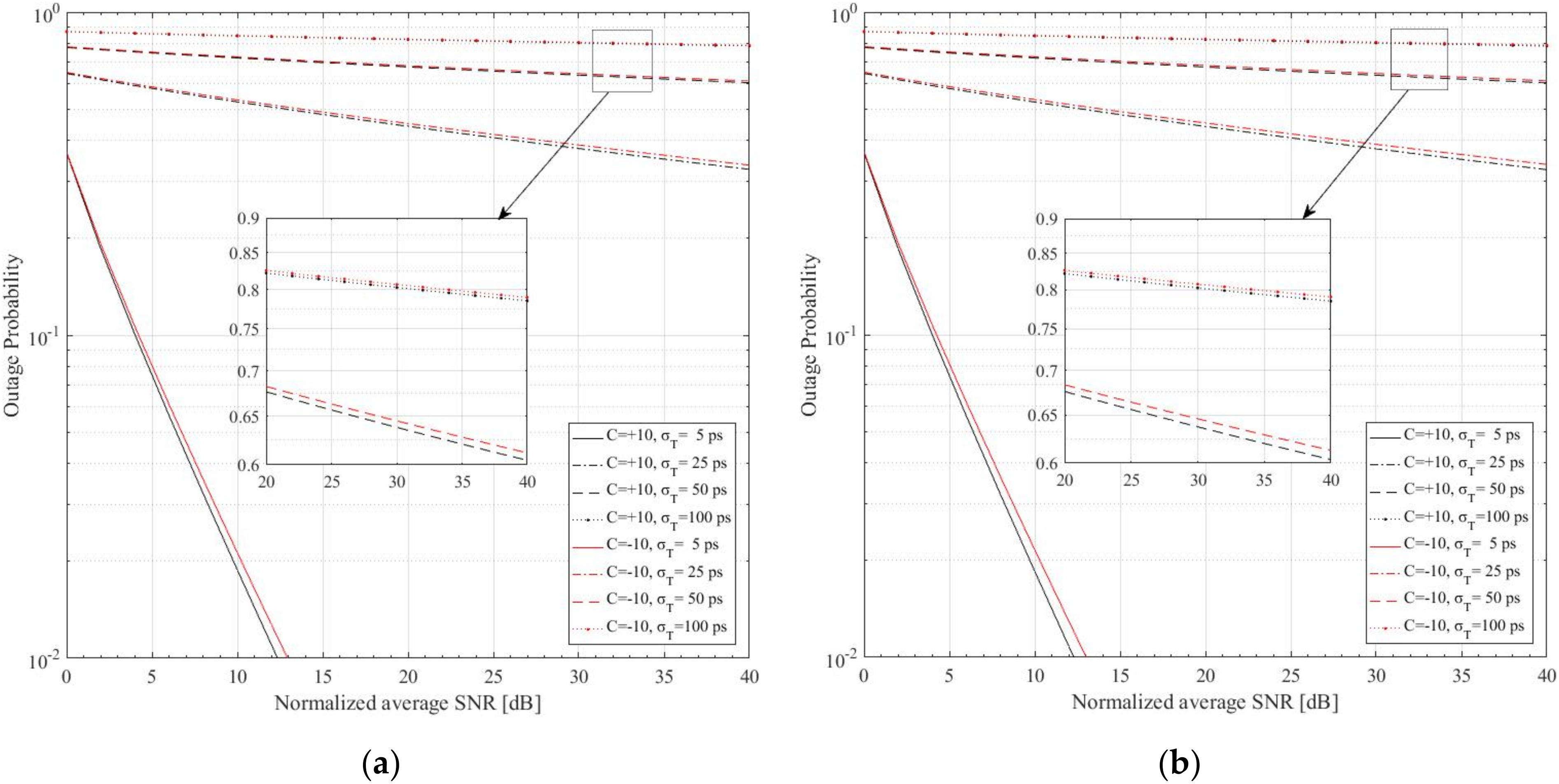
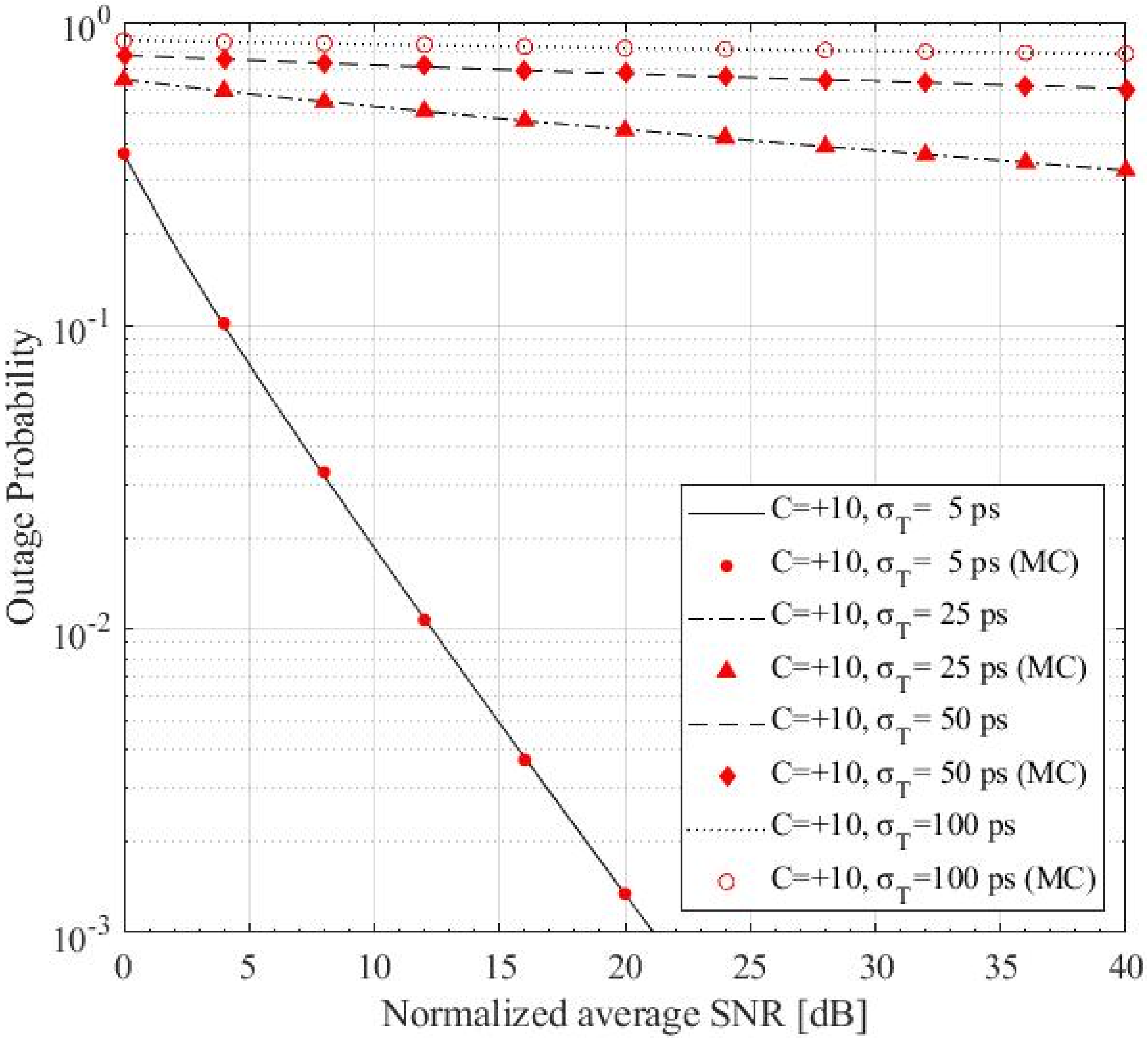
Furthermore, Figure 5 depicts the OP as a function of the normalized average SNR, γ ¯ j / γ j , t h , as detected at 8 km and 10 km propagation distance. It is clear that, in any studied case, the curves decline for larger normalized average SNR values, confirming that signals with higher normalized average SNR face fewer outage occurrences. Furthermore, up-chirped cases have lower OP than down-chirped cases. In addition, curves with a weaker TJ effect are steeper than those with the opposite characteristics, implying lower OP at very large normalized average SNR. Some of the numerical results illustrated were verified using the Monte Carlo (MC) method, as shown in Figure 6, for the up-chirped cases after 10 km. The MC results are sufficiently compatible with the respective numerical results after 107 steps, reinforcing the integrity of the presented equations.
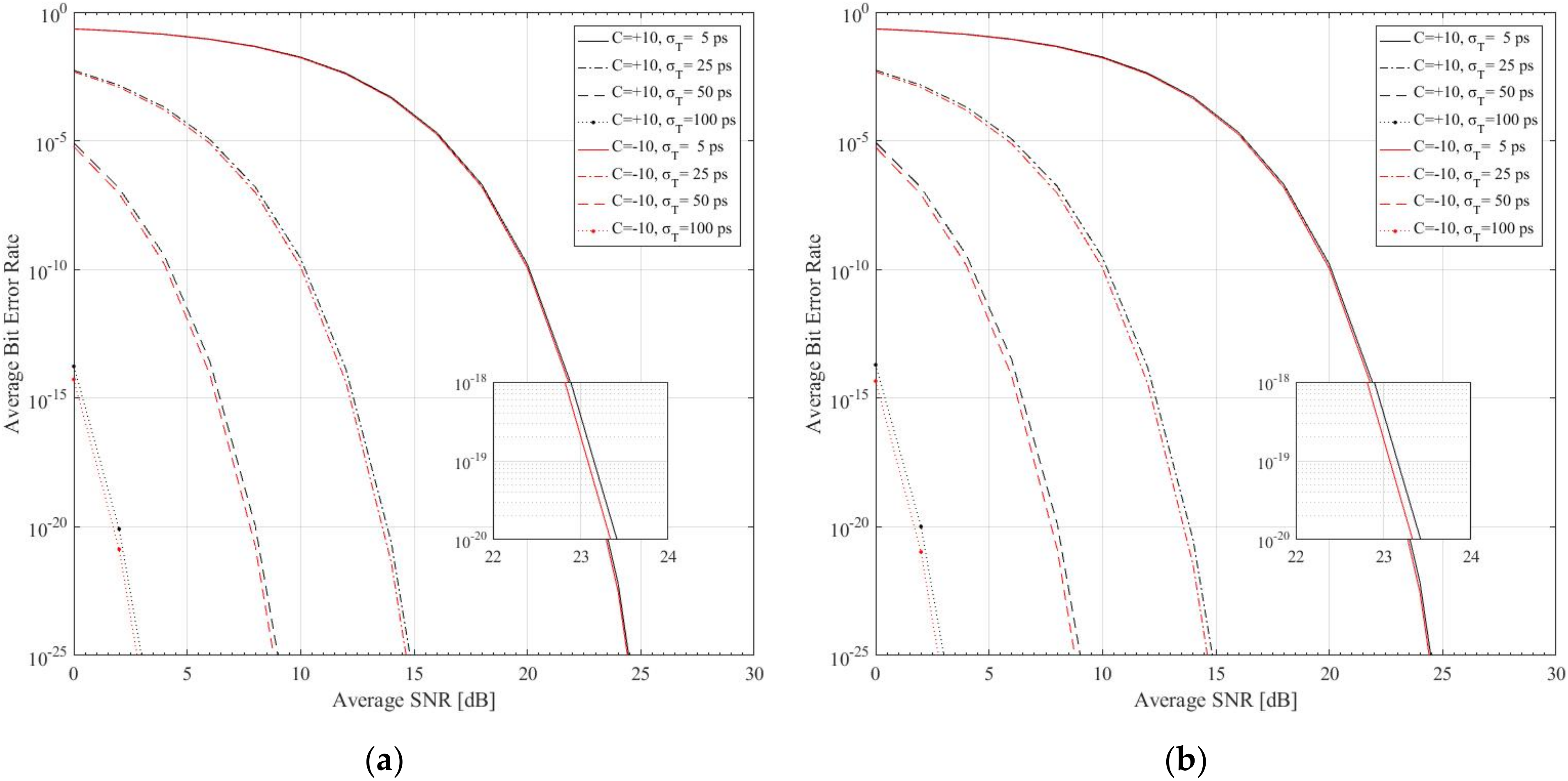
Figure 7 illustrates the corresponding average BER curves, as a function of the average SNR, as detected after 8 km and 10 km. The first note is that all curves gradually declined with the increase in average SNR, implying more reliable links for larger SNR values. The initial slope of each curve was determined by the TJ strength and the chirp parameter sign. In particular, a smaller TJ strength led to a smoother downfall slope. Additionally, red curves were always on the left of the corresponding black curves, with weaker TJ cases having little separation for opposite chirps.

5. Conclusions

In this work, the availability and the reliability of a terrestrial horizontal NRZ OOK FSO link implemented with optical, longitudinal, Gaussian pulses were estimated over dispersive atmospheric channels and a time-jitter effect, which was modeled using the truncated normal distribution. For this link, the average irradiance, the OP, and the ABER were analytically estimated, and the corresponding approximated mathematical expressions were derived for the first time according to the authors’ knowledge. Using the obtained mathematical forms, the corresponding numerical results were presented.

Author Contributions

Conceptualization, P.J.G., D.K. and H.E.N.; methodology, P.J.G. and H.E.N.; software, P.J.G. and H.E.N.; validation, P.J.G., D.K., K.A. and H.E.N.; formal analysis, P.J.G., D.K. and H.E.N.; investigation, P.J.G., D.K., K.A. and H.E.N.; resources, P.J.G. and H.E.N.; writing—original draft preparation, P.J.G. and H.E.N.; writing—review and editing, P.J.G., D.K., K.A. and H.E.N.; supervision, P.J.G., K.A. and H.E.N.; project administration, H.E.N. All authors have read and agreed to the published version of the manuscript.

Funding

This research received no external funding.

Data Availability Statement

Not applicable.

Conflicts of Interest

The authors declare no conflict of interest.

References

  1. Arnon, S. Optical Wireless Communications; Marcel Dekker Inc.: New York, NY, USA, 2003. [Google Scholar]
  2. Kedar, D.; Arnon, S. Urban optical wireless communication networks: The main challenges and possible solutions. IEEE Commun. Mag. 2004, 42, S2–S7. [Google Scholar] [CrossRef]
  3. Henniger, H.; Wilfert, O. An introduction to free-space optical communications. Radioengineering 2010, 19, 203–212. [Google Scholar]
  4. Ghassemlooy, Z.; Popoola, W.O. Terrestrial free-space optical communications. In Mobile and Wireless Communications Network Layer and Circuit Level Design; InTechOpen: London, UK, 2010. [Google Scholar]
  5. Erdogan, E.; Altunbas, I.; Kurt, G.K.; Yanikomeroglu, H. The Secrecy Comparison of RF and FSO Eavesdropping Attacks in Mixed RF-FSO Relay Networks. IEEE Photonics J. 2022, 14, 7901508. [Google Scholar] [CrossRef]
  6. Kaushal, H.; Kaddoum, G. Underwater Optical Wireless Communication. IEEE Access 2016, 4, 1518–1547. [Google Scholar] [CrossRef]
  7. Chi, Y.-C.; Hsieh, D.-H.; Tsai, C.-T.; Chen, H.-Y.; Kuo, H.-C.; Lin, G.-R. 450-nm GaN laser diode enables high-speed visible light communication with 9-Gbps QAM-OFDM. Opt. Express 2015, 23, 13051–13059. [Google Scholar] [CrossRef]
  8. Khajwal, T.N.; Mushtaq, A.; Kaur, S. Performance Analysis of FSO-SISO and FSO-WDM Systems under Different Atmospheric Conditions. In Proceedings of the 7th International Conference on Signal Processing and Integrated Networks (SPIN), Noida, India, 27–28 February 2020; pp. 312–316. [Google Scholar] [CrossRef]
  9. Ninos, M.P.; Nistazakis, H.E.; Tombras, G.S. On the BER performance of FSO links with multiple receivers and spatial jitter over gamma-gamma or exponential turbulence channels. Optik 2017, 138, 269–279. [Google Scholar] [CrossRef]
  10. Sandalidis, H.G.; Tsiftsis, T.A.; Karagiannidis, G.K.; Uysal, M. BER Performance of FSO Links over Strong Atmospheric Turbulence Channels with Pointing Errors. IEEE Commun. Lett. 2008, 12, 44–46. [Google Scholar] [CrossRef]
  11. Gappmair, W.; Hranilovic, S.; Leitgeb, E. Performance of PPM on terrestrial FSO links with turbulence and pointing errors. IEEE Commun. Lett. 2010, 14, 468–470. [Google Scholar] [CrossRef]
  12. Gappmair, W.; Muhammad, S.S. Error performance of PPM/Poisson channels in turbulent atmosphere with gamma-gamma distribution. Electron. Lett. 2007, 43, 880–882. [Google Scholar] [CrossRef]
  13. Tsiftsis, T.A.; Sandalidis, H.G.; Karagiannidis, G.K.; Uysal, M. Optical wireless links with spatial diversity over strong atmospheric turbulence channels. IEEE Trans. Wirel. Commun. 2009, 8, 951–957. [Google Scholar] [CrossRef] [Green Version]
  14. Kamalakis, T.; Sphicopoulos, T.; Muhammad, S.S.; Leitgeb, E. Estimation of the power scintillation probability density function in free-space optical links by use of multicanonical Monte Carlo sampling. Opt. Lett. 2006, 31, 3077–3079. [Google Scholar] [CrossRef]
  15. Bag, B.; Das, A.; Ansari, I.S.; Prokeš, A.; Bose, C.; Chandra, A. Performance Analysis of Hybrid FSO Systems Using FSO/RF-FSO Link Adaptation. IEEE Photonics J. 2018, 10, 7904417. [Google Scholar] [CrossRef]
  16. Esmail, M.A.; Ragheb, A.M.; Fathallah, H.A.; Altamimi, M.; Alshebeili, S.A. 5G-28 GHz Signal Transmission Over Hybrid All-Optical FSO/RF Link in Dusty Weather Conditions. IEEE Access 2019, 7, 24404–24410. [Google Scholar] [CrossRef]
  17. Wang, Z.; de Zhong, W.; Fu, S.; Lin, C. Performance comparison of different modulation formats over free-space optical (FSO) turbulence links with space diversity reception technique. IEEE Photonics J. 2009, 1, 277–285. [Google Scholar] [CrossRef]
  18. Majumdar, A.K. Advanced Free Space Optics (FSO)—A System Approach; Springer: Berlin/Heidelberg, Germany, 2015; Volume 140. [Google Scholar]
  19. Ahmed, M.S.; Gucluoglu, T. Performance of generalized frequency division multiplexing over gamma gamma free space optical link. Opt. Commun. 2020, 466, 125683. [Google Scholar] [CrossRef]
  20. Sandalidis, H.G.; Tsiftsis, T.A. Outage probability and ergodic capacity of free-space optical links over strong turbulence. Electron. Lett. 2008, 44, 46–47. [Google Scholar] [CrossRef]
  21. Lu, H.; Zhao, W.; Xie, X. Analysis of temporal broadening of optical pulses by atmospheric dispersion in laser communication system. Opt. Commun. 2012, 285, 3169–3173. [Google Scholar] [CrossRef]
  22. Agrawal, G. Nonlinear Fiber Optics; Elsevier: Amsterdam, The Netherlands, 2006. [Google Scholar]
  23. Lee, S.; Kavehrad, M. Free-Space Optical Communications with Channel Shortening Filter and Viterbi Equalizer. Int. J. Wirel. Inf. Netw. 2009, 16, 185–196. [Google Scholar] [CrossRef]
  24. Gupta, A.; Shaina, N. Modelling of 10 Gbps Free Space Optics Communication Link Using Array of Receivers in Moderate and Harsh Weather Conditions. J. Opt. Commun. 2017, 38, 293–296. [Google Scholar] [CrossRef]
  25. Zhang, D.; Hao, S.; Zhao, Q.; Wan, X.; Xu, C. Differential phase-shift keying and channel equalization in free space optical communication system. Opt. Eng. 2018, 57, 1. [Google Scholar] [CrossRef]
  26. Agrawal, G.P. Fiber-Optic Communication Systems, 4th ed.; Wiley: Hoboken, NJ, USA, 2011. [Google Scholar]
  27. Ghassemlooy, Z.; Arnon, S.; Uysal, M.; Xu, Z.; Cheng, J. Emerging Optical Wireless Communications—Advances and Challenges. IEEE J. Sel. Areas Commun. 2015, 33, 1738–1749. [Google Scholar] [CrossRef]
  28. Gonem, O.F.A.; Giddings, R.P.; Tang, J. Timing Jitter Analysis and Mitigation in Hybrid OFDM-DFMA PONs. IEEE Photonics J. 2021, 13, 7200313. [Google Scholar] [CrossRef]
  29. Mecozzi, A.; Clausen, C.B.; Shtaif, M.; Park, S.-G.; Gnauck, A.H. Cancellation of timing and amplitude jitter in symmetric links using highly dispersed pulses. IEEE Photonics Technol. Lett. 2001, 13, 445–447. [Google Scholar] [CrossRef]
  30. Hamming, R.W. Error Detecting and Error Correcting Codes. Bell Syst. Tech. J. 1950, 29, 147–160. [Google Scholar] [CrossRef]
  31. Roumelas, G.D.; Nistazakis, H.E.; Leitgeb, E.; Stassinakis, A.N.; Tombras, G.S. On the performance of optical wireless communication links impaired by time jitter, M-turbulence and pointing errors. Opt. Commun. 2020, 472, 126033. [Google Scholar] [CrossRef]
  32. Gappmair, W. Novel results on pulse-position modulation performance for terrestrial free-space optical links impaired by turbulent atmosphere and pointing errors. IET Commun. 2012, 6, 1300–1305. [Google Scholar] [CrossRef]
  33. Dimitrov, S.; Sinanovic, S.; Haas, H. Signal Shaping and Modulation for Optical Wireless Communication. J. Light. Technol. 2012, 30, 1319–1328. [Google Scholar] [CrossRef]
  34. Roumelas, G.D.; Nistazakis, H.E.; Stassinakis, A.N.; Varotsos, G.K.; Tsigopoulos, A.D.; Tombras, G.S. Time Jitter, Turbulence and Chromatic Dispersion in Underwater Optical Wireless Links. Technologies 2019, 8, 3. [Google Scholar] [CrossRef]
  35. Marcuse, D. Pulse distortion in single-mode fibers 3: Chirped pulses. Appl. Opt. 1981, 20, 3573–3579. [Google Scholar] [CrossRef]
  36. Santhanam, J.; Agrawal, G.P. Raman-Induced timing jitter in dispersion-managed optical communication systems. IEEE J. Sel. Top. Quantum Electron. 2002, 8, 632–639. [Google Scholar] [CrossRef]
  37. Stassinakis, A.N.; Nistazakis, H.E.; Peppas, K.P.; Tombras, G.S. Improving the availability of terrestrial FSO links over log normal atmospheric turbulence channels using dispersive chirped Gaussian pulses. Opt. Laser Technol. 2013, 54, 329–334. [Google Scholar] [CrossRef]
  38. Marcuse, D. Pulse distortion in single-mode fibers. Appl. Opt. 1980, 19, 1653–1660. [Google Scholar] [CrossRef]
  39. Varotsos, G.K.; Nistazakis, H.E.; Tombras, G.S. OFDM RoFSO Links with Relays Over Turbulence Channels and Nonzero Boresight Pointing Errors. J. Commun. 2017, 12, 644–660. [Google Scholar] [CrossRef]
  40. Zhu, X.; Kahn, J.M. Free-space optical communication through atmospheric turbulence channels. IEEE Trans. Commun. 2002, 50, 1293–1300. [Google Scholar] [CrossRef]
  41. Upadhya, A.; Dwivedi, V.K.; Karagiannidis, G.K. On the Effect of Interference and Misalignment Error in Mixed RF/FSO Systems Over Generalized Fading Channels. IEEE Trans. Commun. 2020, 68, 3681–3695. [Google Scholar] [CrossRef]
  42. Stassinakis, A.N.; Nistazakis, H.E.; Tombras, G.S. Comparative performance study of one or multiple receivers schemes for FSO links over gamma–gamma turbulence channels. J. Mod. Opt. 2012, 59, 1023–1031. [Google Scholar] [CrossRef]
  43. Khalid, H.; Muhammad, S.S.; Nistazakis, H.E.; Tombras, G.S. Performance Analysis of Hard-Switching Based Hybrid FSO/RF System over Turbulence Channels. Computation 2019, 7, 28. [Google Scholar] [CrossRef]
  44. Sandalidis, H.G. Optimization Models for Misalignment Fading Mitigation in Optical Wireless Links. IEEE Commun. Lett. 2008, 12, 395–397. [Google Scholar] [CrossRef]
  45. Roumelas, G.D.; Nistazakis, H.E.; Gappmair, W.; Gripeos, P.J.; Christofilakis, V. Time jitter influence on the performance of gamma–gamma turbulence FSO links with various modulation schemes. J. Mod. Opt. 2020, 67, 721–729. [Google Scholar] [CrossRef]
  46. Abramowitz, M.; Stegun, I.A.; Romer, R.H. Handbook of Mathematical Functions with Formulas, Graphs, and Mathematical Tables. Am. J. Phys. 1988, 56, 958. [Google Scholar] [CrossRef] [Green Version]
  47. Chiani, M.; Dardari, D.; Simon, M.K. New exponential bounds and approximations for the computation of error probability in fading channels. IEEE Trans. Wirel. Commun. 2003, 24, 840–845. [Google Scholar] [CrossRef] [Green Version]
Figure 1. Pulse irradiance profiles, I, overtime, for several propagation distances and chirp parameters.
Electronics 11 02981 g001
Figure 2. (a) The amplitude of the propagating pulse along z-axis, supposing the original amplitude equal to unity; (b) the corresponding pulse width evolution along z-axis.
Electronics 11 02981 g002
Figure 3. (a) Symmetric TJ PDF curves as a function of time T for various TJ strength parameter values. The corresponding timeslot of 100 Mbps is 10 ns, the edges of which are at T1 = +5 ns and T2 = −5 ns. (b) Time-jittered pulses for two random jitters, ΔT, and opposite chirp parameters. In any case, the pulse amplitude, received at instant T = 0, is much lower than the corresponding maximum pulse amplitude, as detected at z = 0.75 zc2.
Electronics 11 02981 g003
Figure 4. Expected irradiance of a pulse under the joint effect of GVD and TJ as a function of propagation distance ratio, z/zc2.
Electronics 11 02981 g004
Figure 5. Outage probability of a 100 Mbps link as a function of the normalized average SNR, γ ¯ j / γ j , t h , with T0 = 10 ps, as detected after (a) 8 km and (b) 10 km propagation distance.
Electronics 11 02981 g005
Figure 6. Outage probability of a 100 Mbps link as a function of the normalized average SNR, γ ¯ j / γ j , t h , with T0 = 10 ps, as detected after 10 km propagation distance. The illustrated curves are successfully contrasted with the Monte Carlo method with 107 steps, indicated by the corresponding red points.
Electronics 11 02981 g006
Figure 7. Average BER of a 100 Mbps link as a function of the average SNR, with T0 = 10 ps, as detected after (a) 8 km and (b) 10 km propagation distance.
Electronics 11 02981 g007
Publisher’s Note: MDPI stays neutral with regard to jurisdictional claims in published maps and institutional affiliations.