Article

Design and Experimental Study of a Curved Contact Quadrupole Railgun

1
Air Defense and Antimissle School, Air Force Engineering University, Xi’an 710043, China
2
Information and Navigation School, Air Force Engineering University, Xi’an 710043, China
*
Author to whom correspondence should be addressed.
Electronics 2022, 11(19), 3108; https://doi.org/10.3390/electronics11193108
Submission received: 29 August 2022 / Revised: 18 September 2022 / Accepted: 21 September 2022 / Published: 28 September 2022
(This article belongs to the Section Computer Science & Engineering)

Abstract

:
The railgun is a promising weapon, but suffers from poor contact and harsh magnetic field environment. We used the moment of inertia to measure the deformation resistance of the rail, studied the contact characteristics of the railgun by contact force, and compared the performances of different structures of the rail. The magnetic field environment in the bore and the thrust on the armature of different structure railguns were studied by FEM-BEM simulation, and the final structure of the hyperbolic augmented quadrupole railgun was determined. The new structure of the railgun possesses better deformation resistance and contact characteristics, and can provide an electromagnetic shielding area and greater thrust. The test results show that the proposed railgun exhibits less rail damage and less armature ablation after launch.

1. Introduction

The electromagnetic railgun is a device that can efficiently convert high-power electrical energy into kinetic energy in an instant [1,2,3]. Compared with the gunpowder launch method, the electromagnetic rail launch method has the advantages of high kinetic energy, high exit velocity, stable operation, good repeatability, precisely adjustable thrust, and short launch interval, according to Zhang B, Zeng D and Yu K [4,5,6,7], which is considered as the future direction of launch technology development in the military field. However, many problems have been encountered in the engineering process of railguns, mainly in (1) huge contact forces, great temperature changes causing armature and rail deformation, leading to contact failure [8,9,10]; (2) strong magnetic field during the operation of the railgun, leading to the poor electromagnetic compatibility of the equipment [11,12,13,14].
At present, researchers mainly improve the contact characteristics of railguns by enhancing the properties of rail materials. Xie H et al. reviewed the development of materials used for railguns in recent years; Lin Q. H et al. studied the damage caused by railgun operation and analyzed the plastic deformation and fatigue fracture of the rail through simulation [15]; Yao J studied the melting process of the rail and analyzed the effect of current and speed on the effect of the phase change of the rail [16]; Davidson G et al. improved traditional rail made of copper material to enhance the hardness of the rail [17]; Chen Y analyzed the sliding contact characteristics between the aluminum alloy armature and the rail of different materials [18]; Wen Y, Keshtkar et al. studied the effect of material properties on the electrical characteristics of the railgun [19,20]. The above studies have effectively improved the performance of railguns, but so far, they have not been able to completely solve the two main problems encountered in the engineering of railguns. In addition to enhancing material performance and improving the anti-electromagnetic interference capability of the equipment [21,22], improving the armature–rail contact effectiveness of the electromagnetic railgun and improving the bore magnetic field environment of the railgun through reasonable structural design is also an important direction for the development of the railgun [23,24,25,26].
Many scholars have made rich conclusions about the structural design of electromagnetic railguns. Kim B and Hai-yu Miao et al. studied the effect of different parameters of armature and rail overfill assembly on the initial contact characteristics of the railguns [25,27]; Teng-da Li and Hsieh et al. compared the effect of concave, convex and flat rails on the current distribution of railguns [24,28] and qualitatively analyzed its effect on the railgun performance; Shuai Li [29] et al. studied the effect of railgun caliber on the railgun performance Aigner S [9], Dalvi S [30], Chen J [31], Heydari [32], and Liu Y [33] proposed new structures such as a partially augmented railgun structure [34], spin armature railgun structure [32,35], quadrupole railgun structure [36], and composite orbit railgun structure [28], respectively, and made a preliminary discussion on the performance of railguns. The current ideas on the structural design of railguns mainly focus on enhancing the parameter index of the railgun, such as maximum current density, maximum temperature rise, etc., without considering more about the requirements of the railgun in use. In this paper, the structure and design of the railgun are studied with the objectives of enhancing the rail life and improving the electromagnetic compatibility of the railgun [37].
In this paper, the specific performance of the railgun is linked with the structure of the railgun, and a hyperbolic augmented quadrupole railgun is proposed from the perspective of improving the contact performance of the railgun, extending the life of the rail, and improving the magnetic field environment in the bore of the railgun. In this paper, the deformation resistance of the rail is measured by the moment of inertia, and several parameters are designed to measure the contact characteristics of the railgun, and the railgun of different structures are investigated by FEM-BEM coupling simulation. Finally, we designed a railgun launch platform to verify the performance of the proposed structure. The experimental results show that the proposed structure can reduce rail damage and mitigate armature ablation.

2. Model Description

2.1. Structure of the Railgun

The structure of the proposed hyperbolic augmented quadrupole electromagnetic railgun is shown in Figure 1. The four main rails are distributed around the armature in a 90° array, and the augmented rails are placed parallel to the outer side of the main rails. The current direction of railguns is shown in Figure 1a, where the opposite rail currents are in the same direction, the adjacent rail currents are in opposite directions, and the current direction between a pair of main rail and augmented rail is the same. The current in the rails generates a quadrupole magnetic field in the chamber, which interacts with the current in the armature to force the armature and move it in the positive direction of the Z-axis. According to the law of electromagnetic induction and Lorentz force equation, based on the completely symmetrical railgun structure, the magnetic field in the bore of the proposed railgun is symmetrically distributed, and each rail of the railgun is subjected to the same force pattern, which is conducive to the structural stability of the launcher. The proposed railgun uses a solid armature to connect the rails. The materials of the main rail, augmented rail and armature are chromium–zirconium copper, T2 copper and 6061 aluminum alloy, respectively. Although not the best performers, these materials are mature for use in railguns and are considered adequate for railgun use under usual conditions [38]. The central part of the armature is hollowed out to provide space for ammunition loading without decreasing the armature strength; the armature and the rails are interference fit to ensure reliable contact; the head of the armature is thicker to enhance the armature loading capacity and reduce the temperature rise of the front end of the armature.

2.2. Simulation Conditions

We conducted an electromagnetic–structural–thermal coupled simulation model to study the proposed hyperbolic augmented quadrupole railgun. The model is solved by the FEM-BEM coupling method, which is effective in simulating the effect of the moving conductor on the magnetic diffusion (the coupling of the air and conductor regions makes the equations less demanding on the magnetic continuity). The coupling relationship among the physical fields in the model is shown in Figure 2.
In order to simulate the interference of the rail and armature, we have made the following assumptions in the simulation: The materials of the armature and the main rails are all defined as isotropic elastic–plastic materials and the material of the augmented rails is designated as rigid body. The augmented rail is fixed, both ends and the outer side of the main rail are also fixed, and the armature and other elements of the main rail can move freely.
The diffusion of electromagnetic field and the conduction of temperature are affected by the armature motion, which is different from the stationary state. However, in Lagrange coordinates, we converted the motion of the armature to the motion of the coordinate system, so the governing equations are the same as the stationary state.
Since the frequency of the current is not high enough, we can neglect the displacement current. Under the quasi-static magnetic field, with the magnetic vector potential A and the electric scalar potential ϕ as variables, the system of Maxwell’s equations can be rewritten as:
× × A = μ σ ( A t ϕ )
· ( σ A t σ ϕ ) = 0
where μ , σ are the permeability and electrical conductivity of the material. In the air region, we used BEM to solve it. Assuming that air is strictly a non-conductor, the governing equation can be simplified to:
2 A = 0
We use the CLM model, as shown in Equation (5), to calculate the contact resistance, which is also used to calculate the Joule heat of the contact resistance.
ρ c l c = ρ a c ( H s o f t P ) m
where ρ c is the contact resistivity, l c is the thickness of the nominal contact layer, ρ a is the arithmetic mean of the resistivities of the two contact materials, H s o f t is the hardness of the softer material of the two contact materials, and P is the contact force.
The temperature field governing equation is given by Fourier’s law of heat transfer and can be described as:
ρ c T t = · ( κ T ) + Q
where κ is the thermal conductivity, ρ is the material density, c is the specific heat capacity, and T is the temperature. Q is the heat source, including frictional heat, body resistance Joule heat and contact resistance Joule heat. Since we simplified the velocity term due to conductor motion in the Lagrange coordinate system, Equation (5) is the standard Fourier heat transfer equation. Additionally, we ignored the thermal radiation, which is a reasonable simplification under the condition where the temperature rise is not too high [39]. The contact surfaces among the armature and the rails exchange heat according to a fixed heat partition coefficient. The front end of the armature is thermally diffused by forced convection, and the other surfaces of the railgun are thermally diffused by natural convection.

3. Structure of the Rails and Contact between Armature and Rail

During the operation of the railgun, the huge electromagnetic force and complex mechanical force lead to the violent vibration and deformation of the rails, and the high-speed sliding and large temperature rise cause the contact state between the armature and rail to change sharply, which eventually leads to the rail ablation and life reduction. In this paper, three kinds of rails (concave, convex and flat) and their fits with armature are studied to analyze the contact and the deformation of the rails under the condition of interference fit and to provide reference for the structural design of the railgun.
Figure 3 shows the cross-sectional structures of the three kinds of rails and the corresponding armatures. Figure 3a shows the current excitation of the railguns, where the dashed line indicates that the current is loaded at the end of the gun and the solid line indicates that the current is loaded at the muzzle; Figure 3b shows the dimensions of the railguns and the design of three types of rails: the bases of the three types of rails are identical, and the contact surface parts are circular arcs tangent to the sides of the rails (convex rails, denoted as Type 2) and their symmetric arcs (concave rails, denoted as Type 3) and straight lines (flat rails, Type 1).
For the three structures of rails, according to their force characteristics (electromagnetic force perpendicular to the axial direction), they can be considered as elastic beams. According to the differential equation of the deflection curve of the beam:
d 2 y d x 2 = M ( x ) E I c
The ability of a rail to resist deformation can be measured by the moment of inertia of the rail section relative to its center of mass. For rails made of the same material, the larger the moment of inertia, the stronger their ability to resist deformation. The moment of inertia is a function of the shape of the rail section, and for any shape of rail, its moment of inertia relative to the origin of coordinates can be expressed as:
I z = A ( x 2 + y 2 ) d x d y
where A is the rail cross-section region. According to the parallel axis theorem, the moment of inertia of this rail cross-section with respect to its centroid can be expressed as:
I c = I z x c 2 S
where S is the cross-sectional area of the rail and x c is the abscissa of the cross-sectional center of the rails.
The moments of inertia of each of the three rails are solved below based on the coordinate system shown in Figure 4.
For Type 1, the shape center coordinates and area are, respectively:
x c 1 = 10 4 l , S 1 = 3 8 l 2
Its moment of inertia relative to the origin of the coordinates is:
I c 1 = 5 32 tan 1 α ( tan 2 α + 3 ) l 4
Its moment of inertia relative to the centroid is:
I T y p e 1 = I c 1 3 8 x c 1 2 l 2
In order to solve for the moments of inertia of the Type 2 and Type 3 rails, it is necessary to calculate the area of region A first. The area of region A is obtained by integration as S A = α R 2 + 1 4 m l 1 8 l 2 . The coordinates of the centroid of region A satisfy the following conditions:
2 arccos x A R x A ( R x A ) 1 2 R 3 2 = α sin α cos α
By iteration, the approximate solution of the equation is obtained as x A = 0.663 R .
The moment of inertia of region A with respect to the center of the circle in the polar coordinate system is I A = 2 R 3 α 1 2 R l 2 tan ( π α ) .
For Type 2, the centroid and area are, respectively:
x c 2 = 1 32 11 l 2 2 m l 8 α R 2
S 2 = 1 4 l 2 + α R 2 + 1 4 m l
By the superposition theorem and the parallel axis theorem,
I T y p e 2 = I c 2 + I A ( x c 2 x c 1 ) S 1 ( x A x c 1 ) S A
For Type 3, the centroid and area are, respectively:
x c 3 = 1 32 9 l 2 + 2 m l + 8 α R 2
S 3 = 1 2 l 2 α R 2 1 4 m l
Its moment of inertia relative to the origin of the coordinates is:
I T y p e 3 = I c 2 + I A ( x c 2 x c 3 ) S 1 ( x A x c 3 ) S A
In the design of the rails, in order to ensure a smooth contact surface, it is necessary to make M N always tangent to P M and Q N . Therefore, the relationship shown in Equation (18) can be obtained.
R = ( l m ) cos α
The moments of inertia of the three rails for different parameter conditions are shown in Figure 5.
Obviously, for the three types of rails studied in this paper, the convex rail (Type 2) has the best resistance to bending. Figure 6 shows the deformation of the three types of rails after armature assembly. Figure 7 shows the Von Mises stress distribution of the three rails after armature assembling. It can be seen that the deformation of the convex rail is much smaller than the other two rails, which is consistent with the calculated results of the moment of inertia. In addition, the stress accumulation on the convex rail is smaller, indicating that the convex orbit has a longer lifetime under repeated firing conditions.
During the operation of the railgun, the rails will tend to expand outward due to the electromagnetic force, resulting in contact failure. According to Dr. Marshall’s research [40], in order to ensure good contact between the armature and the rail during the operation of the railgun, the basic relationship between the contact force and the excitation current is usually required to meet the “1 g/A”; i.e., when using 1 kA current as the excitation of the railgun, the armature and the rail need to be provided with at least 1 kg force (9.8 N) of contact force. In order to analyze the contact characteristics of the railgun, this paper investigates the state of the armature after it is loaded and after it is energized. Figure 8 shows the distribution of the contact pressure on the contact surface after the three armatures are loaded, and the maximum overload for all three armatures is 0.14 mm.
As can be seen from the figure, all three forms of armature–rail fits create a force concentration area on the outside of the contact surface and a zero force contact separation area at the end of the armature arm.
In order to further analyze the contact state after armature loading, the total contact force F c o n on the contact surface and the force at each node were counted. The peak P max and standard deviation S D of the contact force of all nodes were used to analyze the uniformity of the contact force distribution; nodes with contact force greater than 0 were defined as contact nodes, and nodes with contact force greater than the required contact force of “1g/A” were defined as effective nodes, and the percentage of contact area CA and the percentage of effective contact area ECA were determined.
The statistical results are shown in Table 1.
Table 1 shows that, under the same conditions of overfill, the total contact force generated by the concave rail (Type 3) and the armature is the largest, but the distribution of contact force is more uneven, and the ratio of CA and ECA is close, indicating that the distribution of the contact force of concave rail is more concentrated; although the total contact force of the convex rail (Type 2) and the flat rail (Type 1) with the armature is not as large as that of the concave rail (Type 3), it still meets the requirement of “1g/A” rule for contact force, and the contact force distribution is more uniform. Compared with the flat rail (Type 1), the convex rail (Type 2) has a larger ECA.
By analyzing the rail deformation and contact force distribution after armature assembling, we concluded that the convex rail–armature fit (Type 2) is more advantageous in the design of the electromagnetic rail launcher. In order to explore the contact state of armature and rail during the operation of the railgun more deeply, we simulated the operation process of the armature based on the simulation of armature assembly. The excitation current shown in Figure 9a is applied to the armature–rail system according to the method shown in Figure 3, and the total contact force variation curve with time on the contact surface of the armature–rail during the operation of the railgun was obtained, as shown in Figure 9b. It can be seen that the trend of contact force over time is basically the same as that of current over time, indicating that the magnitude of the total contact force caused by electromagnetic force is approximately the same for different pivot rail fits.
Figure 10 shows the distribution of the contact force on the contact surface at different moments during the launch.
It can be seen that the contact force on the contact surface of the convex rail (Type 2) and the flat rail (Type 1) is concentrated on both sides of the rail, and the contact force of the concave rail (Type 3) is more concentrated in the center of the contact surface. Comparing with the results shown in Figure 8, it can be seen that the effect of the contact force caused by electromagnetic force starts from the area where the contact force is concentrated after the armature is assembled to spread around.
In order to further analyze the contact characteristics of the armature–rail under the energized condition, the variation of several parameters in Table 1 with time was calculated, as shown in Figure 11.
A comparison of the contact states of the three types of rails shown in Figure 11 shows that: (1) the trend of total contact force on the contact surface of the three types of rails is the same as the trend of electromagnetic force, increasing first and then decreasing with time, but the peak of the contact force distribution on the contact surface is not greatly affected by electromagnetic force, and the increase in the total force is mainly reflected by the increase in the contact area. (2) The CA and ECA of the convex rail (Type 2) changes significantly with time, and the CA of convex rail (Type 2) is the largest among the three forms, and the variance of contact force distribution is the smallest, indicating that the convex rail (Type 2) contact force distribution is the most uniform; after the electromagnetic force reaches its peak (Time = 0.25 ms), CA reaches more than 90%, and the contact separation phenomenon after armature loading basically disappears. (3) The CA and ECA of concave rail (Type 3) do not change significantly with time while the total contact force increases, and the ratio of CA and ECA is close, indicating that the increased contact force is mainly concentrated in the contact area at the initial contact, and the contact force distribution is the most concentrated. This is also reflected in the maximum value of standard deviation of the contact force distribution of the convex rail (Type 2). (4) The CA and ECA of the flat rail (Type 1) also show the trend of changing with time, but it is not obvious, in general, that the contact effect of the flat rail (Type 1) is between the convex rail (Type 2) and the concave track (Type 3).

4. Magnetic Field and Electromagnetic Force Analysis

This section may be divided by subheadings. It should provide a concise and precise description of the experimental results, their interpretation, and the experimental conclusions that can be drawn.
Among the factors that restrict the engineering of electromagnetic railgun, the interference caused by a strong magnetic field and the ablation caused by high current are the two most important factors. Since it is difficult to improve these problems by electromagnetic shielding technology and pulsed power technology, the most direct idea is to improve the magnetic field environment and obtain a more uniform current distribution in the railgun through a reasonable structural design.
For a traditional two-rail electromagnetic railgun, the opposite current flow in the two rails will excite a large magnetic field in the chamber and drive the armature movement. At the same time, the magnetic field strength on the outside of the tracks and the front of the armature is also relatively large due to the electromagnetic induction phenomenon, which leads to the lack of adaptability of the railgun to smart throwing bodies and many test means are also limited, which seriously restricts the application of railguns. The magnetic field distribution around a traditional two-rail electromagnetic railgun is shown in Figure 12. Sections 1–3 in the figure show the magnetic field distribution in the plane 0.3 mm, 3 mm and 15 mm in front of the armature head, respectively.
It can be seen that the magnetic field of the traditional two-rail electromagnetic railgun is mainly concentrated in the rear end of the armature and near the inner side of the rail, with a maximum of about 2.5 T, and the outer side of the rails also have a magnetic field of about 1 T; in the front end of the armature, there is also a magnetic field of up to 0.8 T. The front magnetic field at the front of the armature can greatly interfere with the operation of the electronics, and the magnetic field on the outside of the rail can affect the operation of the measurement elements. In order to suppress the electromagnetic interference of the railgun, a quadrupole railgun is investigated in this paper. Figure 12 shows the spatial magnetic field distribution around the quadrupole railgun. The locations of the three sections are 0.3 mm behind the armature throat, 0.3 mm in front of the armature and 50 mm behind the armature. Figure 13 shows the magnetic field of the two-rail railgun and quadrupole railgun at the bore center axis.
It can be seen that a cylindrical magnetic field shielding area is formed in the bore of the quadrupole electromagnetic railgun. At the front of the armature, the magnetic field strength is almost zero; at the rear side of the armature, the center region of the bore also maintains a good magnetic shielding performance. However, compared to the two-rail railgun, the quadrupole railgun receives less thrust from the armature because the magnetic fields formed by the opposing rails cancel each other, resulting in a weakened total magnetic field as well. By simulation, the peak magnetic field of the quadruple railgun is about 40% of the peak magnetic field strength of the two-rail railgun.
In order to overcome the problem of insufficient thrust of the quadruple railgun, this paper improves the quadruple railgun by a tandem augmentation method, adding a rectangular augmented rail 2 mm outside of the main rail, and the current direction of the augmented rail is the same as that of the main rail. Figure 14 shows the results obtained from the simulation of the augmented quadrupole railgun. In Figure 14a–c, we show the synthesis of the magnetic field in the x and y directions on the three cross sections, respectively (the magnetic fields in the x and y directions appear to be more important because they provide thrust for the armature), and Figure 14d is the total magnetic field on section (a). It can be seen that in the rear chamber, the magnetic field in the bore of the augmented railgun is larger, while the cylindrical region in the center of the chamber still maintains a good electromagnetic shielding effect; in the front of the armature, the magnetic field intensity in the bore is extremely small, and the magnetic field is mainly concentrated at the gap between the main rail and the augmented rail.
Figure 15 shows the simulation-derived curve of the thrust force on the armature with time for the augmented and general railgun when the same current is used as excitation. It can be seen that the force on the armature increases due to the increase in the magnetic field in the bore of the augmented railgun, which in turn allows for a greater exit velocity.

5. Discussion of Test Results

Based on the above analysis, this paper designs a hyperbolic augmented quadrupole railgun structure, which uses convex rail fitting with the solid armature and enhance the magnetic field by series connection, the armature material is 6061 aluminum alloy with a mass of 26.7 g, and the materials of main rail and augmented rail are C18150 copper alloy and T2 red copper, respectively. In addition to the armature–rail system, the whole transmitter also includes the power supply system and measurement and control system.
The power supply system charges the pulse power network through a charger, and the on–off state of the circuit is controlled by a high-voltage switch composed of thyristors and diodes. The measurement and control system measures the voltage at the muzzle and the voltage at the breech of the railgun by means of a high-voltage differential probe, the speed of the armature in and out of the chamber by means of B-dot probes and a light curtain target, and the temperature sensor and strain gauge are installed on the launcher to measure the track temperature and stress strain. To ensure safety during the launch, an energy drainage system was set up to discharge the pulse power and recover the armature through the sandbox. The whole system structure is shown in Figure 16.
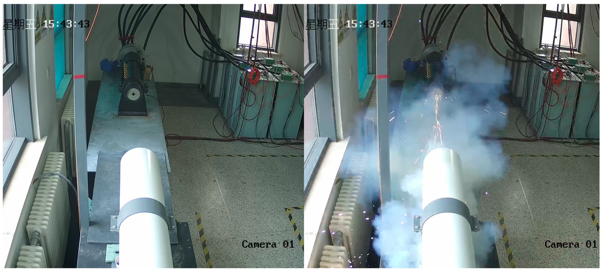
A physical view of the launcher test platform is shown in Figure 17.
Six PFN modules with a voltage of 5 kV were used as the excitation power source for the launcher. The peak current was measured to be 167 kA through the Rogowski Coil, and the measured armature discharge speed was 512 m/s, which met the expected requirements.
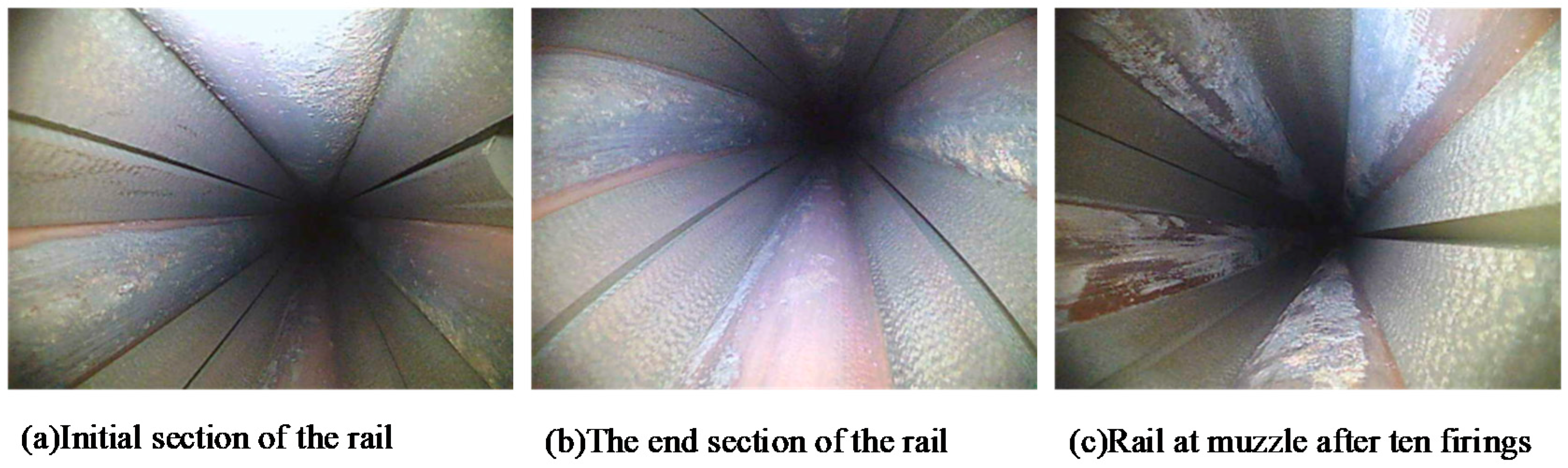
The rail damage after launch is shown in Figure 18. The armature model and the armature recovery after firing are shown in Figure 19. It can be seen that the initial section of the rail is relatively flat and no groove ablation can be observed, but a few planing pits are present. According to Marshall’s study [40], this indicates that the armature of the railgun has a reasonable interference design and ensures good stability of the armature’s motion. After one firing, no signs of turning were observed at the end of the rail, but aluminum fluid from the melted armature adhered to the rail surface. After ten firings, the adhesion of aluminum liquid at the end of the rail was more obvious and uneven, but still no turning was observed. According to Lin Q. H’s study [41], these phenomena indicate that the railgun works stably and with less damage under 160 kA current and can meet the operational requirements.
In Figure 19, it can be seen that the surface ablation of the armature after firing is light, and there is a slight melting at the tail end, resulting in solidified aluminum liquid on the armature arm surface. Overall, the armature can be considered to be in good condition after firing according to Watt [42].

6. Conclusions

In this paper, a hyperbolic augmented quadrupole railgun is designed, and the deformation resistance, contact characteristics and magnetic field characteristics of the railgun are investigated through the calculation of the moment of inertia and the FEM-BEM coupling simulation. The research results show that:
(1)
The deformation resistance of the rail is closely related to the shape of the rail section, and the deformation resistance of the convex rail is better than that of the concave and flat rail.
(2)
The contact force provided by the interference fit can keep the rail in good contact with the armature. The simulation results show that the contact force is more uniformly distributed after the convex rail and armature fit. In addition, the concave rail is able to restrain the armature motion more and make the armature work stably.
(3)
When the quadrupole railgun is energized, a cylindrical electromagnetic shielding area is formed in the bore, which enhances the electromagnetic compatibility of the railgun. After using the augmented rail, the electromagnetic shielding effect of the hyperbolic augmented quadrupole railgun is not diminished.
Based on the simulation results, a hyperbolic augmented quadrupole railgun was designed and launch tests were conducted. The experimental results show that the proposed railgun can ensure good contact and stable operation under a 167 kA current. Limited by the test conditions, we did not conduct continuous high-speed launch tests. In this case, residual stress and temperature rise may make the operating conditions of the railgun more severe. Furthermore, the proposed railgun uses conventional copper alloy materials, which are suitable under low-current conditions. However, to achieve higher currents and higher speeds, stronger materials and composite rails are what we need to consider in future research.

Author Contributions

Conceptualization, X.D.; Data curation, X.D.; Formal analysis, X.D.; Investigation, S.L.; Methodology, S.L.; Project administration, J.G.; Resources, J.G.; Software, X.D.; Supervision, S.L.; Validation, S.L.; Visualization, X.D.; Writing—original draft, X.D.; Writing—review and editing, S.L. All authors have read and agreed to the published version of the manuscript.

Funding

This research received no external funding.

Data Availability Statement

The data presented in this study are available on request from the corresponding author.

Acknowledgments

I thank my teachers, friends and other colleagues for their discussions on simulation and comments on this paper.

Conflicts of Interest

The authors declare no conflict of interest.

References

  1. Xin, F.; Zhang, D.; Yuan, W.; Ping, Y. Design and Analysis of the 270-kJ PPS for Augmented Railgun. IEEE Trans. Plasma Sci. 2017, 45, 1496–1502. [Google Scholar]
  2. Oliveirinha, J.; Gomes, A.S.; Cardoso, P.; Bizarro, P. Railgun: Streaming windows for mission critical systems. arXiv 2020, arXiv:2009.00361. [Google Scholar]
  3. Mcnab, I.R.; Stefani, F.; Crawford, M.; Erengil, M.; Persad, C.; Satapathy, S.; Vanicek, H.; Watt, T.; Dampier, C. Development of a naval railgun. In Proceedings of the IEEE Transactions on Magnetics, Snowbird, UT, USA, 25–28 May 2004; pp. 206–210. [Google Scholar]
  4. Overduin, J.; Pettaway, T.; Clark, H.; Edmonston, M. Rolling Railgun: A Lab Activity for Introductory Electromagnetism. Phys. Educ. 2020, 2, 2050017. [Google Scholar] [CrossRef]
  5. Zhang, B.; Kou, Y.; Jin, K.; Zheng, X. A multi-field coupling model for the magnetic-thermal-structural analysis in the electromagnetic rail launch. J. Magn. Magn. Mater. 2021, 519, 167495. [Google Scholar] [CrossRef]
  6. Zeng, D.; Lu, J.; Zheng, Y. Combined Fuzzy Time Series Prediction Method for Fault Prediction of EML Pulse Capacitors. IEEE Trans. Plasma Sci. 2021, 49, 905–913. [Google Scholar] [CrossRef]
  7. Yu, K.; Zhu, H.; Xie, X.; Duan, H.; Bao, Z. Loss Analysis of Air-Core Pulsed Alternator Driving an Ideal Electromagnetic Railgun. IEEE Trans. Transp. Electrif. 2021, 7, 1589–1599. [Google Scholar] [CrossRef]
  8. Abott, R. CNO Argues For Law of the Sea Treaty to Offset China, Calls Railgun Not Rapid Prototyping. Def. Dly. 2019, 3–5. Available online: https://www.defensedaily.com/cno-argues-law-sea-treaty-offset-china-calls-railgun-not-rapid-prototyping/navy-usmc/ (accessed on 1 September 2022).
  9. Aigner, S.; Igenbergs, E. Friction and ablation measurements in a round bore railgun. IEEE Trans. Magn. 1989, 25, 33–39. [Google Scholar] [CrossRef]
  10. Bai, Y.; Nardi, D.C.; Zhou, X.; Picón, R.A.; Flórez-López, J. A new comprehensive model of damage for flexural subassemblies prone to fatigue. Comput. Struct. 2021, 256, 106639. [Google Scholar] [CrossRef]
  11. Bandini, G.; Marracci, M.; Caposciutti, G.; Delmote, P.; Tellini, B. Current Distribution in Railgun Rails through Barycenter Filament Model. IEEE Trans. Instrum. Meas. 2021, 70, 6008808. [Google Scholar] [CrossRef]
  12. Qiang, Y.; He, Z.; Hao, L.; Yu, Y. Analysis of in-bore magnetic field in C-shaped armature railguns. Def. Technol. 2019, 15, 83–88. [Google Scholar]
  13. Lu, C.; Zhou, H.; Li, L.; Yang, A.; Xu, C.; Ou, Z.; Wang, J.; Wang, X.; Tian, F. Split-core magnetoelectric current sensor and wireless current measurement application. Measurement 2022, 188, 110527. [Google Scholar] [CrossRef]
  14. Gong, X.; Wang, L.; Mou, Y.; Wang, H.; Wei, X.; Zheng, W.; Yin, L. Improved Four-channel PBTDPA Control Strategy Using Force Feedback Bilateral Teleoperation System. Int. J. Control Autom. Syst. 2022, 20, 1002–1017. [Google Scholar] [CrossRef]
  15. Xie, H.; Yang, H.; Yu, J.; Gao, M.; Wang, H. Research progress on advanced rail materials for electromagnetic railgun technology. Def. Technol. 2021, 17, 11. [Google Scholar] [CrossRef]
  16. Yao, J.; Chen, L.; Xia, S.; He, J.; Li, C. The Effect of Current and Speed on Melt Erosion at Rail-Armature Contact in Railgun. IEEE Trans. Plasma Sci. 2019, 47, 2302–2308. [Google Scholar] [CrossRef]
  17. Gnegy-Davidson, C.G.; Wetz, D.A.; Wong, D. Impact of Corroded Copper Rails on the Performance of a Miniature Electromagnetic Launcher. Plasma Sci. IEEE Trans. 2017, 45, 1539–1544. [Google Scholar] [CrossRef]
  18. Chen, Y.; Weidong, X.U.; Yuan, W.; Zhao, Y.; Yan, P.; Lan, G. Sliding Electrical Contacts Between Aluminum Armature and Different Material Rails in Railgun. High Volt. Eng. 2013, 39, 937–942. [Google Scholar]
  19. Wen, Y.; Dai, L.; Lin, F. Effect of Geometric Parameters on Equivalent Load and Efficiency in Rectangular Bore Railgun. IEEE Trans. Plasma Sci. 2021, 49, 1428–1433. [Google Scholar] [CrossRef]
  20. Keshtkar, A.; Bayati, S. Effect of Rail’s Material on Railgun Inductance Gradient and Losses. In Proceedings of the Symposium on Electromagnetic Launch Technology, Victoria, BC, Canada, 10–13 June 2008. [Google Scholar]
  21. Yin, Q.; Zhang, H.; Li, H.J. Analysis of In-bore Magnetic and Electric Fields in Electromagnetic Railgun under Dynamic Condition. Acta Armamentarii 2017, 38, 1059–1066. [Google Scholar]
  22. Du, X.; Liu, S.; Guan, J. Calculation Method of Projectile Movement Characteristics for Complex Structure Railgun. Wirel. Commun. Mob. Comput. 2022, 2022, 8966115. [Google Scholar] [CrossRef]
  23. Zhou, P.; Li, B. Exergy Analysis of the Electromagnetic Railgun. IEEE Trans. Plasma Sci. 2021, 49, 3980–3987. [Google Scholar] [CrossRef]
  24. Hsieh, K.T.; Satapathy, S.; Hsieh, M.T. Effects of Pressure-Dependent Contact Resistivity on Contact Interfacial Conditions. IEEE Trans. Magn. 2008, 45, 313–318. [Google Scholar] [CrossRef]
  25. Liu, S.; Miao, H.; Li, M. Investigation of the Armature Contact Efficiency in a Railgun. IEEE Trans. Plasma Sci. 2019, 47, 3315–3319. [Google Scholar] [CrossRef]
  26. Yang, Y.; Dai, K.; Yin, Q.; Liu, P.; Zhang, H. In-Bore Dynamic Measurement and Mechanism Analysis of Multi-Physics Environment for Electromagnetic Railguns. IEEE Access 2021, 9, 16999–17010. [Google Scholar] [CrossRef]
  27. Kim, B.K.; Hsieh, K.T. Effect of rail/armature geometry on current density distribution and inductance gradient. IEEE Trans. Magn. 1999, 35, 413–416. [Google Scholar] [CrossRef]
  28. Li, T.; Feng, G.; Liu, S. Analysis of electromagnetic characteristics of the proposed composite four-rail electromagnetic launcher. Sci. Eng. Compos. Mater. 2022, 29, 113–125. [Google Scholar]
  29. Li, S.; Lu, J.; Cheng, L.; Zeng, D. A high precision in-bore velocity measurement system of railgun based on improved Bi-LSTM network. Measurement 2020, 169, 108501. [Google Scholar] [CrossRef]
  30. Chaudhuri, D.; Dalvi, S.; Khatri, M.; Chatterjee, S.; Bhuvaneswari, G. Design of Gate Drive Circuit for Thyristor Stack in Electromagnetic Railgun by Load-Line Analysis. IEEE Trans. Plasma Sci. 2020, 49, 383–388. [Google Scholar] [CrossRef]
  31. Chen, J.W.; Qing-Ao, L.V.; Xing, Y.C.; Chuan-Tong, D.U.; Zhang, Q. Preparation process and launching test of armature coated with Sn alloy for electromagnetic railgun. J. Magn. Mater. Devices 2019, 50, 5. [Google Scholar]
  32. Heydari, M.B.; Asgari, M.; Keshtkar, A. A Novel Structure of Augmented Railgun Using Multilayer Magnets and Sabots. IEEE Trans. Plasma Sci. 2019, 47, 3320–3326. [Google Scholar] [CrossRef]
  33. Liu, Y.; Guo, W.; Zhang, T.; Zhang, H.; Su, Z. Structural Design of Armature with Interference at Both Ends and Analysis of Its Launching Performance. IEEE Trans. Plasma Sci. 2020, 48, 2922–2931. [Google Scholar] [CrossRef]
  34. Coffo, M.; Gallant, J. Modelling of a Parallel Augmented Railgun with Pspice Validation of the Model and Optimization of the Augmenting Circuit. In Proceedings of the 2007 16th IEEE International Pulsed Power Conference, Albuquerque, NM, USA, 22 June 2007–17 June 2008. [Google Scholar]
  35. Liu, Y.; Huang, K.; Zhang, T.; Fan, W.; Guo, W. Some Key Parameters for Revolving Armature-Type Railgun. IEEE Trans. Plasma Sci. 2020, 48, 1316–1322. [Google Scholar] [CrossRef]
  36. Miao, H.; Liu, S.; Liu, M.; Yang, Z. Simulation and Analysis of Electromagnetic Propulsion for Series-Connected Augmented Quadrupole Railgun. J. Air Force Eng. Univ. (Nat. Sci. Ed.) 2018, 19, 3. [Google Scholar]
  37. Parker, J.V. Why plasma armature railguns don’t work (and what can be done about it). IEEE Trans. Magn. 2002, 25, 418–424. [Google Scholar] [CrossRef]
  38. Cooper, K.P.; Jones, H.N.; Meger, R.A. Analysis of Railgun Barrel Material. IEEE Trans. Magn. 2006, 43, 120–125. [Google Scholar] [CrossRef]
  39. Kerrisk, J. Electrical and thermal modeling of railguns. IEEE Trans. Magn. 1984, 20, 399–402. [Google Scholar] [CrossRef]
  40. Marshall, R.A. Railgunnery: Where have we been? Where are we going? IEEE Trans. Magn. 2001, 37, 440–444. [Google Scholar] [CrossRef]
  41. Lin, Q.-H.; Li, B.-M. Numerical simulation of dynamic large deformation and fracture damage for solid armature in electromagnetic railgun. Def. Technol. 2020, 16, 78–83. [Google Scholar] [CrossRef]
  42. Zielinski, A.; Watt, T.; Motes, D. Disrupting Armature Ejecta and Its Effects on Rail Damage in Solid-Armature Railguns. IEEE Trans. Plasma Sci. 2011, 39, 941–946. [Google Scholar] [CrossRef]
Figure 1. Model of electromagnetic launcher. (a) Current direction of the railgun. (b) Structure of the armature. (c) Structure of the augmented railgun.
Electronics 11 03108 g001
Figure 2. Coupling relationship of the model.
Electronics 11 03108 g002
Figure 3. Three matching forms of armature and rails. (a) Schematic of the circuit connection. (b) Schematic of the structure and size of the railgun.
Electronics 11 03108 g003
Figure 4. Rails’ coordinate system and dimensions. (a) Flat rail; (b) convex rail, (c) concave rail.
Electronics 11 03108 g004
Figure 5. Inertia moment of rails with different parameters. (a) Varies vs. m. (b) Varies vs. α.
Electronics 11 03108 g005
Figure 6. Deformation of three different rails.
Electronics 11 03108 g006
Figure 7. Von mises Stress distribution on the rails.
Electronics 11 03108 g007
Figure 8. Contact pressure distribution.
Electronics 11 03108 g008
Figure 9. Total contact force vs. time. (a) Current used in simulation and test; (b) Contact force.
Electronics 11 03108 g009
Figure 10. Distribution of contact force at different time.
Electronics 11 03108 g010
Figure 11. Contact parameters of the three types of rail.
Electronics 11 03108 g011
Figure 12. Magnetic field distribution at different positions in the bore of a traditional railgun.
Electronics 11 03108 g012
Figure 13. The distribution of the magnetic field in the center of the railgun bore.
Electronics 11 03108 g013
Figure 14. Magnetic field distribution in the bore of the augmented quadrupole railgun. (a) Magnetic field in x and y directions on section a; (b) Magnetic field in x and y directions on section b. (c) Magnetic field in x and y directions on section c; (d) Total magnetic field norm on section a. (e) Schematic diagram of the rail gun and section location.
Electronics 11 03108 g014
Figure 15. Thrust of augmented quadrupole railgun and non-augmented quadrupole.
Electronics 11 03108 g015
Figure 16. Schematic diagram of the test platform.
Electronics 11 03108 g016
Figure 17. Electromagnetic railgun test platform.
Electronics 11 03108 g017
Figure 18. Rail after launch. (a) Initial section of the rail (armature displacement less than 50 mm). (b) The end section of the rail (the distance to the muzzle is less than 50 mm). (c) Rail at the muzzle after ten firings (the distance to the muzzle is less than 50 mm).
Electronics 11 03108 g018
Figure 19. Armature recovered after launch.
Electronics 11 03108 g019
Table 1. Statistical results of initial contact parameters.
Type of Rail F c o n   [ N ] P max   [ Pa ] S D C A   [ % ] E C A   [ % ]
Type1 8.48 × 10 3 5.95 × 10 7 47.4644.48.4
Type2 8.06 × 10 3 4.98 × 10 7 52.1945.711.4
Type3 1.71 × 10 4 9.43 × 10 7 93.9719.115.1
Publisher’s Note: MDPI stays neutral with regard to jurisdictional claims in published maps and institutional affiliations.

