Article

Novel Voltage-Based Weighted Hybrid Force/Position Control for Redundant Robot Manipulators

1
School of Mechanical and Electrical Engineering, Central South University, Changsha 410083, China
2
The State Key Laboratory of High Performance Complex Manufacturing, Central South University, Changsha 410083, China
*
Author to whom correspondence should be addressed.
Electronics 2022, 11(2), 179; https://doi.org/10.3390/electronics11020179
Submission received: 30 November 2021 / Revised: 3 January 2022 / Accepted: 5 January 2022 / Published: 7 January 2022
(This article belongs to the Section Systems & Control Engineering)

Abstract

:
Existing hybrid force/position control algorithms mostly explicitly contain a dynamic model. Moreover, force and position controllers will be switched frequently. To solve the above problems, a novel voltage-based weighted hybrid force/position control algorithm is proposed for redundant robot manipulators. Firstly, mapping between voltage and terminal position and orientation is established so that the designed controller can be simplified by adopting the motor current as the feedback to replace the tedious calculation of the dynamic model. Secondly, a voltage-based weighted hybrid force/position control algorithm is proposed to eliminate the selection matrix. Force and position control laws are summed directly through a weighted way to avoid the problems of space decomposition and switching. Thirdly, the stability is proven using Lyapunov stability theory, then the selection method for weighted coefficient is provided. Fourthly, comparative simulations are performed. Results show that the proposed algorithm is suitable for impedance control and hybrid force/position control and can compensate for their deficiencies. Lastly, the transport experiment in the YZ plane is conducted. Results show that position and force accuracies in the Y- and Z-axis directions are 3.489 × 10⁻⁴ and 7.313 × 10⁻⁴ m and 1.238 × 10⁻¹ and 1.997 × 10⁻¹ N, respectively. Accordingly, it can effectively improve the operation capability and control accuracy.

1. Introduction

With the development of intelligent manufacturing, robot manipulators [1,2,3,4] have been widely used in various industry fields, such as spraying [5], welding [6], transport [7], and assembly [8]. Traditional nonredundant robot manipulators could not complete a precise operation with high flexibility requirements due to their freedom limitation. Singular position and joint limit are easily encountered in the operation process [9,10,11]. Therefore, redundant robot manipulators are designed to overcome the above defects. The Jacobian matrix of redundant robot manipulators could not be derived directly due to their redundant degree of freedom (DOF). Building their dynamic model is more difficult due to their strong coupling. Thus, the abovementioned problems should be solved during the control of redundant robot manipulators.
With increasing complexity of tasks, the position control of redundant robot manipulators could not meet requirements. As a result, the force control of redundant robot manipulators has become the focus of attention. Force control algorithms of redundant robot manipulators can be divided into impedance control and hybrid force/position control. The aim of impedance control is to prevent the contact force exceeding the set threshold by controlling the contact state between the robot manipulator and the environment. It can reduce the impact when the robot manipulator is in contact with the environment. Its control effect depends on the accuracy of the impedance model [12,13]. Initial parameters of the impedance model can be obtained by solving the minimization problem of the performance criterion and the critical damping condition of the robot–environment interaction system [14]. Uncertainties of the above problem can be considered by the optimization methods, such as robust optimization [15] or stochastic optimization [16]. Then, the parameters can be adjusted online by using intelligent algorithms, such as neural network [14] or adaptive control [17], in practical applications. Consequently, the calculation of impedance control is considerably tedious, and its real-time performance is poor. The control law also contains acceleration feedback. It is difficult to measure directly and is thus obtained generally through differential calculation or adding an observer. However, the differential operation is prone to generate noise, and adding an observer would make the controller structure more complex than before [18].
The hybrid force/position control can be suitable for compliant control. It can enable the robot manipulator to maintain certain terminal force for machining the workpiece. Hence, the hybrid force/position control is universal. Komada et al. [19] proposed a hybrid force/position control algorithm for redundant robot manipulators. A disturbance observer was designed to eliminate the inverse dynamics. Navvabi et al. [20] designed an extended adaptive fuzzy sliding mode controller in the presence of state-dependent uncertainties for a Stewart Manipulator. Modified extended Kalman filter was adopted to estimate contact parameters. Li et al. [21] proposed a position/force same loop control algorithm based on genetic neural network (GNNPFSLC) for the compliance control of a hydraulic heavy-duty manipulator. A multibody dynamic model was established, and the genetic neural network algorithm was adopted to optimize the traditional hybrid force/position control. Kumar et al. [22] proposed a novel hybrid force/position control algorithm for time-varying constrained reconfigurable manipulators. Radial basis function neural network was adopted to estimate the unknown dynamics. An adaptive compensator was designed to overcome the aftereffects of the friction terms and neural network reconstruction error. The hybrid force/position control algorithm directly controls the force error; therefore, its controller structure is simpler than that of the impedance control, and the terminal force can track the changes in the desired force more accurately [13].
A dynamic model of a redundant robot manipulator is more complex than that of a nonredundant robot manipulator, and the controller structure of its hybrid force/position control algorithm is also more complex. This condition leads to tedious calculation and poor real-time performance in practical applications. To solve the above control problem caused by dynamic model, many experts and scholars have conducted extensive research on the model-free control algorithm [23,24,25,26]. This algorithm only needs input and output information and does not depend on the system dynamic model; its characteristics are simple calculation, strong adaptability, and wide application range [23,24,25,26]. Relevant information required for control is obtained via online identification and estimation of the dynamic model. Consequently, its control period is longer than that of the general model-based control algorithm, and its real-time performance is poorer [27,28]. A new control algorithm that has the advantages of model-free and model-based control should be established. Fateh [29] proposed a voltage-based control algorithm. The motor voltage was regarded as the control input, and the motor current term representing all dynamic factors of a robot manipulator in the motor dynamics was cancelled by feedback linearization. As a result, the control law was simplified, and it is free of any robot manipulator dynamics. Fateh et al. [30] proposed a voltage-based adaptive impedance control algorithm. The impedance control was combined with a voltage control strategy. A gradient descent algorithm was adopted to regulate the impedance parameters adaptively and solve the parameter selection problem of the impedance model. Veysi et al. [31] proposed a voltage-based adaptive fuzzy sliding mode control algorithm. Voltage-based sliding mode control was adopted to overcome the uncertainties in the dynamic model, and it was combined with adaptive fuzzy control to overcome the chattering phenomenon of sliding mode control and reduce the number of sensors required for control. Zaare et al. [32] proposed a voltage-based sliding mode control algorithm for an n-DOF flexible joint robot manipulator. The system dynamic model was decomposed into n independent subsystems, and three layers of sliding mode surfaces were designed for each subsystem. This condition could effectively overcome the uncertainties in the dynamic model. The voltage-based control algorithm explicitly included motor dynamics and implicitly included robot manipulator dynamics. The motor current term in the control law could represent all dynamic factors of the robot manipulator; hence, the algorithm complexity could be reduced, and high-accuracy control could be guaranteed [29,30]. Nevertheless, the voltage-based control algorithm was only applicable to the impedance control of nonredundant robot manipulators, and it could not be directly applied to the hybrid force/position control of redundant robot manipulators.
The control effect of a hybrid force/position control algorithm depends on the accurate decomposition of task space and the correct switching on the basis of the selection matrix. Chattering easily occurs during the transformation from unconstrained motion to constrained motion [33,34,35]. In the case that a robot manipulator performs a simple operation on a smooth surface, the position and force subspaces can be accurately decomposed due to clear environmental constraints, then the hybrid force/position control algorithm can achieve a good control effect. In the case that a robot manipulator performs a complex operation on an uneven surface, the position and force subspaces cannot be accurately decomposed due to time-varying environmental constraints; consequently, the hybrid force/position control algorithm is inapplicable [36]. In the case that a robot manipulator transports a workpiece or the workpiece moves freely before contacting with the environment during other operations, the robot manipulator should provide not only the force required for the motion of the workpiece but also stable clamping force to maintain the workpiece. When the motion direction of the workpiece is the same as its clamping force direction, if this direction is regarded as a force subspace for the hybrid force/position control algorithm, then its position accuracy cannot be guaranteed. On the contrary, if this direction is regarded as a position subspace, then its force position cannot be guaranteed [13]. Therefore, a novel voltage-based weighted hybrid force/position control algorithm (VBWHFPC) is proposed for redundant robot manipulators to realize dynamic force planning during operations. To simplify the controller, the voltage-based control algorithm is adopted, and it is improved on the basis of the characteristics of redundant robot manipulators. The improved algorithm is then applied to the hybrid force/position control of redundant robot manipulators. To overcome the problems of space decomposition and switching, the selection matrix is eliminated, and the force and position control laws are summed directly through a weighted way. This condition can guarantee the position and force accuracies at the same time in the force direction.
The main contributions of this paper are highlighted below.
(1)
Mapping between the voltage of the joint motor and the terminal position and orientation of a redundant robot manipulator is established. The voltage-based control algorithm is improved on the basis of the above relationship, then it is combined with the hybrid force/position control algorithm. Accordingly, voltage-based hybrid force/position control can be realized for the redundant robot manipulator. It can simplify the force and position controllers at the same time and improve their control efficiency and response speed.
(2)
To avoid the problems of space decomposition and switching in the traditional hybrid force/position control, the force and position control laws are summed directly through a weighted way, and the selection matrix is eliminated. Then, voltage-based weighted hybrid force/position control can be realized for the redundant robot manipulator. On the premise of ensuring stability, a method for selecting the weighting coefficient is provided.
(3)
The proposed novel control algorithm overcomes the defects of impedance control and hybrid force/position control. Moreover, the controller can be simplified by adopting the motor current as the feedback to replace the tedious calculation of the dynamic model of the redundant robot manipulator. Therefore, the proposed algorithm is a general control method. It is suitable for hybrid force/position control and impedance control. It can also greatly simplify the controller design.
The rest of this paper is organized as follows. A dynamic model of a redundant robot manipulator system and mapping between the voltage of the joint motor and the terminal position and orientation of the redundant robot manipulator are established in Section 2. A voltage-based weighted hybrid force/position controller is designed for the redundant robot manipulator. Its stability is proven, and a method for selecting the weighting coefficient is provided in Section 3. Comparative simulations are conducted, and their results are analyzed in Section 4. A transport experiment is carried out in Section 5. Conclusions are indicated in Section 6.

2. Voltage-Based Dynamic Model for a Redundant Robot Manipulator

2.1. Dynamic Model of a Redundant Robot Manipulator

For an actual redundant robot manipulator system, the model structure should include not only the dynamic model of the redundant robot manipulator, but also the dynamic model of the actuator and transmission mechanism. Therefore, a system model considering the dynamics of the redundant robot manipulator and motors is established. It is assumed that the redundant robot manipulator is driven by permanent magnet brush direct current motor [29,30].
The motor voltage balance equation [29,30] of the redundant robot manipulator system is
v = R i + L d i d t + k b d θ m d t
where v is the armature voltage matrix, R is the armature resistance matrix, i is the armature current matrix, L is the armature inductance matrix, k b is the back electromotive force constant matrix, and θ m is the motor angle matrix.
The relationship between the joint torque of the redundant robot manipulator and the motor current can be obtained on the basis of the motor torque balance equation [29,30,37] and the relationship [29,30] between the motor torque and the motor current, as shown as follows:
T m = J m θ ¨ m + B m θ ˙ m + r T j + T f m = k m i
where T m is the motor torque matrix, J m is the sum matrix of the actuator and gear inertia, θ ¨ m is the motor angular acceleration matrix, B m is the damping coefficient matrix, θ ˙ m is the motor angular velocity matrix, r is the gear reduction ratio matrix, T j is the joint torque matrix of the redundant robot manipulator considering only the friction torque of joints, T f m is the friction torque matrix of motors, and k m is the motor torque constant matrix.
In consideration of friction and external disturbance of joints, the dynamic equation of the redundant robot manipulator with n (n > 6) DOF is shown below.
T j = M ( q ) q ¨ + C ( q , q ˙ ) q ˙ + G ( q ) + T f j + D + T t
where q ¨ is the joint angular acceleration matrix of the redundant robot manipulator, q ˙ is the joint angular velocity matrix of the redundant robot manipulator, q is the joint angle matrix of the redundant robot manipulator, M ( q ) is the inertia matrix, C ( q , q ˙ ) is the centrifugal and Coriolis torque matrix, G ( q ) is the gravitational torque matrix, T f j is the friction torque matrix of joints, D is the external disturbance matrix, and T t is the equivalent joint torque matrix of the redundant robot manipulator that corresponds to the generalized terminal force.
Substituting (3) into (2), yields:
k m i = J m θ ¨ m + B m θ ˙ m + r [ M ( q ) q ¨ + C ( q , q ˙ ) q ˙ + G ( q ) + T f j + D + T t + r 1 T f m ]
Then, the friction torque of motors T f m and the friction torque of joints T f j can be merged into a resultant friction torque T f , as described below:
T f = T f j + r 1 T f m
where T f is the resultant friction torque matrix of motors and joints.
Therefore, the dynamic equation of the redundant robot manipulator considering both the friction torque of motors and the friction torque of joints is described below:
T = M ( q ) q ¨ + C ( q , q ˙ ) q ˙ + G ( q ) + T f + D + T t
where T is the joint torque matrix of the redundant robot manipulator considering both the friction torque of motors and the friction torque of joints.
Equation (2) can also be expressed as:
k m i = J m θ ¨ m + B m θ ˙ m + r T
In accordance with the virtual work principle [38,39], the virtual work generated using the virtual displacement of the joint space is equal to the virtual work generated using the virtual displacement of the task space. Vectors δ q and δ X depend on each other. The relationship between them satisfies the geometric constraint specified by the Jacobian matrix. The relationship is shown as follows:
T t T δ q = F t T δ X = F t T J δ q
where F t = [ f x f y f z τ x τ y τ z ] T , J = [ J 1 J i J n ] , i = 1 n , and J i = [ z i × n i p 0 z i ] = [ z i × ( R i 0 p n i ) z i ] . T t T is the transpose of the equivalent joint torque matrix T t ; δ q is the virtual displacement of the redundant robot manipulator in the joint space; F t is the generalized terminal force vector; F t T is the transpose of the generalized terminal force vector F t ; δ X is the virtual displacement of the redundant robot manipulator in the task space; f x , f y , and f z are the terminal force in the x, y, and z axes of the base frame {0}, respectively; τ x , τ y , and τ z are the terminal torque in the x, y, and z axes of the base frame {0}, respectively; J is the Jacobian matrix; J i is the ith column of the Jacobian matrix; z i is the coordinate vector in the base frame {0} corresponding to the z-axis unit vector of frame { i }; n i p 0 is the position vector in the base frame {0} that expresses the position of frame { n } with respect to frame { i }; R i 0 is the rotation matrix between frame { i } and base frame {0}; p n i is the position vector of frame { n } with respect to frame { i }; and n is the number of DOFs for the redundant robot manipulator.
The relationship between the equivalent joint torque matrix T t and the generalized terminal force vector F t can be obtained by simplifying (8), as shown as follows:
T t = J T F t
where J T is the transpose of the Jacobian matrix J , also known as the force Jacobian.
In the redundant robot manipulator system, each joint is driven by a motor and connected with the motor by a reducer; the relationship [29,30] between the joint and motor angles is shown as follows:
q = r θ m
To realize voltage-based control of the redundant robot manipulator, the control input should be the motor armature voltage v . The state vector is Z = [ Z 1 Z 2 Z 3 ] T , where Z 1 = q , Z 2 = q ˙ , and Z 3 = i . The state-space equation of the redundant robot manipulator system can be obtained on the basis of (1)–(10), as shown as follows:
[ Z ˙ 1 Z ˙ 2 Z ˙ 3 ] = [ O n × n I n × n O n × n O n × n a b a k m O n × n L 1 k b r 1 L 1 R ] [ Z 1 Z 2 Z 3 ] + [ O n × n O n × n L 1 ] v + [ O n × 1 a c O n × 1 ]
where a = [ J m r 1 + r M ( q ) ] 1 , b = B m r 1 + r C ( q , q ˙ ) , and c = r [ G ( q ) + T f + D + J T F t ] .
The hybrid force/position control of the redundant robot manipulator is to control the end-effector or the workpiece held by the end-effector; hence, its control objects are the terminal position, orientation, and generalized force. The voltage-based control algorithm is combined with the hybrid force/position control algorithm to simplify the controller by adopting the motor current as the feedback to replace the tedious calculation of the dynamic model of the redundant robot manipulator. The control input of the proposed algorithm is the voltage of the joint motor, and among the control outputs are the terminal position and orientation. Mapping between the voltage of the joint motor and the terminal position and orientation of the redundant robot manipulator should be established to make the design process of the controller intuitive and simple.

2.2. Mapping between Voltage and the Terminal Position and Orientation

The relationship between the terminal velocity of the redundant robot manipulator and its joint angular velocity is shown below:
q ˙ = J + X ˙ + ( I n × n J + J ) ε
where X ˙ is the terminal velocity matrix of the redundant robot manipulator, J + is the pseudo-inverse of the Jacobian matrix J , and ε is an arbitrary vector in the null space of the Jacobian matrix J .
Equation (1) represents the mapping between the motor voltage and the motor angle in the motor space. The mapping between the motor voltage and the terminal position and orientation of the redundant robot manipulator can be obtained by converting (1) from the motor space to the task space on the basis of (10) and (12), as shown as follows:
v = R i + L d i d t + k b r 1 J + X ˙ + k b r 1 ( I n × n J + J ) ε
where r 1 is the inverse of the gear reduction ratio matrix r .
The second item on the right side of (12) represents the joint self-motion of the redundant robot manipulator. Its value does not affect the terminal motion of the redundant robot manipulator; thus, the optimal inverse solution of joint angular velocity can be selected by adjusting this item. The most common solution method is the gradient projection method [40]. Vector ε can be represented as a product of the gradient H ( q ) of the performance optimization function and the amplification factor matrix k a , that is,
ε = k a H ( q )
where H ( q ) is the gradient of the performance optimization function, and k a is the amplification factor matrix.
For solving the inverse kinematics of the redundant robot manipulator, the advantage of the gradient projection method is that an appropriate performance optimization function H ( q ) can be selected to obtain a set of optimal solutions that meet the requirements. In accordance with the operation requirements and structural characteristics of the redundant robot manipulator, the joint limit avoidance [41] and the singularity avoidance [42] are generally regarded as the optimization objectives. Therefore, the performance optimization function can be expressed as shown below:
H ( q ) = H 1 ( q ) + H 2 ( q ) H 1 ( q ) = 1 n i = 1 n ( q i q i , m i d q i , m i d q i , m a x ) 2 H 2 ( q ) = d e t ( J J T )
where q i , m i d = q i , m i n + q i , m a x 2 , H ( q ) is the total performance optimization function, H 1 ( q ) is the performance optimization function whose optimization objective is the joint limit avoidance, H 2 ( q ) is the performance optimization function whose optimization objective is the singularity avoidance, q i is the ith joint angle of the redundant robot manipulator, q i , m i n is the lower bound of the allowable range for the ith joint angle of the redundant robot manipulator, q i , m a x is the upper bound of the allowable range for the ith joint angle of the redundant robot manipulator, q i , m i d is the middle value of the allowable range for the ith joint angle of the redundant robot manipulator, and det represents the calculation of matrix determinant.
The performance optimization function H 1 ( q ) can choose a set of joint angles that approach the middle value of the allowable range to avoid the situation in which the redundant robot manipulator moves to the joint limit position. The performance optimization function H 2 ( q ) represents the operability of the redundant robot manipulator and the proximity between the current position and orientation and the singular position and orientation. Compared with the kinematic characteristics of nonredundant robot manipulators, those of redundant robot manipulators are more complex. Their Jacobian matrix cannot be directly inverted. The pseudo-inverse of the Jacobian matrix should be calculated, then infinite solutions of the inverse kinematics would be available, as shown in (12) and (13). Therefore, the controller structure of the redundant robot manipulator is more complex. In the case that vector ε is a zero vector and J + is replaced with J 1 , Equations (12) and (13) can be converted into a form suitable for the nonredundant robot manipulator. Consequently, the relevant characteristics of the redundant robot manipulator are more general. Equation (13) indicates that the dynamic model of the redundant robot manipulator is not explicitly expressed in the mapping between the voltage v of the joint motor and the terminal position and orientation X of the redundant robot manipulator. The motor current i is adopted as the feedback to replace the tedious calculation of the dynamic model of the redundant robot manipulator. From (2), the motor current i contains all the force and torque factors required for the operation of the redundant robot manipulator. Therefore, Equation (13) can accordingly be applied to the force and position control of the redundant robot manipulator, and it can simplify the controller without affecting its dynamic performance.

3. Weighted Hybrid Force/Position Control of a Redundant Robot Manipulator

3.1. VBWHFPC

The traditional hybrid force/position control algorithm generally explicitly contains a dynamic model of a robot manipulator, but an accurate dynamic model is generally difficult to obtain. As a result, the control accuracy is difficult to guarantee. The control law is also complex and tedious, which can result in the reduction of implementation efficiency. To design a controller without a dynamic model of a robot manipulator and simplify the control law, the control system of the redundant robot manipulator adopts a voltage-based hybrid force/position control strategy.
Equation (2) presents that the driving effect of the joint torque of the redundant robot manipulator is included in the motor current. Given the motor current is included in the control law, the dynamic model of the redundant robot manipulator needs not be considered. Then, the position control law for each joint of the redundant robot manipulator can be designed by referring to (13), as shown below:
u = R i + L d i d t + k b r 1 J + [ X ˙ d + k p p ( X d X ) ] + k b r 1 ( I n × n J + J ) ε
where u = [ u 1 u j u n ] T , j = 1 n , u is the total control input matrix of the redundant robot manipulator system, u i is the control input of each joint of the redundant robot manipulator, X ˙ d is the desired terminal velocity matrix of the redundant robot manipulator, k p p is the proportional coefficient matrix of position control, X d is the desired terminal position and orientation matrix of the redundant robot manipulator, and X is the actual terminal position and orientation matrix of the redundant robot manipulator.
The voltage-based control algorithm is combined with the hybrid force/position control of the redundant robot manipulator. Then, the hybrid force/position control law of the redundant robot manipulator can be designed by referring to (16), as shown below:
u = R i + L d i d t + k b r 1 J + [ X ˙ d + S k p p ( X d X ) + S ¯ k f p ( F t d F t ) ] + k b r 1 ( I n × n J + J ) ε
where S ¯ = I 6 × 6 S , k f p is the proportional coefficient matrix of force control, F t d is the desired generalized terminal force vector, and S , S ¯ are selection matrices. They are diagonal matrices whose elements on the main diagonal can only be 0 or 1.
For the hybrid force/position control algorithm with the selection matrix, the task space of the redundant robot manipulator should be decomposed into the position and force subspaces on the basis of environmental constraints. If environmental constraints are difficult to ensure or change in real time, the accurate space decomposition cannot be completed. The hybrid force/position control algorithm with the selection matrix is difficult to adopt in this case. The strict space decomposition would also lead to the fact that force control cannot be implemented in the position subspace, and position control cannot be implemented in the force subspace. Therefore, the hybrid force/position control algorithm with the selection matrix is no longer applicable to operations that require high accuracy in force and position in a certain direction.
To prevent the problems of space decomposition and switching and meet the accuracy requirements of force and position simultaneously in all directions, a control strategy of the redundant robot manipulator is designed by weighted summing the force and position control laws, as shown in (18). Its control block diagram is shown in Figure 1.
u = R i + L d i d t + k b r 1 J + [ X ˙ d + k p ( X d X ) + k f ( F t d F t ) ] + k b r 1 ( I n × n J + J ) ε
where k p is the weighted coefficient matrix of position control, k f is the weighted coefficient matrix of force control.
For some redundant robot manipulators, their systems cannot directly obtain the actual value of motor current. In this case, the motor current i can be calculated by the joint torque T, the joint angular acceleration q ¨ and the joint angular velocity q ˙ of the redundant robot manipulator on the basis of (7) and (10). The time derivative of motor current d i d t can be obtained by two methods in [43]. The first method is to design a measuring device in which the voltage across the coil is proportional with the time derivative of current. The second method is to add a filter to the controller to calculate the soft time derivative of current. The transfer function of the filter is s α s + 1 . Here, α = 0.001 can meet the requirements. The input of the filter is the motor current i and its output is the time derivative of motor current d i d t .
The Jacobian matrix J contained in the designed control strategy (18) represents the mapping between the terminal and joint angular velocities. Its transpose J T is known as the force Jacobian matrix and represents the mapping between the equivalent joint torque T t and the generalized terminal force F t . Nonetheless, the expression of J in (8) and the derivation process of (9) indicate that J and J T are related only to the kinematic parameters of the redundant robot manipulator and not to its dynamic parameters. Hence, the dynamic model of the redundant robot manipulator is not explicitly expressed in the designed control strategy (18). It can effectively simplify the controller and improve the control efficiency.

3.2. Selection of Weighting Coefficients and Stability Analysis

Appropriate weighted coefficients k p and k f should be selected to guarantee the implementation of the proposed control algorithm and achieve a good control effect. The proposed control algorithm must first satisfy the stability conditions to ensure the stability and convergence of the control process. Therefore, the stability of the proposed algorithm should firstly be proven using Lyapunov stability theory. The satisfied constraint conditions of the weighting coefficient should then be determined.
The generalized terminal force model should be established to prove the stability of the proposed control algorithm. This generalized terminal force model is only used for stability proof, and it is not included in the actual control algorithm.
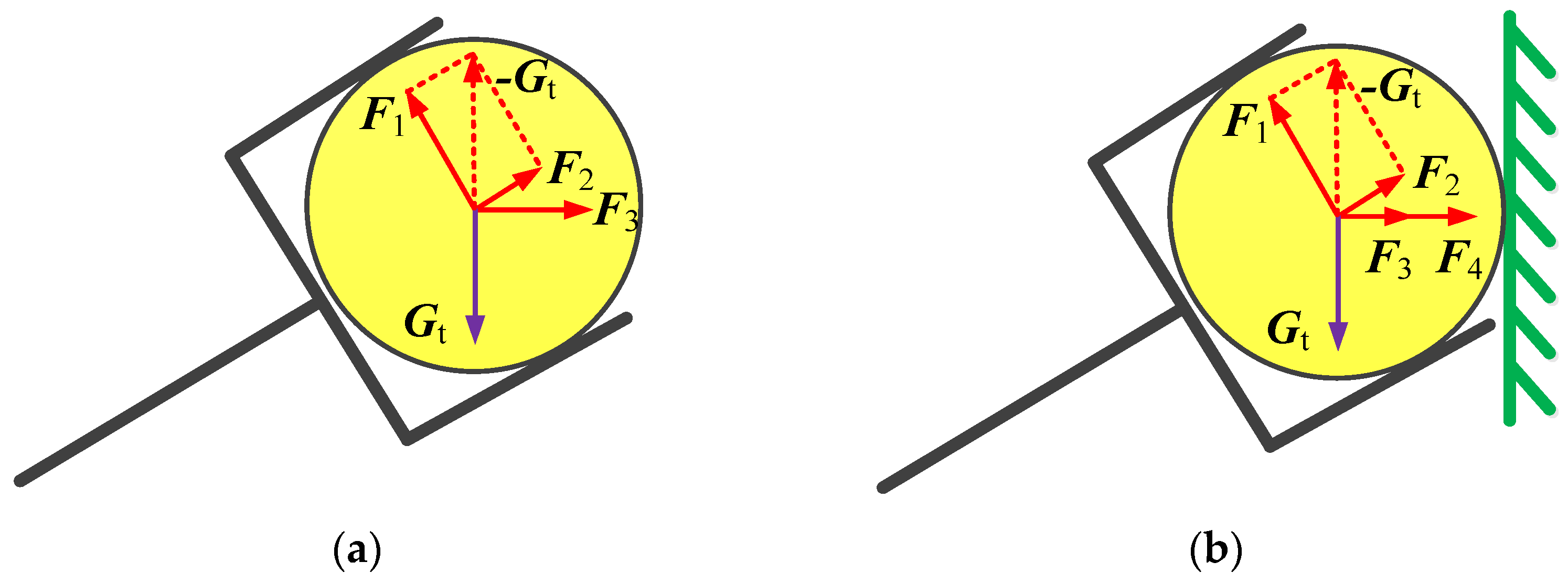
In the case that the workpiece is in free motion, that is, the workpiece is not in contact with the environment, the generalized terminal force contains the supporting force F 1 in the normal direction of the workpiece surface, the friction force F 2 that prevents the workpiece from slipping in the tangent direction of the workpiece surface, and the driving force F 3 that drives the motion of the workpiece, as shown in Figure 2a. The resultant force of F 1 and F 2 is the clamping force required to maintain the stability of the workpiece. Compared with the gravity G t of the workpiece, their magnitudes are the same, but their directions are opposite. That is, F 1 + F 2 = G t . F 3 is proportional to the acceleration of the workpiece. That is, F 3 = M t X ¨ . Therefore, the generalized terminal force that is the resultant force of F 1 , F 2 , and F 3 can be described below:
F t = M t X ¨ G t
where M t is the inertia matrix of the workpiece that is determined by the mass and the moment of inertia, and G t is the gravity vector of the workpiece.
In the case that the workpiece is in contact with the environment, the generalized terminal force contains the supporting force F 1 , the friction force F 2 , the driving force F 3 , and the balance force F 4 that offsets the environmental reaction force, as shown in Figure 2b. The velocity of the redundant robot manipulator generally changes slowly to guarantee the safety of the workpiece and the environment. That is, its acceleration is small; hence, the driving force F 3 can be ignored. The environmental model can be approximately expressed as the spring damping system [18,41]. That is, F 4 = B e X ˙ + K e ( X X b ) . The parameter matrices B e and K e can be obtained by offline identification and online estimation [41]. Therefore, the generalized terminal force that is the resultant force of F 1 , F 2 , F 3 , and F 4 can be described below:
F t = B e X ˙ + K e ( X X b ) G t
where B e is the damping matrix of the environment, K e is the stiffness matrix of the environment, and X b is the initial position vector when the workpiece is in contact with the environment.
To prove the stability of the proposed control algorithm (18), the feedback linearization is described as follows.
To cancel the current terms of the map (13) between the voltage and the terminal position and orientation, a control law is proposed as:
v = R i + L d i d t + k b r 1 J + f + k b r 1 ( I n × n J + J ) ε
where f is a new control input.
A linear time invariant system can be obtained by substituting (21) into (13), described as follows:
f = X ˙
In the system (22), f is the input and the terminal velocity X ˙ of the redundant robot manipulator is the output. The system is referred to as an integrator that can be expressed as an uncoupled linear equation [29].
To track the desired trajectory and terminal force, a control law can be chosen as:
f = X ˙ d + k p ( X d X ) + k f ( F t d F t )
The relation between the terminal force and the terminal position and orientation is described in (19) or (20). Hence, the control law (23) can be transformed to a linear control law, as described below:
{ f = k f M t ( X ¨ d X ) + X ˙ d + k p ( X d X ) , F t = M t X ¨ G t f = ( I 6 × 6 + k f B e ) X ˙ d k f B e X ˙ + ( k p + k f K e ) ( X d X ) , F t = B e X ˙ + K e ( X X b ) G t
Substituting (24) into (22), yields
{ k f M t ( X ¨ d X ) + ( X ˙ d X ˙ ) + k p ( X d X ) = O 6 × 1 , F t = M t X ¨ G t ( I 6 × 6 + k f B e ) ( X ˙ d X ˙ ) + ( k p + k f K e ) ( X d X ) = O 6 × 1 , F t = B e X ˙ + K e ( X X b ) G t
The vector e = Δ X = X d X can be defined as the tracking error. Then, Equation (25) can be transformed to
{ e ¨ + k 1 e ˙ + k 2 e = O 6 × 1 , F t = M t X ¨ G t e ˙ + k 3 e = O 6 × 1 , F t = B e X ˙ + K e ( X X b ) G t
where k 1 = ( k f M t ) 1 , k 2 = ( k f M t ) 1 k p , and k 3 = ( I 6 × 6 + k f B e ) 1 ( k p + k f K e ) .
Therefore, it can be seen from (26) that the closed loop control system is a linear system, and its stability can be proven by choosing the following Lyapunov function:
{ V = 1 2 e T k 2 e + 1 2 e ˙ T e ˙ , F t = M t X ¨ G t V = 1 2 e T e , F t = B e X ˙ + K e ( X X b ) G t
The derivative of (27) is obtained, and (26) is substituted into it. The result is
{ V ˙ = e T k 2 e ˙ + e ˙ T e ¨ = e T k 2 e ˙ + e ˙ T ( k 1 e ˙ k 2 e ) = e ˙ T k 1 e ˙ , F t = M t X ¨ G t V ˙ = e T e ˙ = e T k 3 e , F t = B e X ˙ + K e ( X X b ) G t
Appropriate values of k p and k f should be selected to ensure that coefficients k 1 , k 2 , and k 3 are positive definite matrices and satisfy the Lyapunov stability condition. As a result, the control algorithm is stable for V 0 , V ˙ 0 .
All the dynamic effects of the redundant robot manipulator are contained in the motor current, as described in (6) and (7). Therefore, they can be transferred to the motor current. Then the motor current will be cancelled from the closed loop control system by (21). It can be seen from (26) that dynamics of error is free of the dynamic effects of redundant robot manipulator. Hence, the closed loop control system is robust. The proposed control algorithm can effectively solve the dynamics that change through time [29].
Weighted coefficients k p and k f should not only meet the above stability conditions but also satisfy the corresponding constraints in accordance with different operations. In the case that the redundant robot manipulator performs compliant operations, if the environmental constraints can be determined clearly and the space can be decomposed accurately, then the traditional hybrid force/position control algorithm can meet the requirements. The proposed control algorithm can be converted into the traditional hybrid force/position control algorithm by setting coefficient k f to zero in the position control direction and coefficient k p to zero in the force control direction.
In the case that the environmental constraints cannot be determined clearly and the space cannot be decomposed accurately or the force and position accuracies in a certain direction should be satisfied simultaneously while the redundant robot manipulator performs operations, the traditional hybrid force/position control algorithm is no longer applicable. The proposed control algorithm should be adopted in this case. If the proportion of position or force control law in the total control law is considerably small due to the selection of extremely large or small weighting coefficients k p and k f , the position or force control would not actually play the corresponding control role. Therefore, the constraint condition is designed to limit the value range of weighted coefficients k p and k f , that is,
δ u | k p ( X d X ) | | k f ( F t d F t ) | δ l
where δ u and δ l are the upper and lower bounds of the relative ratios of the absolute value of the position control law to the absolute value of the force control law, respectively.
Theoretically, the position and force control laws should be at the same order of magnitude, but the value range of weighted coefficients k p and k f would be small in this case. Consequently, the stability constraint would not be satisfied. In accordance with the statistics of the simulation results, the difference between the position and force control laws should not be more than two orders of magnitude in the actual design. That is, δ u = 10 2 , and δ l = 10 2 . Then, weighted coefficients k p and k f can be finely adjusted to make the two control laws as close as possible on the basis of the actual task requirements and stability constraints.

4. Simulation

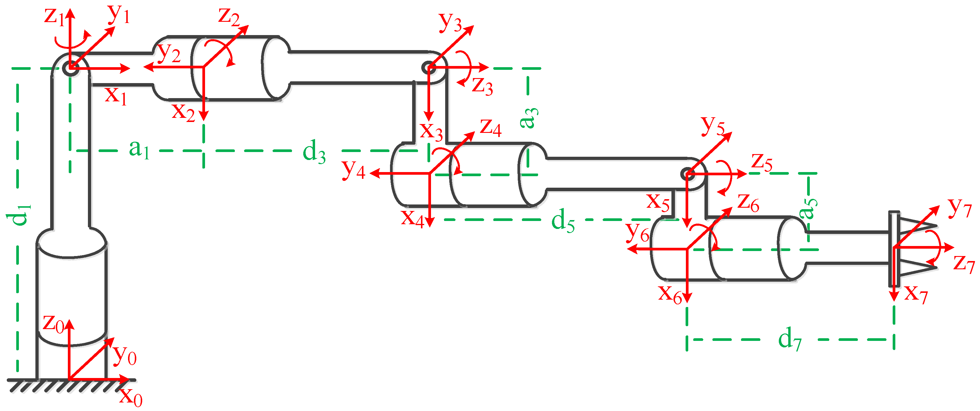
A redundant robot manipulator is selected as the simulation subject. Its structure diagram is shown in Figure 3. Its kinematic DH parameters are shown in Table 1. The weighted hybrid force/position control accuracy is analyzed while the redundant robot manipulator wipes or transports a workpiece. The length, width, and height of the cuboid workpiece are 0.055, 0.035, and 0.035 m, respectively; and its mass is 0.3 kg. Simulations are performed to analyze the position and force accuracies of the end-effector or the workpiece and verify the effectiveness of the proposed control algorithm. Its superiority is verified through comparative simulations.
A simulation of the wiping motion of the redundant robot manipulator is designed to verify the applicability of the proposed algorithm for robot compliant control. Two transport simulations are designed to verify its effectiveness in the case that the workpiece is moving in the clamping force direction. Three different control algorithms are adopted to design the controller for the wiping motion simulation, and their characteristics and differences are analyzed. The three control algorithms are the adaptive impedance voltage control algorithm (AIVC) [30], GNNPFSLC [21], and VBWHFPC, as shown in (18). For transport simulations, the workpiece is in free motion, and it is not in contact with the environment; consequently, compliant control is inapplicable. That is, AIVC is inapplicable. Only GNNPFSLC and VBWHFPC are adopted to design the controller, and their characteristics and advantages are analyzed.
Among the control objectives of the hybrid force/position control algorithm are the terminal position and orientation rather than joint angles. Therefore, if no special requirements for joint angles exist, then the minimum norm solution can be selected to simplify the controller. That is, ε = O n × 1 . In the subsequent simulations, ε among the control laws of the above three control algorithms would be O n × 1 .
Assuming that the end-effector is firmly installed at the terminal of the redundant robot manipulator by the fixture during the wiping operation, the end-effector and the redundant robot manipulator can be regarded as a whole. The center of mass of the workpiece is assumed to coincide with the origin of the terminal coordinate frame of the redundant robot manipulator during transport operations. Hence, the position accuracy of the end-effector or the center of mass of the workpiece is the terminal position accuracy of the redundant robot manipulator.

4.1. Wiping Operation of the Redundant Robot Manipulator

The redundant robot manipulator wipes in the XY plane, and the end-effector moves along the Y-axis direction within 10 s at a constant speed, as shown in (30). The wiping force is applied in the X-axis direction, as shown in (31). Then, the simulations are performed by adopting the above three control algorithms, and their position and force control accuracies are compared.
P y d = 0.01 t 0 < t 10
where P y d is the desired terminal position of the redundant robot manipulator in the Y-axis direction, and t is the operation time.
F x d = 10 0 < t 10
where F x d is the desired terminal force of the redundant robot manipulator in the X-axis direction.
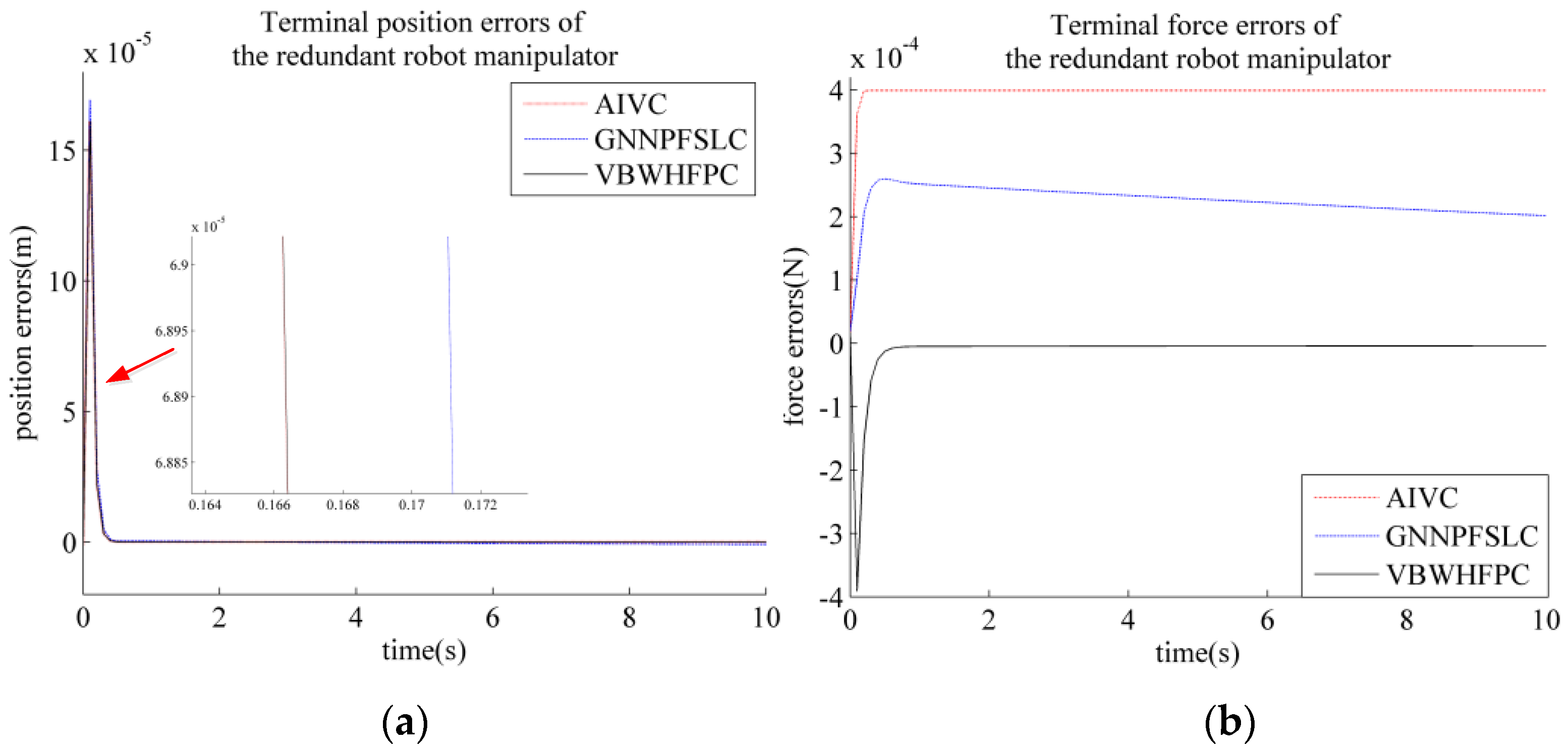
For the above three control algorithms, the terminal position and force errors of the redundant robot manipulator are shown in Figure 4. Their maximum absolute value of the terminal position errors | e P | m a x and terminal force error | e F | m a x are presented in Table 2.
P x , P y , and P z are the actual terminal position of the redundant robot manipulator in the X-axis, Y-axis, and Z-axis direction, respectively; F x , F y , and F z are the actual terminal force of the redundant robot manipulator in the X-axis, Y-axis, and Z-axis direction, respectively.
Table 2 presents that the position accuracies of AIVC, GNNPFSLC, and VBWHFPC in the Y-axis direction are 1.611 × 10⁻⁴, 1.694 × 10⁻⁴, and 1.612 × 10⁻⁴ m, respectively. Their force accuracies in the X-axis direction are 3.991 × 10⁻⁴, 2.598 × 10⁻⁴, and 3.910 × 10⁻⁴ N. The simulation results show that their position and force accuracies have a minimal difference, and they can meet the general industrial needs. Accordingly, VBWHFPC can be suitable for the compliance control of redundant robot manipulators.

4.2. Transport Operations of the Redundant Robot Manipulator

4.2.1. The Workpiece Moves along a Straight Line under Constant Force

The desired linear trajectory along the Z-axis direction is designed, as shown in (32). The workpiece moves within 10 s at an accelerated speed, a constant speed, and a decelerated speed in turn. The desired generalized force can be obtained by force analysis of the workpiece and Newton’s third law, as shown in (33). Then, the simulations are conducted by adopting GNNPFSLC and VBWHFPC, and their position and force control accuracies are compared.
P t z d = { 0.005 t 2 0 t 2 0.02 + 0.02 ( t 2 ) 2 < t 8 0.14 + 0.02 ( t 8 ) 0.005 ( t 8 ) 2 8 < t 10
where P t z d is the desired position of the center of mass of the workpiece in the Z-axis direction.
F z d = { 2.943 0 t 2 2.94 2 < t 8 2.937 8 < t 10
where F z d is the desired terminal force of the redundant robot manipulator in the Z-axis direction.
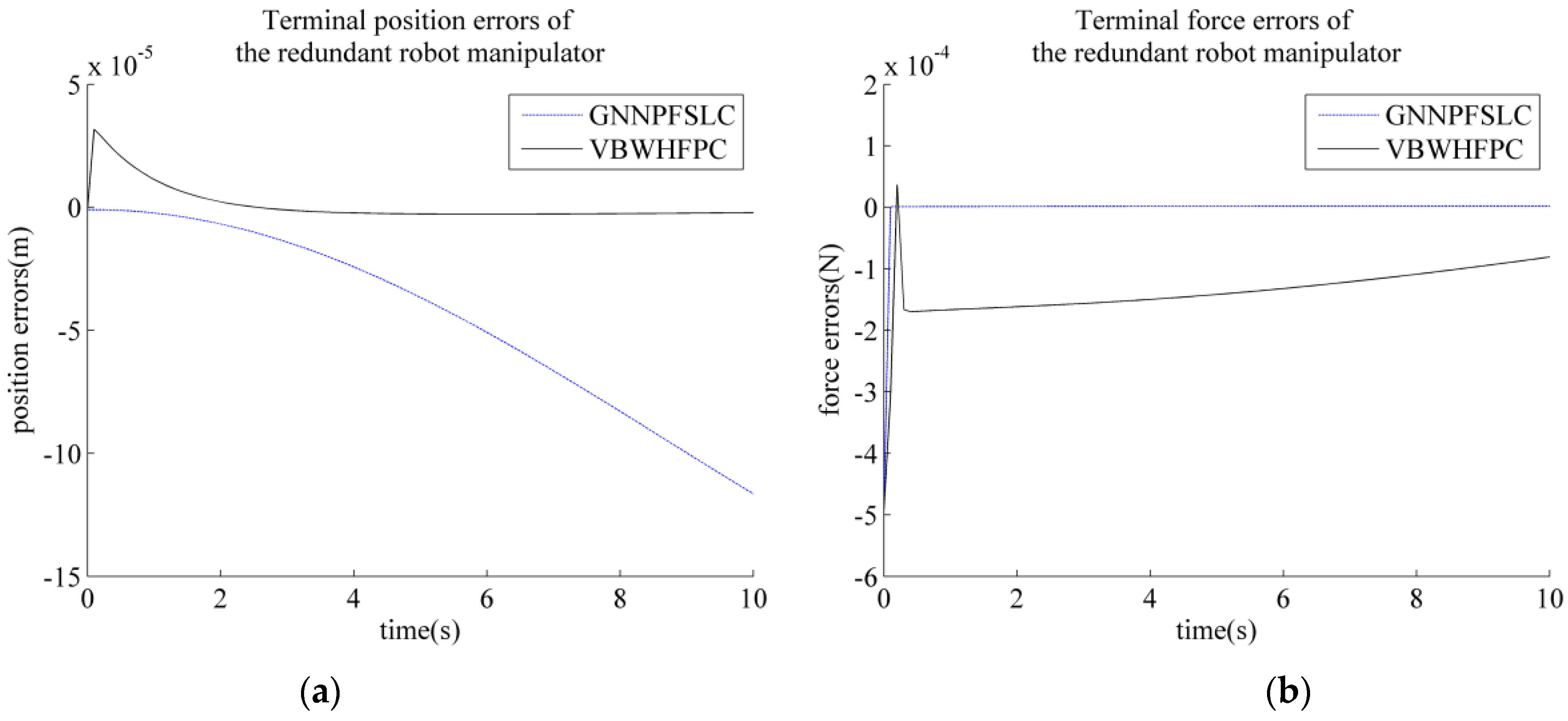
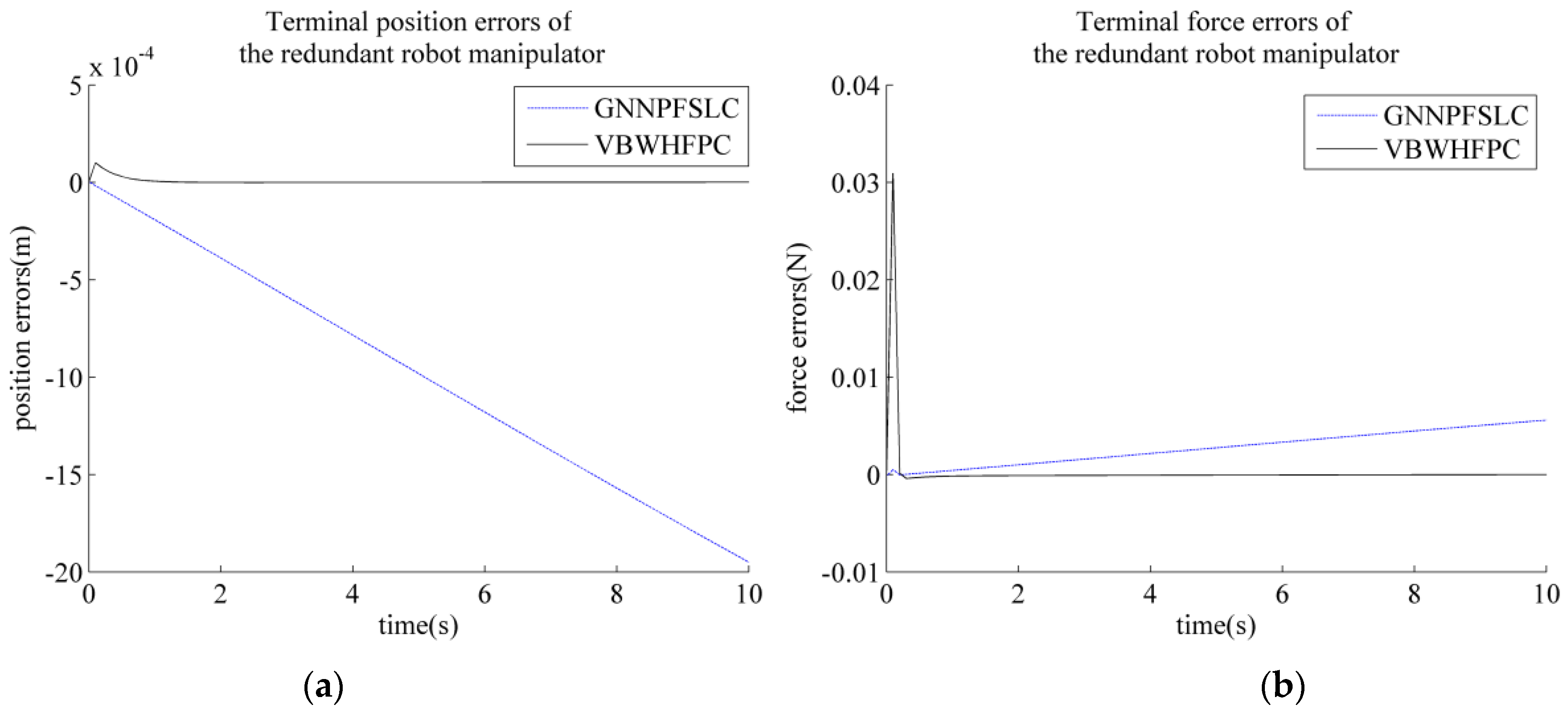
For the above two control algorithms, the terminal position and force errors of the redundant robot manipulator are shown in Figure 5. Their maximum absolute value of the terminal position errors | e P | m a x and terminal force error | e F | m a x are presented in Table 3.
Table 3 indicates that the position and force accuracies of GNNPFSLC in the Z-axis direction are 1.871 × 10⁻³ m and 5.507 × 10⁻³ N, respectively. Compared with VBWHFPC, its position accuracy is two orders of magnitude lower, and its force accuracy is slightly lower. Its position accuracy obviously cannot meet the general industrial needs; hence, GNNPFSLC cannot guarantee position and force accuracies at the same time under constant force.
The position and force accuracies of VBWHFPC in the Z-axis direction are 4.265 × 10⁻⁵ m and 3.004 × 10⁻³ N, respectively. They can meet the general industrial needs. Compared with GNNPFSLC, VBWHFPC has higher position and force accuracies. Thus, VBWHFPC can guarantee position and force accuracies at the same time under constant force.

4.2.2. The Workpiece Moves along an Arc under Variable Force

The desired arc trajectory in the YZ plane is designed, as shown in (34). The desired generalized force can be obtained by force analysis of the workpiece and Newton’s third law, as shown in (35). Afterward, the simulations are conducted by adopting GNNPFSLC and VBWHFPC, and their position and force control accuracies are compared.
P t y d = 0.15 + 0.15 sin ( π 30 t π 2 ) P t z d = 0.15 cos ( π 30 t π 2 ) 0 < t 10
where P t y d is the desired position of the center of mass of the workpiece in the Y−axis direction.
F y d = 5 × p i 2 sin ( π 30 t π 2 ) × 10 5 F z d = 2.94 + 5 × p i 2 cos ( π 30 t π 2 ) × 10 5 0 < t 10
where F y d is the desired terminal force of the redundant robot manipulator in the Y-axis direction.
For the above two control algorithms, the terminal position and force errors of the redundant robot manipulator are shown in Figure 6 and Figure 7. Their maximum absolute value of the terminal position errors | e P | m a x and terminal force error | e F | m a x are presented in Table 4.
Table 4 presents that the position and force accuracies of GNNPFSLC in the Y-axis direction are 1.165 × 10⁻⁴ m and 4.933 × 10⁻⁴ N, respectively. Compared with VBWHFPC, its force accuracy is almost the same, but its position accuracy is one order of magnitude lower. The position and force accuracies of GNNPFSLC in the Z-axis direction are 1.950 × 10⁻³ m and 5.587 × 10⁻³ N, respectively. Compared with VBWHFPC, its force accuracy is one order of magnitude higher, but its position accuracy is one order of magnitude lower and obviously cannot meet the general industrial needs. GNNPFSLC cannot guarantee position and force accuracies at the same time under variable force.
The position and force accuracies of VBWHFPC in the Y- and Z-axis directions are 3.171 × 10⁻⁵ and 9.995 × 10⁻⁵ m and 4.936 × 10⁻⁴ and 3.094 × 10⁻² N, respectively. They can meet the general industrial needs. Compared with GNNPFSLC, its force accuracy is lower, but its position accuracy is higher. VBWHFPC can guarantee position and force accuracies at the same time under variable force.

5. Experiment

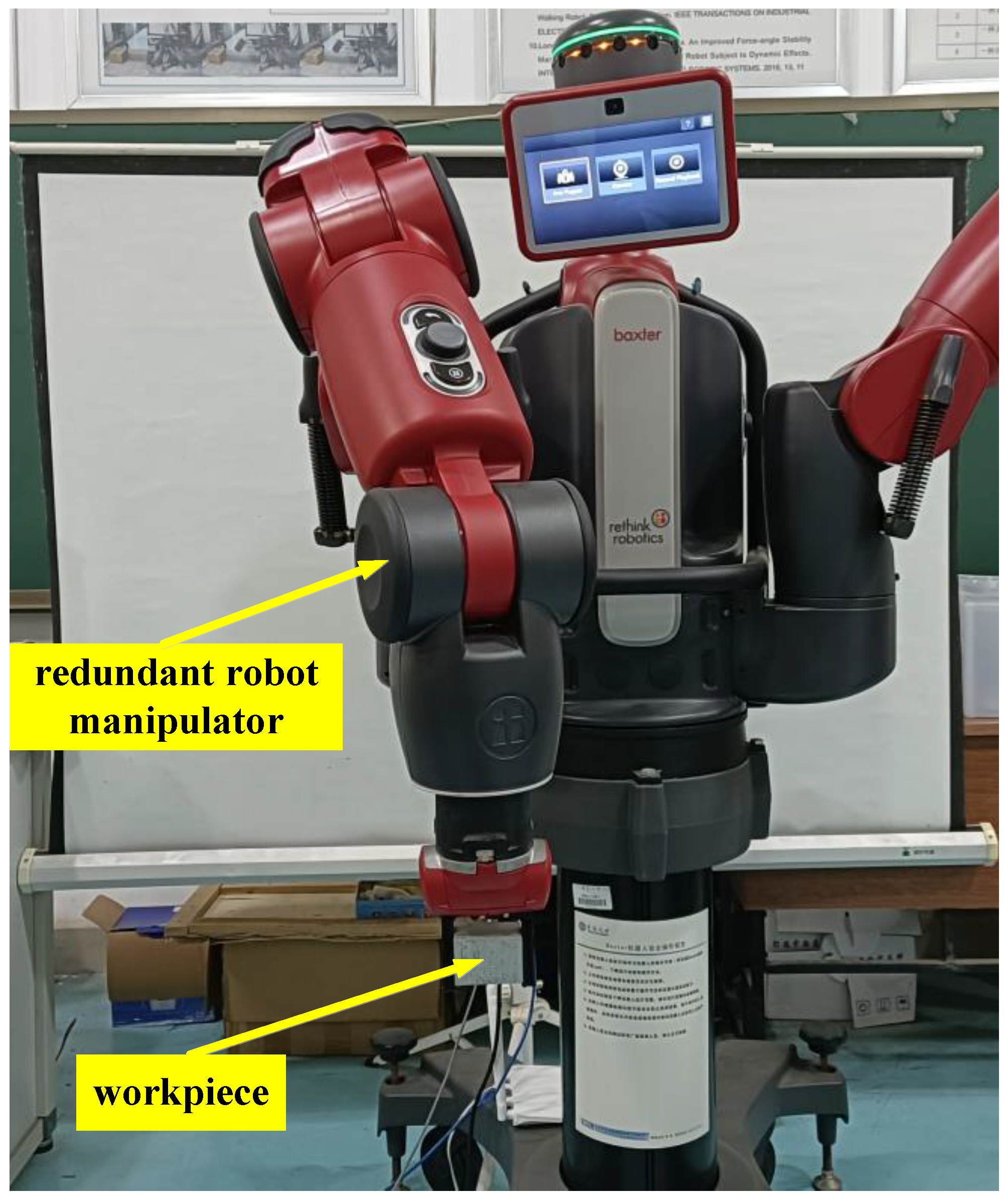
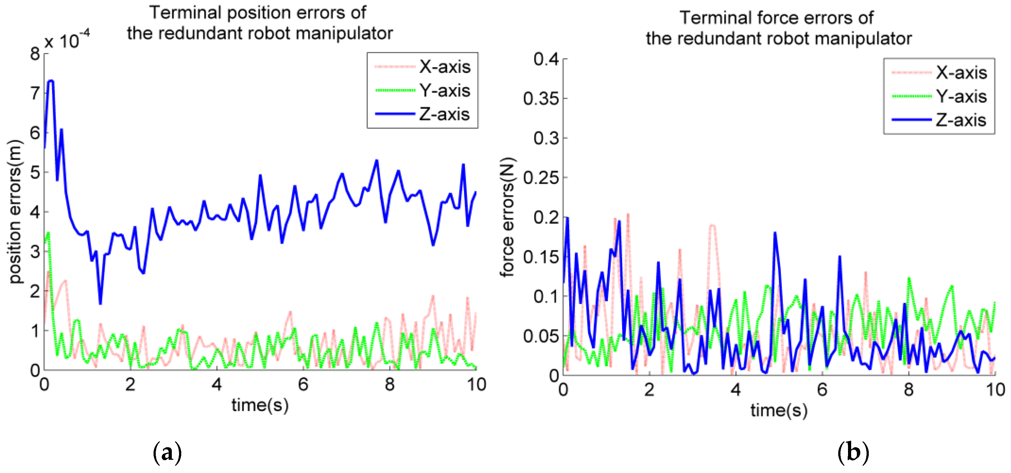
To verify the effectiveness of the proposed control algorithm, the Baxter redundant robot manipulator of Rethink Company is taken as the experimental object, as shown in Figure 8. The redundant robot manipulator transports a workpiece along the trajectory (30). This workpiece is the same as the one in the simulation. The terminal position and force errors of the redundant robot manipulator are shown in Figure 9. Their maximum absolute value of the terminal position errors | e P | m a x and terminal force error | e F | m a x are presented in Table 5.
Table 5 indicates that the position and force accuracies of VBWHFPC in the Y- and Z-axis directions are 3.489 × 10⁻⁴ and 7.313 × 10⁻⁴ m and 1.238 × 10⁻¹ and 1.997 × 10⁻¹ N, respectively. They can meet the general industrial needs. Therefore, VBWHFPC can satisfy the control accuracy of position and force simultaneously. It can be effectively applied to the hybrid force/position control.

6. Conclusions

A novel voltage-based weighted hybrid force/position control algorithm is proposed for redundant robot manipulators to guarantee the position and force accuracies in the force direction of the workpiece during operations and simplify the controller for reducing the algorithm complexity. Mapping between voltage and the terminal position and orientation is first established. The voltage-based control algorithm is improved on the basis of the above mapping and then combined with the hybrid force/position control algorithm. To avoid the problems of space decomposition and switching, the force and position control laws are summed directly through a weighted way, and the selection matrix is eliminated. A selection method for weighted coefficient based on Lyapunov stability theory is provided. To verify the superiority of the proposed algorithm, comparative simulations are performed. Results show that position and force accuracies of the impedance control algorithm, the hybrid force/position control algorithm, and the proposed algorithm during the wiping operation of the redundant robot manipulator are 10−4 to 10−5 m and 10−4 to 10−5 N, respectively. Three algorithms all can guarantee position and force accuracies simultaneously. Hence, the proposed algorithm can be suitable for compliant operations of the redundant robot manipulator. Force accuracy of the hybrid force/position control algorithm during the transport operations of the redundant robot manipulator is 10−3 to 10−4 N, but its position accuracy in the Z-axis direction is more than 10−3 m. Therefore, the hybrid force/position control algorithm can guarantee only the force accuracy in the force direction but not the position accuracy in the force direction. Position and force accuracies of the proposed algorithm during the transport operations of the redundant robot manipulator are 10−4 to 10−5 m and 10−2 to 10−4 N, respectively. Hence, the proposed algorithm can guarantee position and force accuracies simultaneously, and its position accuracy is several orders of magnitude higher than the one of the hybrid force/position control algorithm. To verify the effectiveness of the proposed algorithm, the transport experiment in the YZ plane is conducted. Results show that position and force accuracies in the Y- and Z-axis directions are 3.489 × 10⁻⁴ and 7.313 × 10⁻⁴ m and 1.238 × 10⁻¹ and 1.997 × 10⁻¹ N, respectively. They can meet the general industrial needs. Therefore, the proposed algorithm can cover the shortages of impedance control and hybrid force/position control, and it is more general. It can effectively meet the requirement and accuracy of operations for redundant robot manipulators.
On the premise of guaranteeing stability, only the value range of weighted coefficients has been provided. Therefore, the selection method of the optimal weighted coefficients will be studied in the future research work.

Author Contributions

Conceptualization, J.D. and H.D.; methodology, J.D.; software, J.D. and Y.Z.; validation, J.D., Y.Z. and H.D.; formal analysis, J.D., Y.Z. and H.D.; investigation, J.D. and H.D.; resources, H.D.; data curation, J.D.; writing—original draft preparation, J.D.; writing—review and editing, Y.Z. and H.D.; visualization, J.D.; supervision, Y.Z. and H.D.; project administration, Y.Z. and H.D.; funding acquisition, H.D. All authors have read and agreed to the published version of the manuscript.

Funding

This work was supported in part by the National Key Research and Development Project under Grants 2018YFB1307203 and 2019YFC1511503, and in part by the Project of State Key Laboratory of High Performance Complex Manufacturing, Central South University under Grant ZZYJKT2021-17.

Institutional Review Board Statement

Not applicable.

Informed Consent Statement

Not applicable.

Data Availability Statement

Not applicable.

Acknowledgments

The authors acknowledge the fund of National Key Research and Development Project (grants no. 2018YFB1307203 and no. 2019YFC1511503), and the fund of Project of State Key Laboratory of High Performance Complex Manufacturing, Central South University (grant no. ZZYJKT2021).

Conflicts of Interest

The authors declare no conflict of interest.

References

  1. Al-Darraji, I.; Piromalis, D.; Kakei, A.A.; Khan, F.Q.; Stojmenovic, M.; Tsaramirsis, G.; Papageorgas, P.G. Adaptive Robust Controller Design-Based RBF Neural Network for Aerial Robot Arm Model. Electronics 2021, 10, 831. [Google Scholar] [CrossRef]
  2. Cheng, X.; Tu, X.; Zhou, Y.; Zhou, R. Active Disturbance Rejection Control of Multi-Joint Industrial Robots Based on Dynamic Feedforward. Electronics 2019, 8, 591. [Google Scholar] [CrossRef] [Green Version]
  3. Bouyarmane, K.; Chappellet, K.; Vaillant, J.; Kheddar, A. Quadratic Programming for Multirobot and Task-Space Force Control. IEEE Trans. Robot. 2019, 35, 64–77. [Google Scholar] [CrossRef]
  4. Su, Y.; Zheng, C.; Mercorelli, P. Robust approximate fixed-time tracking control for uncertain robot manipulators. Mech. Syst. Signal Process. 2020, 135, 106379. [Google Scholar] [CrossRef]
  5. Moe, S.; Gravdahl, J.T.; Pettersen, K.Y. Set-based Control for Autonomous Spray Painting. IEEE Trans. Autom. Sci. Eng. 2018, 15, 1785–1796. [Google Scholar] [CrossRef]
  6. Kovacs, A. Integrated task sequencing and path planning for robotic remote laser welding. Int. J. Prod. Res. 2016, 54, 1210–1224. [Google Scholar] [CrossRef]
  7. Alonso-Mora, J.; Baker, S.; Rus, D.L. Multi-robot formation control and object transport in dynamic environments via constrained optimization. Int. J. Robot. Res. 2017, 36, 1000–1021. [Google Scholar] [CrossRef]
  8. Liu, S.; Li, Y.F.; Xing, D. Sensing and Control for Simultaneous Precision Peg-in-Hole Assembly of Multiple Objects. IEEE Trans. Autom. Sci. Eng. 2020, 17, 310–324. [Google Scholar] [CrossRef]
  9. Zhang, Z.; Chen, S.; Zhu, X.; Yan, Z. Two Hybrid End-Effector Posture-Maintaining and Obstacle-Limits Avoidance Schemes for Redundant Robot Manipulators. IEEE Trans. Ind. Inform. 2020, 16, 754–763. [Google Scholar] [CrossRef]
  10. Zhang, H.; Jin, H.; Liu, Z.; Liu, Y.; Zhu, Y.; Zhao, J. Real-time Kinematic Control for Redundant Manipulators in a Time-varying Environment: Multiple-dynamic Obstacle Avoidance and Fast Tracking of a Moving Object. IEEE Trans. Ind. Inform. 2020, 16, 28–41. [Google Scholar] [CrossRef]
  11. Chang, Q.; Wang, H.; Wang, D.; Zhang, H.; Li, K.; Yu, B. Motion Planning for Vibration Reduction of a Railway Bridge Maintenance Robot with a Redundant Manipulator. Electronics 2021, 10, 2793. [Google Scholar] [CrossRef]
  12. Izadbakhsh, A.; Khorashadizadeh, S.; Ghandali, S. Robust adaptive impedance control of robot manipulators using Szász-Mirakyan operator as universal approximator. ISA Trans. 2020, 106, 1–11. [Google Scholar] [CrossRef]
  13. Cao, H.; Chen, X.; He, Y.; Zhao, X. Dynamic Adaptive Hybrid Impedance Control for Dynamic Contact Force Tracking in Uncertain Environments. IEEE Access 2019, 7, 83162–83174. [Google Scholar] [CrossRef]
  14. Li, Z.; Yang, D.; Zhou, H.; Cao, H. Research of a Self-adaptive Robot Impedance Control Method for Robot-Environment Interaction. Adv. Intell. Syst. Comput. 2015, 345, 221–238. [Google Scholar]
  15. Wei, C.; Shen, Z.; Xiao, D.; Wang, L.; Bai, X.; Chen, H. An optimal scheduling strategy for peer-to-peer trading in interconnected microgrids based on RO and Nash bargaining. Appl. Energy 2021, 295, 117024. [Google Scholar] [CrossRef]
  16. Xiao, D.; AlAshery, M.K.; Qiao, W. Optimal Price-Maker Trading Strategy of Wind Power Producer using Virtual Bidding. J. Mod. Power Syst. Clean Energy 2021, 1–13. [Google Scholar] [CrossRef]
  17. Erickson, D.; Weber, M.; Sharf, I. Contact Stiffness and Damping Estimation for Robotic Systems. Int. J. Robot. Res. 2003, 22, 41–57. [Google Scholar] [CrossRef]
  18. Yokokura, Y.; Ohishi, K.; Katsura, S. Fine Force Reproduction Based on Motion-Copying System Using Acceleration Observer. IEEE Trans. Ind. Electron. 2014, 61, 6213–6221. [Google Scholar] [CrossRef]
  19. Komada, S.; Machii, N.; Hori, T. Control of redundant manipulators considering order of disturbance observer. IEEE Trans. Ind. Electron. 2000, 47, 413–420. [Google Scholar] [CrossRef]
  20. Navvabi, H.; Markazi, A.H.D. Hybrid position/force control of Stewart Manipulator using Extended Adaptive Fuzzy Sliding Mode Controller (E-AFSMC). ISA Trans. 2019, 88, 280–295. [Google Scholar] [CrossRef]
  21. Li, L.; Xie, L.; Luo, X.; Wang, Z. Compliance Control Using Hydraulic Heavy-Duty Manipulator. IEEE Trans. Ind. Inform. 2019, 15, 1193–1201. [Google Scholar] [CrossRef]
  22. Kumar, N.; Rani, M. A new hybrid force/position control approach for time-varying constrained reconfigurable manipulators. ISA Trans. 2020, 110, 138–147. [Google Scholar] [CrossRef]
  23. Baek, J.; Jung, J. A Model-Free Control Scheme for Attitude Stabilization of Quadrotor Systems. Electronics 2020, 9, 1586. [Google Scholar] [CrossRef]
  24. Li, M.; Kang, R.; Branson. D.; Dai, J. Model-Free Control for Continuum Robots Based on an Adaptive Kalman Filter. IEEE/ASME Trans. Mech. 2018, 23, 286–297. [Google Scholar] [CrossRef]
  25. Zheng, C.; Su, Y.; Mercorelli, P. A simple nonlinear PD control for faster and high-precision positioning of servomechanisms with actuator saturation. Mech. Syst. Signal Process. 2019, 121, 215–226. [Google Scholar] [CrossRef]
  26. Gao, P.; Zhang, G.; Lv, X. Model-Free Hybrid Control with Intelligent Proportional Integral and Super-Twisting Sliding Mode Control of PMSM Drives. Electronics 2020, 9, 1427. [Google Scholar] [CrossRef]
  27. Keel, L.H.; Bhattacharyya, S.P. Controller Synthesis Free of Analytical Models: Three Term Controllers. IEEE Trans. Autom. Control 2008, 53, 1353–1369. [Google Scholar] [CrossRef]
  28. Martin, S.C.; Whitcomb, L.L. Nonlinear Model-Based Tracking Control of Underwater Vehicles with Three Degree-of-Freedom Fully Coupled Dynamical Plant Models: Theory and Experimental Evaluation. IEEE Trans. Control Syst. Trans. 2018, 26, 404–414. [Google Scholar] [CrossRef]
  29. Fateh, M.M. On the Voltage-Based Control of Robot Manipulators. Int. J. Control Autom. 2008, 6, 702–712. [Google Scholar]
  30. Fateh, M.M.; Khoshdel, V. Voltage-based adaptive impedance force control for a lower-limb rehabilitation robot. Adv. Robot. 2015, 29, 961–971. [Google Scholar] [CrossRef]
  31. Veysi, M.; Soltanpour, M.R. Voltage-Base Control of Robot Manipulator Using Adaptive Fuzzy Sliding Mode Control. Int. J. Fuzzy Syst. 2017, 19, 1430–1443. [Google Scholar] [CrossRef]
  32. Zaare, S.; Soltanpour, M.R.; Moattari, M. Voltage based sliding mode control of flexible joint robot manipulators in presence of uncertainties. Robot. Auton. Syst. 2019, 118, 204–219. [Google Scholar] [CrossRef]
  33. Xu, Q. Robust Impedance Control of a Compliant Microgripper for High-Speed Position/Force Regulation. IEEE Trans. Ind. Electron. 2015, 62, 1201–1209. [Google Scholar] [CrossRef]
  34. Jiang, J.; Liu, J.; Chen, W.; Wen, C.; Chen, W. An Impedance-Based Force Control Scheme to a Plate-to-Plate Nanoimprinter. IEEE Trans. Nanotechnol. 2016, 15, 328–336. [Google Scholar] [CrossRef]
  35. Xu, S.; He, B.; Zhou, Y.; Wang, Z.; Zhang, C. A Hybrid Position/Force Control Method for a Continuum Robot with Robotic and Environmental Compliance. IEEE Access 2019, 7, 100467–100479. [Google Scholar] [CrossRef]
  36. Pomares, J.; Torres, F. Movement-Flow-Based Visual Servoing and Force Control Fusion for Manipulation Tasks in Unstructured Environments. IEEE Trans. Syst. Man Cybern. C 2005, 35, 4–15. [Google Scholar] [CrossRef]
  37. Isermann, R. Estimation of physical parameters for dynamic processes with application to an industrial robot. Int. J. Control 2002, 55, 1287–1298. [Google Scholar] [CrossRef]
  38. Xin, G.; Deng, H.; Zhong, G. Closed-form dynamics of a 3-DOF spatial parallel manipulator by combining the Lagrangian formulation with the virtual work principle. Nonlinear Dyn. 2016, 86, 1329–1347. [Google Scholar] [CrossRef]
  39. Li, H.; Zhao, Y.; Li, B.; Li, G.; Cui, L. Torque Calculation of Permanent Magnet Spherical Motor Based on Virtual Work Method. IEEE Trans. Ind. Electron. 2020, 67, 7736–7745. [Google Scholar] [CrossRef]
  40. Mansard, N.; Chaumette, F. Directional Redundancy for Robot Control. IEEE Trans. Autom. Control 2009, 54, 1179–1192. [Google Scholar] [CrossRef] [Green Version]
  41. Colomé, A.; Torras, C. Closed-Loop Inverse Kinematics for Redundant Robots: Comparative Assessment and Two Enhancements. IEEE/ASME Trans. Mech. 2015, 20, 944–955. [Google Scholar] [CrossRef] [Green Version]
  42. Xu, W.; Zhang, J.; Liang, B.; Li, B. Singularity Analysis and Avoidance for Robot Manipulators with Nonspherical Wrists. IEEE Trans. Ind. Electron. 2016, 63, 277–290. [Google Scholar] [CrossRef]
  43. Fateh, M.M.; Babaghasabha, R. Impedance control of robots using voltage control strategy. Nonlinear Dyn. 2013, 74, 277–286. [Google Scholar] [CrossRef]
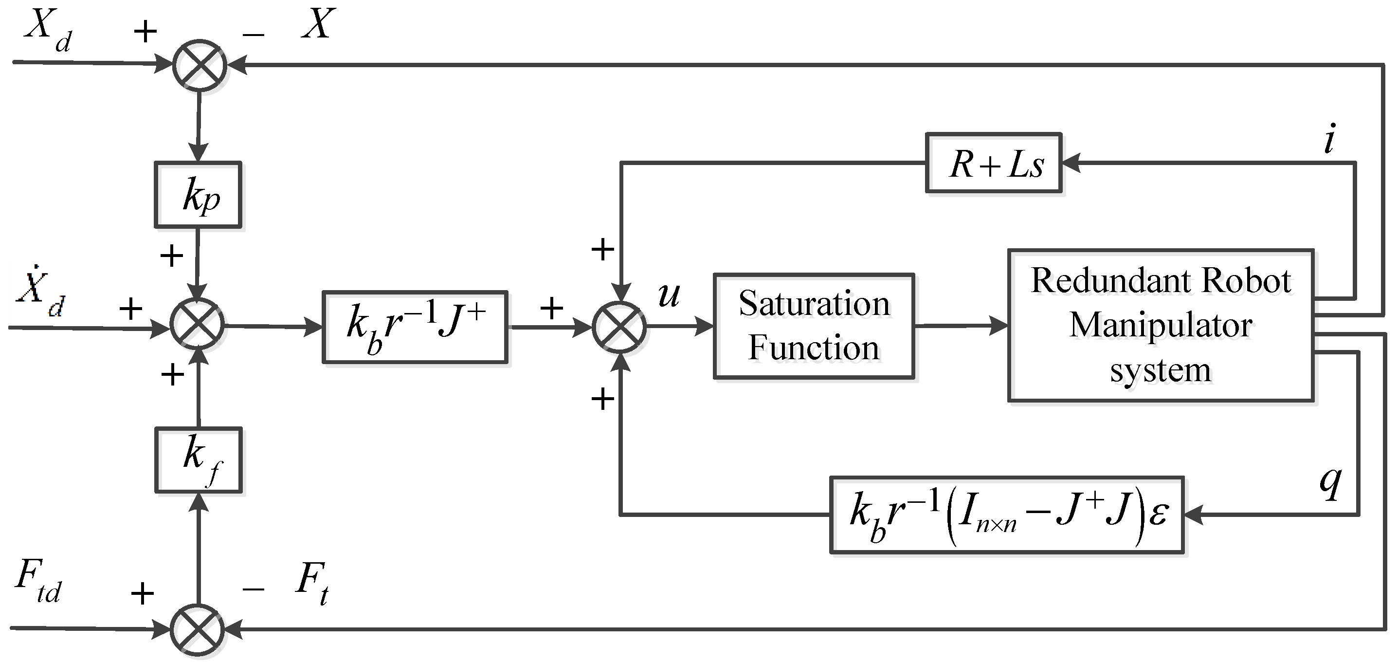
Figure 1. Voltage-based weighted hybrid force/position control strategy.
Electronics 11 00179 g001
Figure 2. Distribution of the generalized terminal force between the end-effector and the workpiece at the center of mass of the workpiece; (a) the workpiece is in free motion (b) the workpiece is in contact with the environment.
Electronics 11 00179 g002
Figure 3. Structure diagram of the redundant robot manipulator.
Electronics 11 00179 g003
Figure 4. Control accuracy of the above three algorithms (a) position control in the Y-axis direction; (b) force control in the X-axis direction.
Electronics 11 00179 g004
Figure 5. Control accuracy of the above two algorithms in the Z-axis direction (a) position control; (b) force control.
Electronics 11 00179 g005
Figure 6. Control accuracy of the above two algorithms in the Y-axis direction (a) position control; (b) force control.
Electronics 11 00179 g006
Figure 7. Control accuracy of the above two algorithms in the Z-axis direction (a) position control; (b) force control.
Electronics 11 00179 g007
Figure 8. Redundant robot manipulator.
Electronics 11 00179 g008
Figure 9. Control accuracy of the proposed algorithm (a) position control; (b) force control.
Electronics 11 00179 g009
Table 1. DH parameters of the redundant robot manipulator.
Joint iai−1 (mm)αi−1 (°)di (mm)θi (°)
100270.350
269−90090
3090364.350
469−9000
5090374.290
610−9000
7090229.5250
Table 2. Position and force accuracies during the wiping operation.
| e P | m a x | e F | m a x
P x ( m ) P y ( m ) P z ( m ) F x ( N ) F y ( N ) F z ( N )
AIVC4.000 × 10−51.611 × 10−43.029 × 10−63.991 × 10−49.398 × 10−169.398 × 10⁻¹⁶
GNNPFSLC2.607 × 10−51.694 × 10−43.029 × 10−62.598 × 10−49.398 × 10−169.398 × 10⁻¹⁶
VBWHFPC3.901 × 10−51.612 × 10−43.029 × 10−63.910 × 10−49.398 × 10−169.398 × 10⁻¹⁶
Table 3. Position and force accuracies during the transport operation under constant force.
| e P | m a x | e F | m a x
P x ( m ) P y ( m ) P z ( m ) F x ( N ) F y ( N ) F z ( N )
GNNPFSLC1.629 × 10−61.082 × 10−51.871 × 10−31.150 × 10−319.389 × 10−165.507 × 10⁻³
VBWHFPC1.629 × 10−66.865 × 10−54.265 × 10−51.150 × 10−319.389 × 10−163.004 × 10⁻³
Table 4. Position and force accuracies during the transport operation under variable force.
| e P | m a x | e F | m a x
P x ( m ) P y ( m ) P z ( m ) F x ( N ) F y ( N ) F z ( N )
GNNPFSLC1.848 × 10−51.165 × 10−41.950 × 10−33.022 × 10−194.933 × 10−45.587 × 10−3
VBWHFPC3.819 × 10−53.171 × 10−59.995 × 10−53.022 × 10−194.936 × 10−43.094 × 10−2
Table 5. Position and force accuracies during the transport operation.
| e P | m a x | e F | m a x
P x ( m ) P y ( m ) P z ( m ) F x ( N ) F y ( N ) F z ( N )
VBWHFPC2.501 × 10−43.489 × 10−47.313 × 10−42.043 × 10−11.238 × 10−11.997 × 10⁻¹
Publisher’s Note: MDPI stays neutral with regard to jurisdictional claims in published maps and institutional affiliations.