Abstract
The high band pattern distortions in an 1810–2690 MHz frequency band, introduced due to low band radiators working in 690–960 MHz, are mitigated by a simple yet effective change to the low band-radiating elements. A novel horizontal and vertical radiating element is designed instead of a conventional slant polarized low band-radiating element to reduce the scattering. The slant polarization is achieved from the horizontal and vertical dipoles, using a 180° hybrid coupler. The vertical dipole length is optimized to improve the high band patterns. The experimental results verified that the proposed horizontal and vertical low band dipole result in the reduction of high band pattern distortions. The low band-radiating elements provide >12 dB return loss over the entire frequency band 690–960 MHz and provide comparable pattern performance to a conventional slant low band dipole.
1. Introduction
The growth in connected devices requires high connection density in 5G networks. In fact, requirements specify more than 1 million devices per square kilometer for 5G massive machine-type communication (mMTC), a 10-fold increase compared to 4G [1]. This is catered through small cell densification and improved spectrum utilization, which both require compact multiband antenna systems. The compactness and need for multiband antenna systems present conflicting demands, since the need for multiple bands requires multiple arrays and thus more space [2,3]. The only way to realize a compact antenna is to interleave these multiband arrays. The main challenge is to then ensure the radiation patterns are not distorted due to scattering from other radiating elements in the vicinity. In such multiband interleaved array, the high-frequency element patterns are impacted due to the scattering from the currents induced in low-frequency radiating elements and vice versa. The impact can be on multiple parameters such as beamwidth, squint, and cross-polarization discrimination (XPD). Often, it is attempted to ensure that each radiating element is transparent to each other in their operating frequency bands, which is a challenging task.
The common approach to reducing the crossband scattering is to adopt different sizes and shapes of metal cavities or walls [4,5,6,7]. Cavity-backed antenna is used in [8] to improve the isolation of antenna elements in an array. In [9], the high-frequency band (HB) pattern distortions caused by the lower frequency band (LB) radiating elements are minimized by introducing chokes into the LB element. These chokes are quarter-wavelength open-circuit segments at high band frequencies, which minimizes scattering. In [10], the printed dipole is segmented into smaller segments that are not resonant in the higher-frequency band region. Each segment is connected to the other by inductive thin lines. This makes the lower band elements transparent to the high band-radiating elements. In [11], a cloaked antenna system is realized to minimize the scattering of closely located antennas. Filtering techniques with different configurations are also employed to obtain better isolation between radiating elements. As in [12], the filtering antenna as array elements has been proposed. The radiating element realized the filtering response by adding the shorting pins and E-slot to reduce the crossband scattering. A coupled resonator-based decoupling network is deployed in [13] to improve crossband scattering. The currents induced by the coupled resonator help to suppress the strong coupling between the antennas operated in two frequency bands. The addition of a frequency-selective surface between the high band and low band elements has been deployed in [14] to reduce the crossband scattering. Although these techniques suppress the crossband scattering, they do require significant modifications to LB or HB elements which can increase the cost of manufacturing due to added complexity of products.
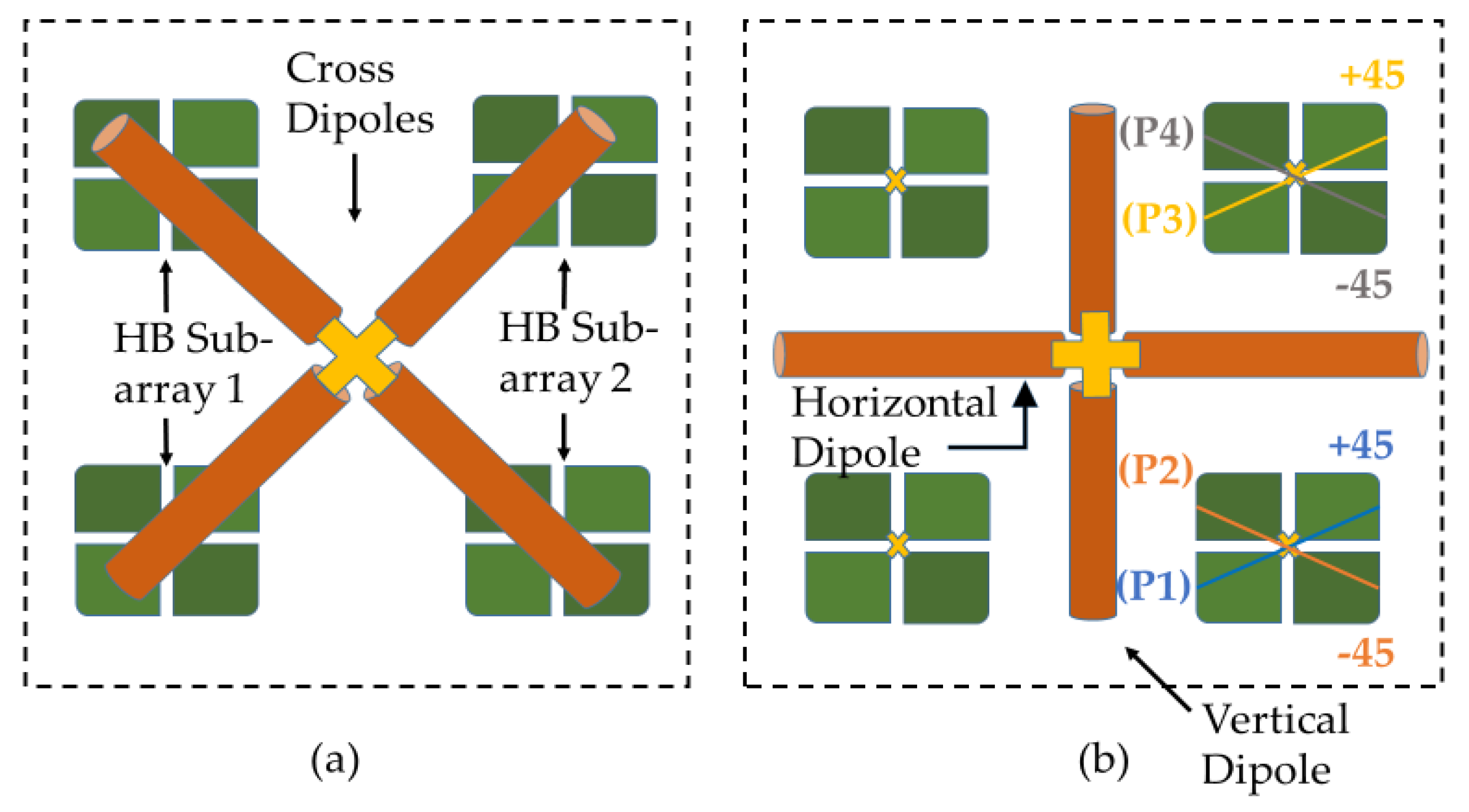
The novelty in this work is in the simple and effective approach proposed to reduce the crossband scattering at HB by orienting the LB radiating element in horizontal (H) and vertical (V) directions, as shown in Figure 1b, in contrast to the conventional slant LB dipole configuration shown in Figure 1a. The main challenge then is to generate the slant polarization (±45°) from an H and V oriented dipoles. This has been overcome by utilizing a 180° hybrid coupler. Below is a list of abbreviations in Table 1 to provide a better understanding of acronyms used in the proposed technique.
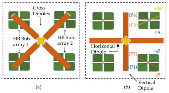
Figure 1.
(a) Slant dipole configuration used in traditional interleaved scheme for dual-band dual-polarized BSA. (b) The proposed horizontal and vertical LB dipole configuration (LBHV) with HB subarrays. P1 and P3 refer to +45 polarizations; P2 and P4 refer to −45 polarization.

Table 1.
List of Acronyms.
2. Low Band Horizontal and Vertical Configuration
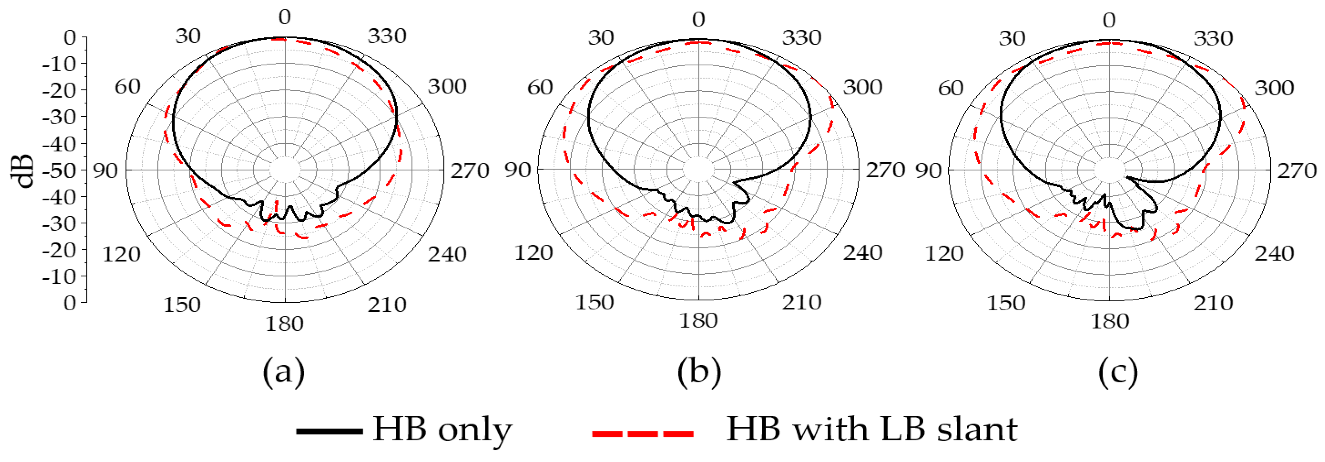
The HB and LB elements are interleaved in the current base station antenna (BSA) for space savings. Due to the use of ±45 polarized elements, the dipoles are oriented in a slant configuration, as shown in Figure 1a. It should be noted that a full array has multiple such elements arranged vertically, and that only a segment is depicted in this figure for clarity. The presence of the LB radiator on top of the HB radiators can induce HB currents on the LB dipoles, acting as resonating structures and distorting the patterns. In addition, being directly in front of the HB radiators disrupts the nearfield distribution and scatters the desired HB patterns. This results in undesirable HB patterns, as shown in Figure 2.
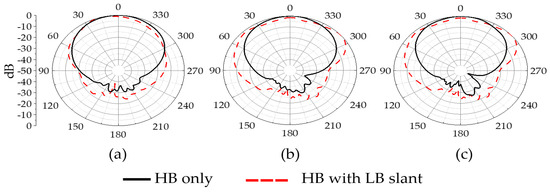
Figure 2.
High band-only and high band with slant LB antenna-measured azimuth patterns at (a) 1.8 GHz, (b) 2.4 GHz and (c) 2.6 GHz.
The aim of this work is to mitigate such HB pattern effects due to LB antenna element. The location of the dipoles of the LB antennas on top of the HB antenna elements was investigated. It was found that pattern distortions were significant as long as the LB dipole was directly above the HB antenna element, irrespective of the type of the HB radiator. This study uses a square-shaped cross-dipole antenna as the HB element [4]. The HB array itself, without any LB radiators, has cleaner patterns with half-power beamwidth (HPBW) around 65 ± 5° and almost no squint, as shown in Figure 2.
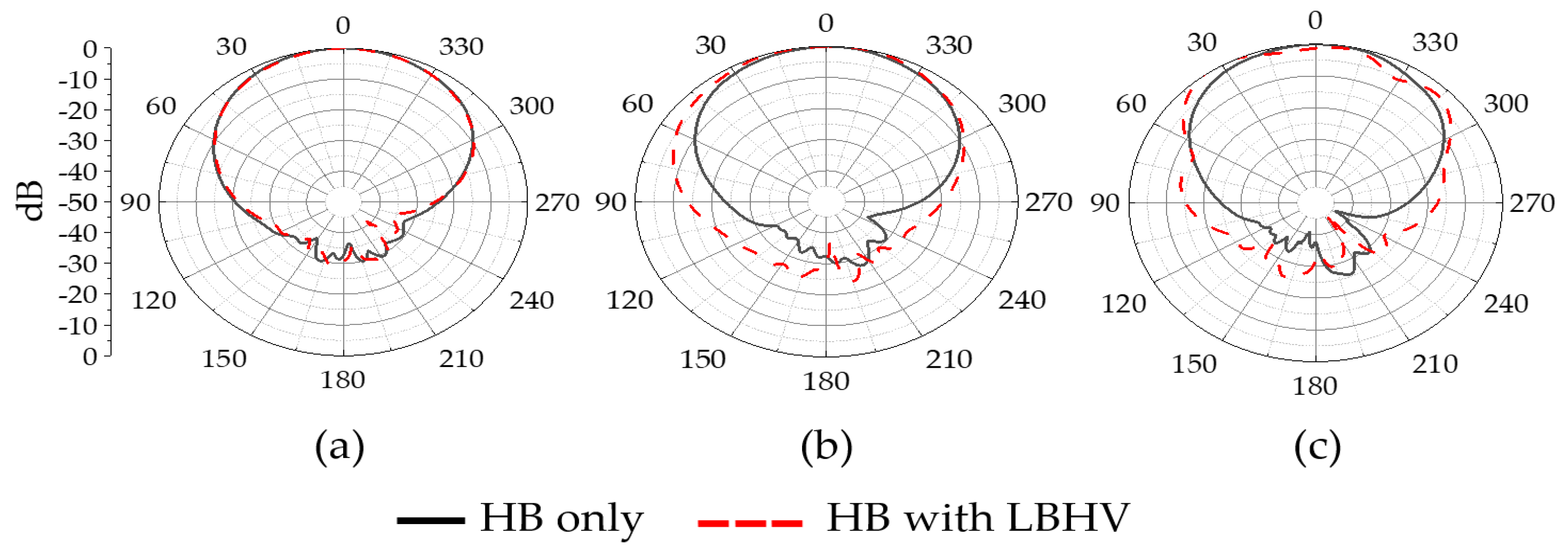
A careful observation of the current distribution at HB frequencies revealed that the induced HB currents reduce in magnitude as the LB dipoles are moved away from a slant position to horizontal and vertical positions. As a result, HB patterns are cleaner, as shown in Figure 3. This LB configuration is referred to as Low Band Horizontal–Vertical (LBHV) from here onwards. The measured results show that the pattern performance of HB arrays with LBHV elements is similar to HB-only radiation patterns.
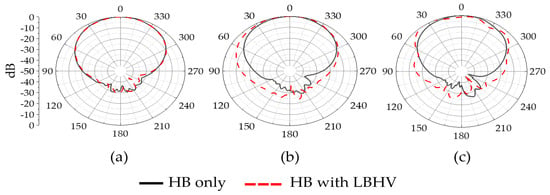
Figure 3.
High-band measured azimuth radiation patterns with a LBHV element at (a) 1.8 GHz, (b) 2.4 GHz, and (c) 2.6 GHz.
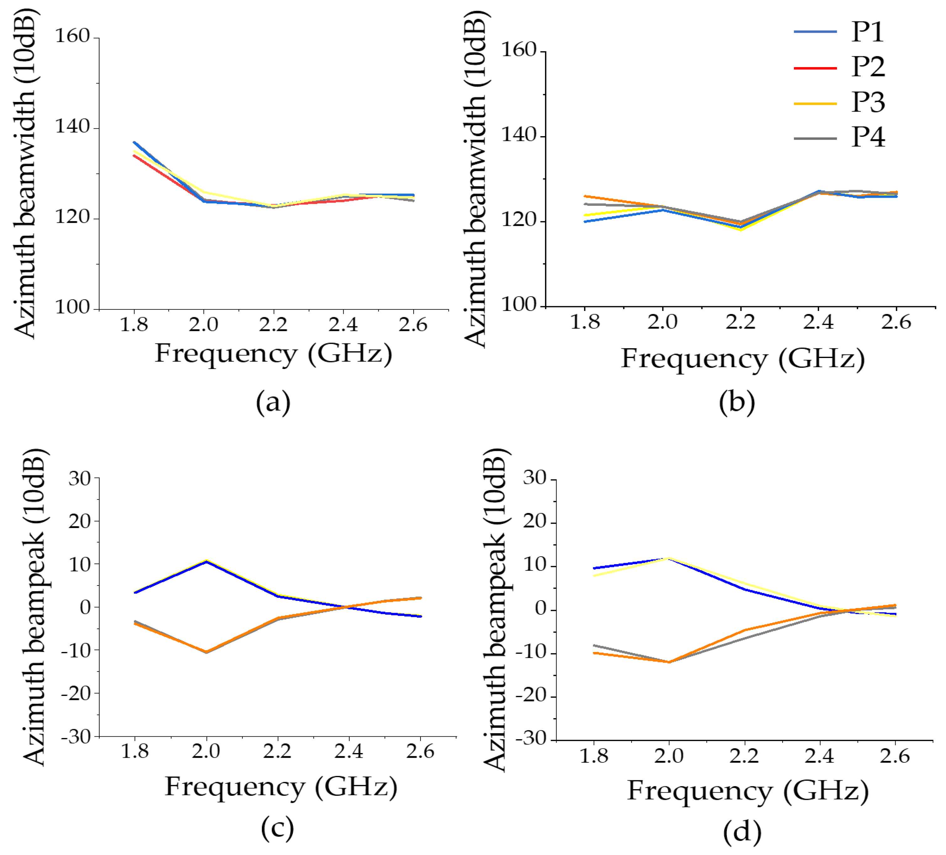
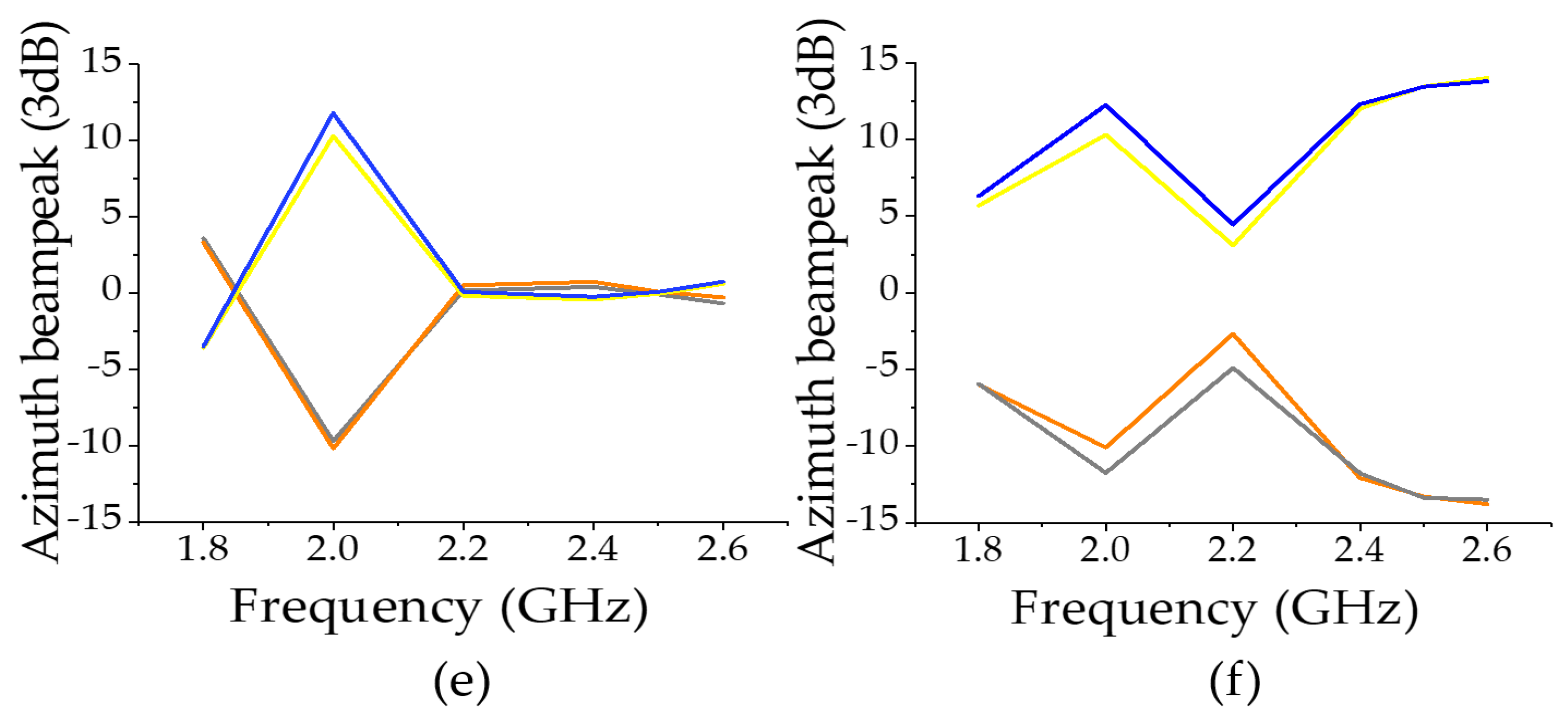
It is observed that the main beam shows a significant 3 dB and 10 dB beam squint with the slant dipoles compared to the LBHV, as shown in Figure 4a–f. The proposed work is also compared with the recent state-of-the-art works in Table 2, which shows isolation performances and the addition of structure type to radiating elements.

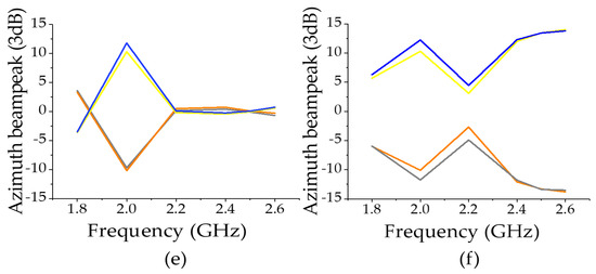
Figure 4.
Measured 10 dB azimuth beamwidth of HB arrays with (a) LBHV element (b) LB slant element, 10 dB azimuth beam peak of HB arrays with (c) LBHV element (d) LB slant element, 3 dB azimuth beam peak of HB arrays with (e) LBHV element (f) LB slant element. The P1, P2, P3, and P4 refer to polarizations indicated in Figure 1.

Table 2.
Comparison of recent state-of-the-art works with proposed work.
3. Virtual Slant Polarizations
The base station antennas require ±45 polarized antenna elements, and the proposed horizontal and vertical dipoles provide only horizontal and vertical polarization. Therefore, a novel technique creates a ±45 polarization virtually from H- and V-oriented dipoles. The 180° hybrid coupler is a common microwave component which can be realized either as a rat-race, ring or magic T-hybrid. The 180° hybrid coupler is commonly used to get in and out of phase signals. Different design approaches have been followed in the literature, just as in [15] where a specialized TL is designed for a compact rat race coupler.
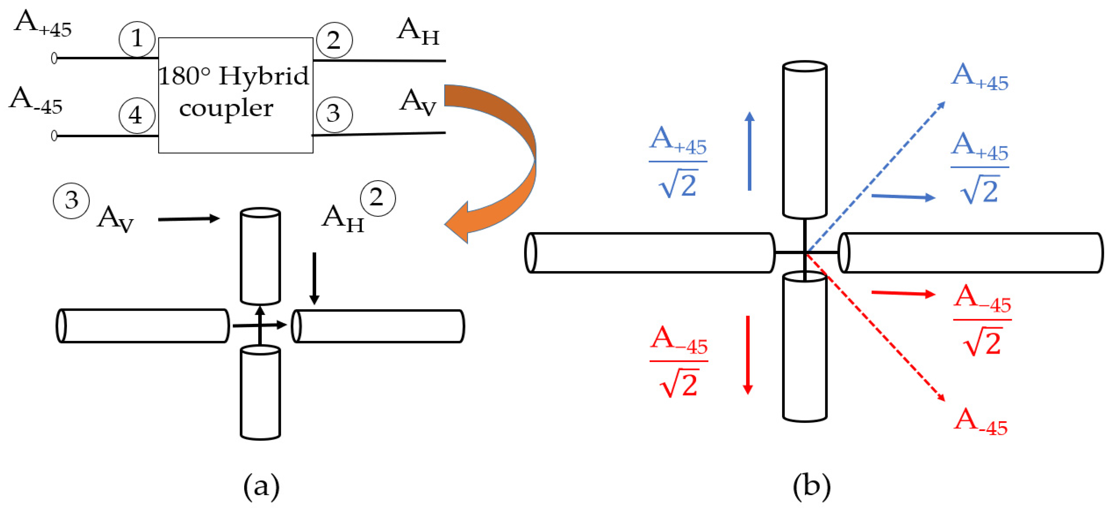
As shown in Figure 5a, a 180° hybrid coupler is used between the inputs and the LBHV element. Port 2 feeds the horizontal polarized element, and port 3 of the hybrid provides the vertically polarized dipole.
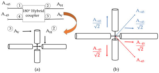
Figure 5.
(a) Conversion of slant-polarized inputs to H and V polarized inputs, (b) creation of virtual slant polarizations from H and V feed signals.
The AH and AV can be expressed in terms of the +45 and −45 input signals A+45 and A−45 as:
The output at port 2, fed to the horizontal-polarized dipole, contains the in-phase components of both the +45 and −45 polarizations, while the output port 3 contains signals of +45 in-phase and a −45 signal with a 180 phase shift. Since the +45 signal is fed in phase to both the H and V polarizations, it virtually creates a sum vector in the +45 direction, as shown in Figure 5b. The −45 component fed to the vertically polarized element has a 180° phase difference compared to the horizontally polarized dipole. Therefore, it creates a signal polarized in the −45 direction, as shown in Figure 5b. By the theory of reciprocity, the received signals at H and V dipoles provide the sum and difference signals, which are +45 and −45 signals, back to the baseband unit.
4. Low Band Element
The LBHV element should have a comparable performance in terms of patterns to a slant dipole, while providing minimum distortions to the HB patterns. The length of the dipoles in the H and V polarizations are optimized to meet these requirements. The optimized values were obtained through a series of parametric studies. It was found that the vertical dipole length presents more resonant behavior at the high band and needs to be shorter to reduce HB pattern distortions. This can result in a wider 3 dB beamwidth for LB patterns. A longer dipole close to a full wavelength is required in the H orientation to compensate for this.
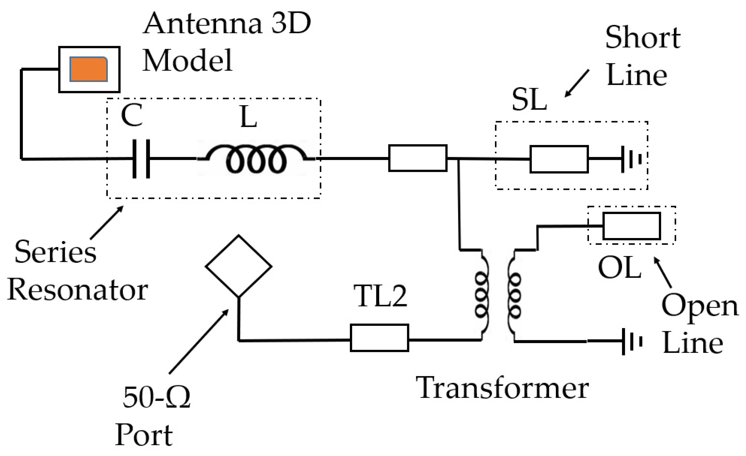
The LB dipoles need to be impedance-matched for the 690–960 MHz band. The impedance-matching network is based on a feed network design proposed in [16]. A ladder-type band-pass filter using a serial and shunt resonant LC circuit is used for wideband matching. As shown in Figure 6, a circuit model contains three tuners, i.e., a series resonator and a shunt resonator used to control/reduce the changing reactance, followed by a quasi-quarter wavelength transmission line (TL2). The optimization and physical realization were conducted in a CST studio to obtain the best match over the required band.
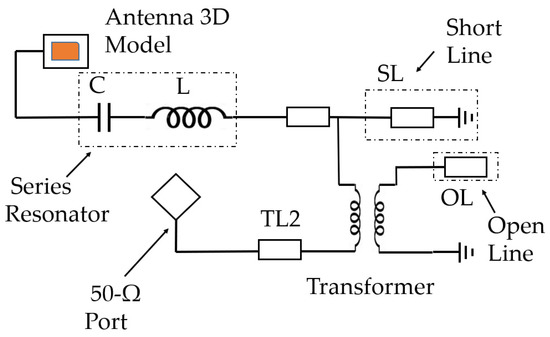
Figure 6.
Circuit theory model of matching circuit.
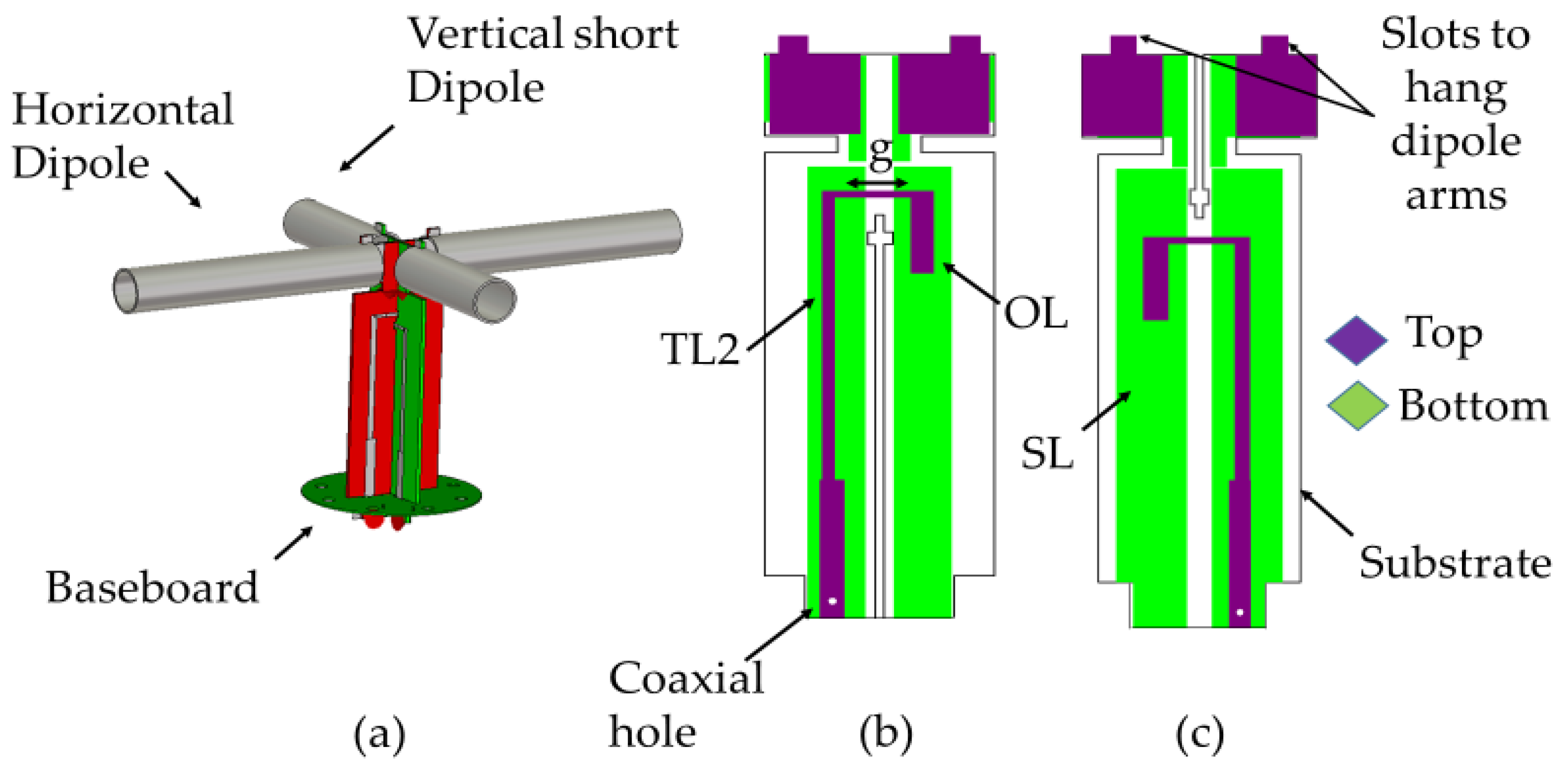
The matching circuit was implemented using microstrip technology, as shown in Figure 7a. The lines TL1 (transmission line) and SL (short line) are realized as coupled lines that are printed on the back-conducting layer, while TL2 and OL (open line) are conventional microstrip layers.
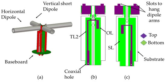
Figure 7.
(a) Perspective view of the LBHV. The horizontal dipole is 135 mm long, and the vertical dipole is 60 mm long, (b) details of the LB horizontal dipole (LBHD) feed, (c) details of the LB vertical dipole (LBVD) feed.
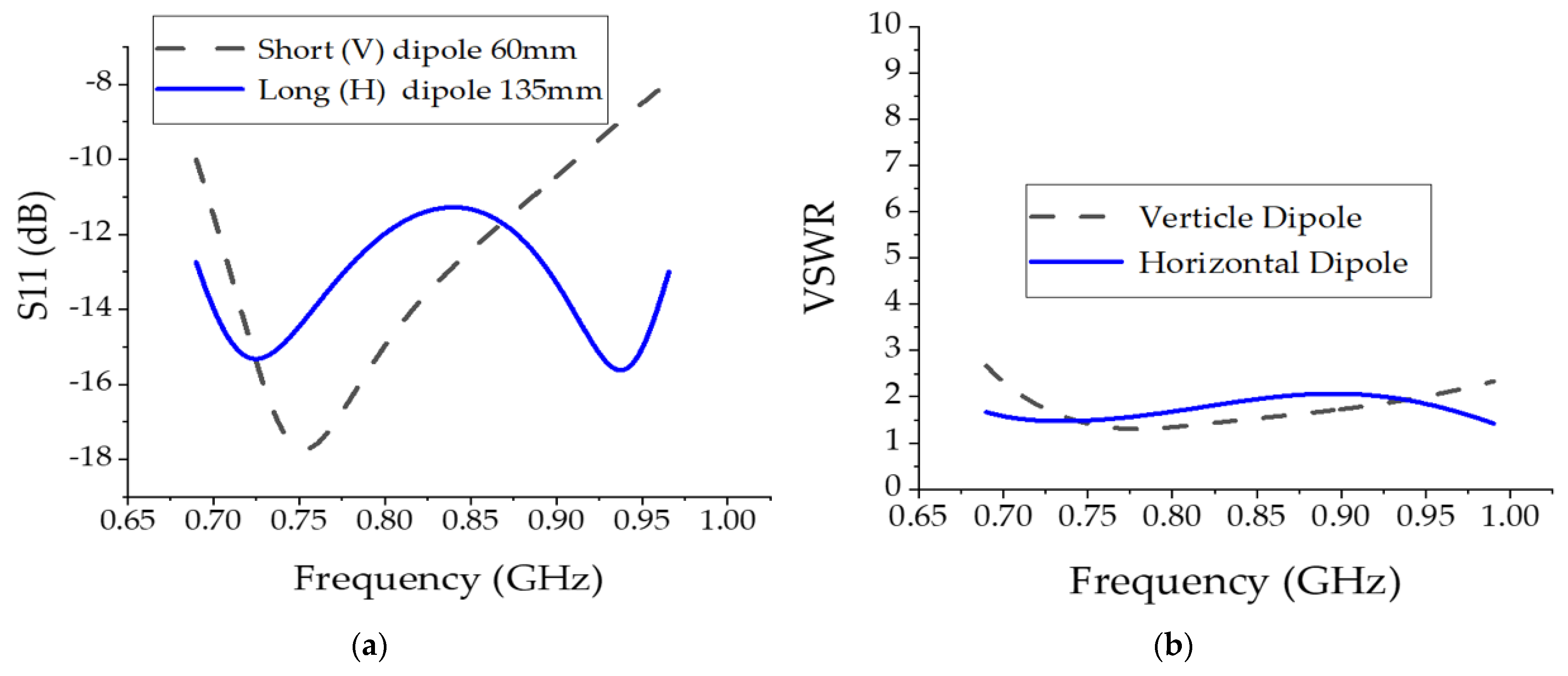
The configuration of horizontal dipole balun is shown in Figure 7b, while short dipole balun is depicted in Figure 7c. They are orthogonally arranged to feed the pair of horizontal and vertical LB arms. Although matching the short dipole is quite challenging, the antenna is well-matched with a reflection coefficient of better than 12 dB for horizontal polarization, and better than 10 dB for vertical polarization from 690 MHz to 960 MHz, as shown in Figure 8a. To have an insight into the working mechanism of the proposed antenna, VSWRs are studied and shown in Figure 8b. The optimized dimensions of the structure are those listed in Table 3. A fabricated prototype of the antenna is shown in Figure 9.
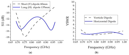
Figure 8.
(a) The measured return loss of the short V-dipole and long H-dipole. (b) VSWR of proposed antenna LBHV.

Table 3.
Optimized parameters of the proposed antenna.
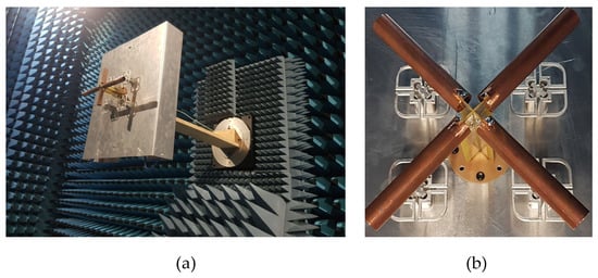
Figure 9.
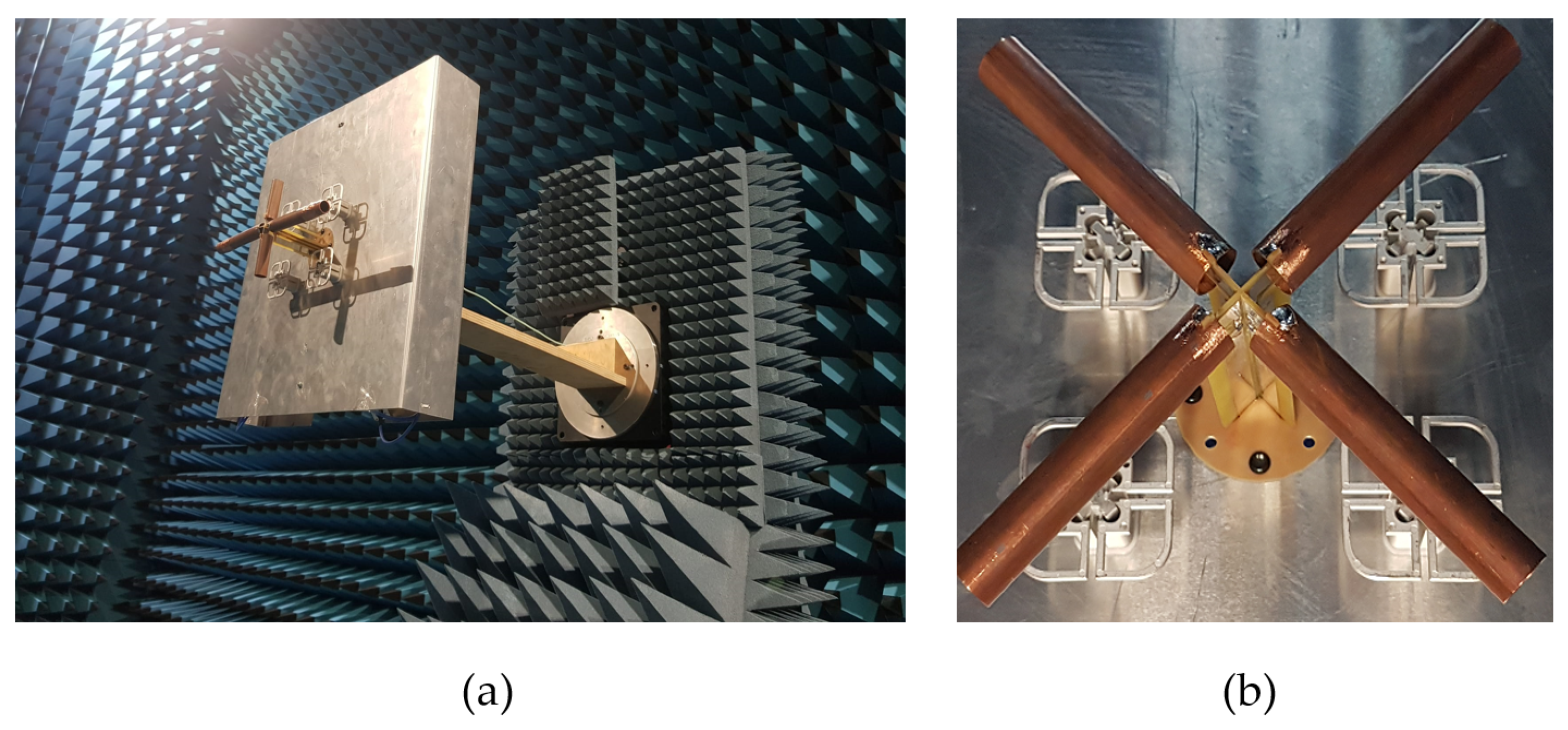
Fabricated prototype with (a) LBHV antenna element (b) LB slant element.
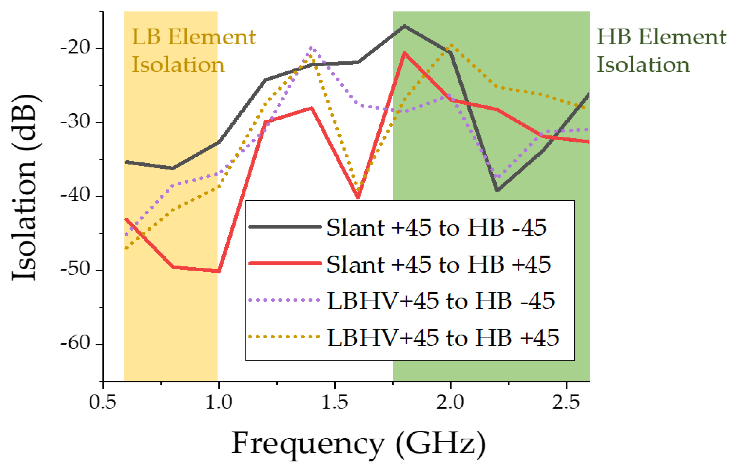
Despite this, the achieved HPBW with LBHV configuration is relatively stable, with a reflection coefficient larger than 12 dB. The port-to-port-measured worst-case isolation of LBHV configuration in hybrid mode is 36 dB at 960 MHz and 20 dB at 2 GHz, as shown in Figure 10, in the desired whole-band 690–960 MHz and 1810–2690 MHz, respectively.
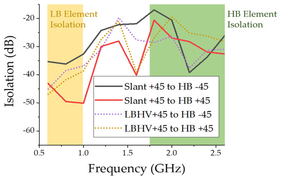
Figure 10.
Measured isolation of proposed antenna LBHV with slant.
5. Conclusions
The high band pattern distortions can be reduced by using a horizontal and vertical low band element instead of a conventional slant low band element. The scattering from this low band element is minimized since dipoles are moved away from the high band-radiating elements. This method is simpler compared to other techniques available in the literature that require significant modifications to radiating element design, resulting in an increased cost. The construction of the horizontal low band element is almost similar to a conventional low band element design, and therefore, construction and assembly are simple. The only addition is a 180° hybrid coupler, which is used to generate the slant polarizations. The new low band element is matched over the entire low band frequency range with >12 dB return loss and the low band patterns are identical to conventional slant low band element pattern with 6.2 dB gain, 60 ± 5° beam width for a single element.
Author Contributions
All authors conceived and proposed the idea; D.T. contribute towards structure of the paper. Wrote the paper under the supervision of D.T. All authors have read and agreed to the published version of the manuscript.
Funding
This research received no external funding.
Conflicts of Interest
The authors declare no conflict of interest.
References
- Osseiran, A.; Parkvall, S.; Persson, P.; Zaidi, A.; Magnusson, S.; Balachandran, K. 5G Wireless Access: An Overview; 1/28423-FGB1010937; Ericsson: Stockholm, Sweden, 2020. [Google Scholar]
- Kelly, I.; Zimmerman, M.; Butler, R.; Zheng, Y. Base Station Antenna Selection for LTE Networks. 2017. Available online: https://www.commscope.com/globalassets/digizuite/2096-bsa-selection-for-lte-networks-wp-108976.pdf?r=1 (accessed on 1 September 2022).
- Mandhyan, A. 4G and 5G Capacity Solutions-Comparative Study. 2019. Available online: https://telecoms.com/intelligence/4g-and-5g-capacity-solutions-comparative-study/ (accessed on 1 September 2022).
- Huang, H.; Liu, Y.; Gong, S. A Novel Dual-Broadband and Dual-Polarized Antenna for 2G/3G/LTE Base Stations. IEEE Trans. Antennas Propag. 2016, 64, 4113–4118. [Google Scholar] [CrossRef]
- Huang, H.; Liu, Y.; Gong, S. A Dual-Broadband, Dual-Polarized Base Station Antenna for 2G/3G/4G Applications. IEEE Antennas Wirel. Propag. Lett. 2017, 16, 1111–1114. [Google Scholar] [CrossRef]
- He, Y.; Pan, Z.; Cheng, X.; He, Y.; Qiao, J.; Tentzeris, M.M. A Novel Dual-Band, Dual-Polarized, Miniaturized and Low-Profile Base Station Antenna. IEEE Trans. Antennas Propag. 2015, 63, 5399–5408. [Google Scholar] [CrossRef]
- He, Y.; Tian, W.; Zhang, L. A novel dual-broadband dual-polarized electrical downtilt base station antenna for 2G/3G applications. IEEE Access 2017, 5, 15241–15249. [Google Scholar] [CrossRef]
- Elsherbini, A.; Wu, J.; Sarabandi, K. Dual Polarized Wideband Directional Coupled Sectorial Loop Antennas for Radar and Mobile Base-Station Applications. IEEE Trans. Antennas Propag. 2015, 63, 1505–1513. [Google Scholar] [CrossRef]
- Sun, H.H.; Ding, C.; Zhu, H.; Jones, B.; Guo, Y.J. Suppression of Cross-Band Scattering in Multiband Antenna Arrays. IEEE Trans. Antennas Propag. 2019, 67, 2379–2389. [Google Scholar] [CrossRef]
- Isik, O.; Gripo, P.; Thalakotuna, D.; Liversidge, P. Cloaked Low Band Elements for Multiband Radiating Arrays. US Patent 10 439 285 B2, 16 October 2019. [Google Scholar]
- Soric, J.C.; Monti, A.; Toscano, A.; Bilotti, F.; Alu, A. Dual-Polarized Reduction of Dipole Antenna Blockage Using Mantle Cloaks. IEEE Trans. Antennas Propag. 2015, 63, 4827–4834. [Google Scholar] [CrossRef]
- Zhang, Y.; Zhang, X.Y.; Ye, L.; Pan, Y. Dual-Band Base Station Array Using Filtering Antenna Elements for Mutual Coupling Suppression. IEEE Trans. Antennas Propag. 2016, 64, 3423–3430. [Google Scholar] [CrossRef]
- Zhao, L.; Wu, K. A Dual-Band Coupled Resonator Decoupling Network for Two Coupled Antennas. IEEE Trans. Antennas Propag. 2015, 63, 2843–2850. [Google Scholar] [CrossRef]
- Zhu, Y.; Chen, Y.; Yang, S. Decoupling and Low-Profile Design of Dual-Band Dual-Polarized Base Station Antennas Using Frequency-Selective Surface. IEEE Trans. Antennas Propag. 2019, 67, 5272–5281. [Google Scholar] [CrossRef]
- Lalbakhsh, A.; Mohamadpour, G.; Roshani, S.; Ami, M.; Roshani, S.; Sayem, A.S.M.; Alibakhshikenari, M.; Koziel, S. Design of a Compact Planar Transmission Line for Miniaturized Rat-Race Coupler With Harmonics Suppression. IEEE Access 2021, 9, 129207–129217. [Google Scholar] [CrossRef]
- Ding, C.; Sun, H.; Zhu, H.; Guo, Y. Achieving Wider Bandwidth with Full-Wavelength Dipoles for 5G Base Stations. IEEE Trans. Antenna Propag. 2020, 68, 1119–1127. [Google Scholar] [CrossRef]
Publisher’s Note: MDPI stays neutral with regard to jurisdictional claims in published maps and institutional affiliations. |
© 2022 by the authors. Licensee MDPI, Basel, Switzerland. This article is an open access article distributed under the terms and conditions of the Creative Commons Attribution (CC BY) license (https://creativecommons.org/licenses/by/4.0/).

