A Procedure to Design Feasible Dual Band Matching Networks with Minimum Complexity
Abstract
:1. Introduction
2. Matching Procedure
2.1. Third Line Elements
3. Numerical Results and Experimental
4. Conclusions
Author Contributions
Funding
Data Availability Statement
Conflicts of Interest
References
- Paredes, F.; Gonzalez, G.; Bonache, J.; Martín, F. Dual-Band Impedance-Matching Networks Based on Split-Ring Resonators for Applications in RF Identification (RFID). IEEE Trans. Microw. Theory Tech. 2010, 58, 1159–1166. [Google Scholar] [CrossRef]
- Gu, X.; Srinaga, N.N.; Guo, L.; Hemour, S.; Wu, K. Diplexer-Based Fully Passive Harmonic Transponder for Sub-6-GHz 5G-Compatible IoT Applications. IEEE Trans. Microw. Theory Tech. 2019, 67, 1675–1687. [Google Scholar] [CrossRef]
- Meng, X.; Yu, C.; Wu, Y.; Liu, Y. Design of Dual-Band High Efficiency Power Amplifiers Based on Compact Broadband Matching Networks. IEEE Microw. Wirel. Compon. Lett. 2018, 28, 162–164. [Google Scholar] [CrossRef]
- Wu, L.; Sun, Z.; Yilmaz, H.; Berroth, M. A dual-frequency wilkinson power divider. IEEE Trans. 2006, 54, 278–284. [Google Scholar] [CrossRef]
- Chow, Y.L.; Wan, K.L. A transformer of one-third wavelength in two sections-for a frequency and its first harmonic. IEEE Microw. Wireless Compon. Lett. 2002, 12, 22–23. [Google Scholar] [CrossRef]
- Monzon, C. Analytical derivation of a two-section impedance transformer for a frequency and it first harmonic. IEEE Microw. Wireless Compon. Lett. 2002, 12, 381–382. [Google Scholar] [CrossRef]
- Monzon, C. A small dual-frequency transformer in two sections. IEEE Trans. Microw. Theory Tech. 2003, 51, 1157–1161. [Google Scholar] [CrossRef]
- Orfanidis, S.J. A two-section dual-band Chebyshev impedance transformer. IEEE Microw. Wirel. Compon. Lett. 2003, 13, 382–384. [Google Scholar] [CrossRef]
- Castaldi, G.; Fiumara, V.; Gallina, I. An exact synthesis method for dual-band Chebyshev impedance transformers. Prog. Electromagn. Res. 2008, 86, 305–319. [Google Scholar] [CrossRef] [Green Version]
- Park, M.; Lee, B. Dual-band design of sing-stub impedance matching networks with application to dual-band stubbed T-junctions. Microw. Opt. Technol. Lett. 2010, 52, 1359–1362. [Google Scholar] [CrossRef]
- Liu, L.; Geng, J.; Liu, F.; Fan, H.; Liang, X.; Wang, W.; Jin, R. A Novel Analytical Method for Multi-Frequency Transmission Line Transformer. IEEE Microw. Wirel. Compon. Lett. 2016, 26, 556–558. [Google Scholar] [CrossRef]
- Wu, Y.; Liu, Y.; Li, S. A compact Pi-structure dual band transformer. Prog. Electromagn. Res. 2008, 88, 121–134. [Google Scholar] [CrossRef] [Green Version]
- Colantonio, P.; Giannini, F.; Scucchia, L. A new approach to design matching networks with distributed elements. In Proceedings of the MIKON’04, Poland, Warsaw, 17–19 May 2004; Volume 3, pp. 811–814. [Google Scholar]
- Wu, Y.; Liu, Y.; Li, S.; Yu, C.; Liu, X. A generalized dual-frequency transformer for two arbitrary complex frequency-dependent impedances. IEEE Microw. Wirel. Compon. Lett. 2009, 19, 792–794. [Google Scholar] [CrossRef]
- Wu, Y.L.; Liu, Y.A.; Li, S.L. A dual-frequency transformer for complex impedances with two unequal sections. IEEE Microw. Wirel. Compon. Lett. 2009, 19, 77–79. [Google Scholar] [CrossRef]
- Liu, X.; Liu, Y.A.; Li, S.L.; Wu, F.; Wu, Y.L. A three-section dual band transformer for frequency-dependent complex load impedance. IEEE Microw. Wirel. Compon. Lett. 2009, 19, 611–613. [Google Scholar] [CrossRef]
- Sinha, R. Comments on A Three-Section Dual-Band Transformer for Frequency-Dependent Complex Load Impedance. IEEE Microw. Wirel. Compon. Lett. 2019, 29, 783–785. [Google Scholar] [CrossRef]
- Nikravan, M.A.; Atlasbaf, Z. T-section dual-band impedance transformer for frequency-dependent complex loads. Electron. Lett. 2011, 47, 551–553. [Google Scholar] [CrossRef]
- Chuang, M.-L. Dual-band impedance transformer using two-section shunt stubs. IEEE Trans. Microw. Theory Tech. 2010, 58, 1257–1263. [Google Scholar] [CrossRef]
- Manoochehri, O.; Asoodeh, A.; Forooraghi, K. Pi-model dual-band impedance transformer for unequal complex impedance loads. IEEE Microw. Wirel. Compon. Lett. 2015, 25, 238–240. [Google Scholar]
- Zheng, X.; Liu, Y.; Li, S.; Yu, C.; Wang, Z.; Li, J. A Dual-Band Impedance Transformer Using Pi-Section Structure for Frequency-Dependent Complex Loads. Prog. Electromagn. Res. C 2012, 32, 11–26. [Google Scholar]
- Saxena, A.; Banerjee, D.; Gupta, R.; Hashmi, M. Design of πStructure Dual-Band Matching Network With Unequal Susceptance Cancellation Stubs. In Proceedings of the 2018 IEEE MTT-S International Microwave and RF Conference (IMaRC), Kolkata, India, 28–30 November 2018; pp. 1–3. [Google Scholar]
- Saxena, A.; Banerjee, D.; Hashmi, M.; Auyenur, M. A Dual-Band Impedance Transfomer for Matching Frequency Dependent Complex Source and Load Impedances. In Proceedings of the 2019 15th Conference on Ph.D Research in Microelectronics and Electronics (PRIME), Lausanne, Switzerland, 15–18 July 2019; pp. 173–176. [Google Scholar]
- Yazdani, F.; Mansour, R.R. Realization of Dual-Band Matching Networks Using Cascaded Filters. In Proceedings of the 2020 50th European Microwave Conference (EuMC), Utrecht, The Netherlands, 12–14 January 2021; pp. 727–730. [Google Scholar]
- Maktoomi, M.A.; Hashmi, M.S.; Ghannouchi, F.M. Improving Load Range of Dual-Band Impedance Matching Networks Using Load-Healing Concept. IEEE Trans. Circuits Syst. II Express Briefs 2017, 64, 126–130. [Google Scholar] [CrossRef]
- Chuang, M.-L.; Wu, M.-T. General Dual-Band Impedance Transformer With a Selectable Transmission Zero. IEEE Trans. Compon. Packag. Manuf. Technol. 2016, 6, 1113–1119. [Google Scholar] [CrossRef]
- Pozar, D.M. Microwave Engineering; John Wiley & Sons: Hoboken, NJ, USA, 2009. [Google Scholar]
- Matlab. Available online: https://www.mathworks.com/ (accessed on 27 October 2022).
- AWR Software. Available online: https://www.awr.com/ (accessed on 27 October 2022).
- Gupta, K.C.; Garg, R.; Bahl, I.J.; Barthia, P. Microstrip Lines and Slotlines, 2nd ed.; Artech House: Norwood, MA, USA, 1996. [Google Scholar]
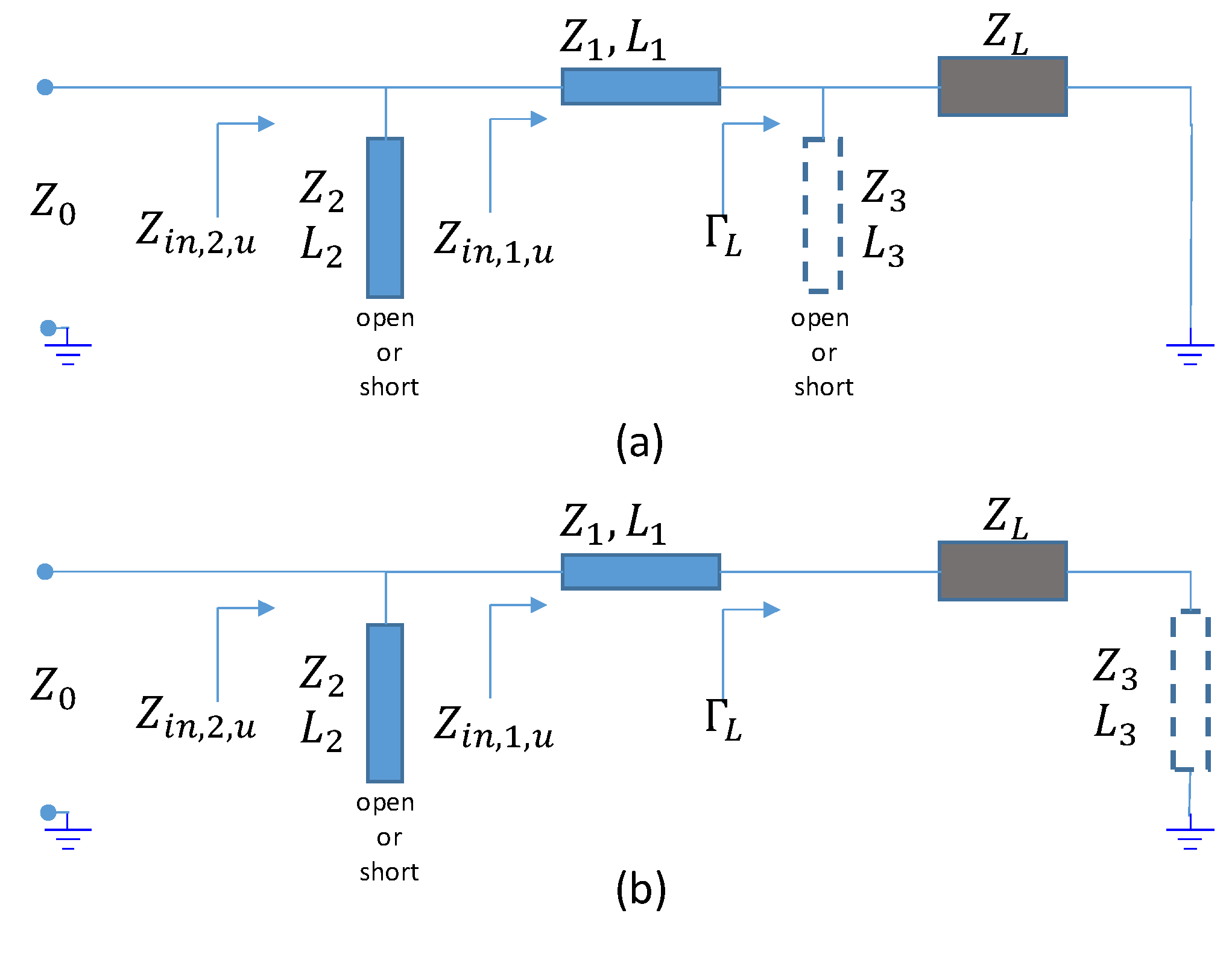
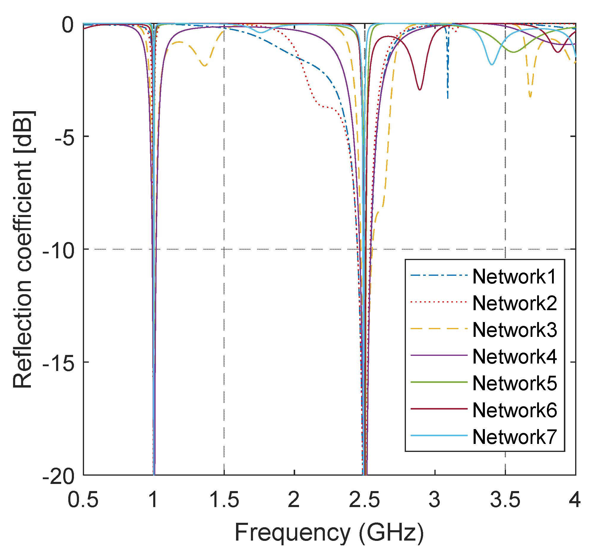
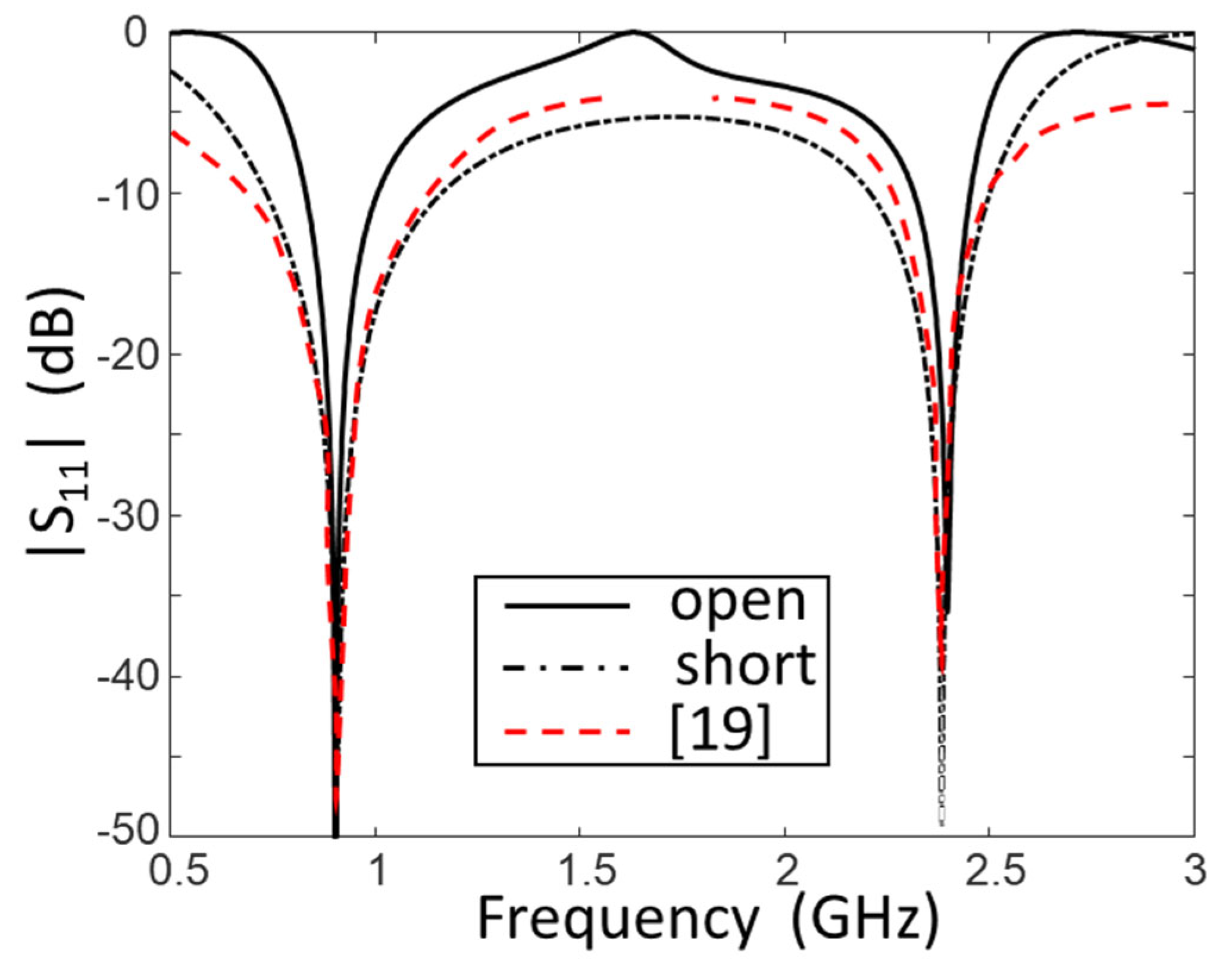

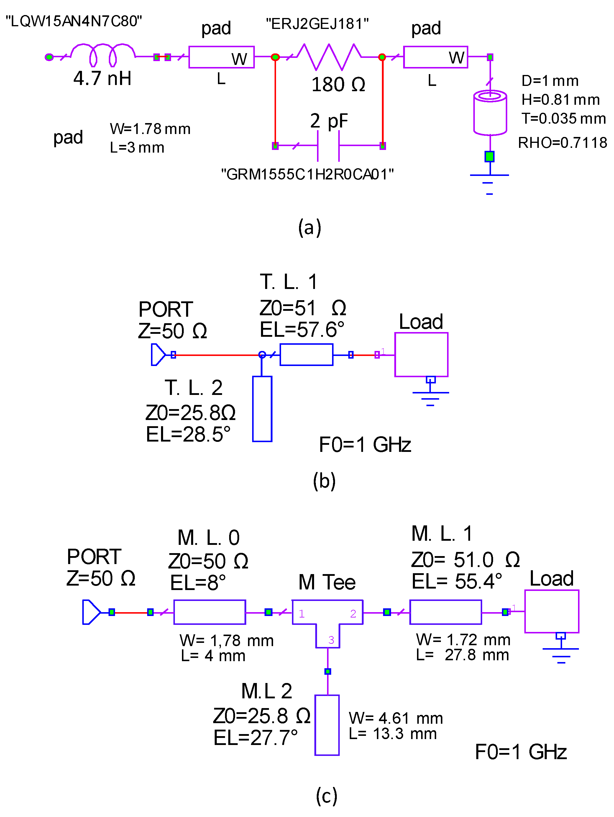
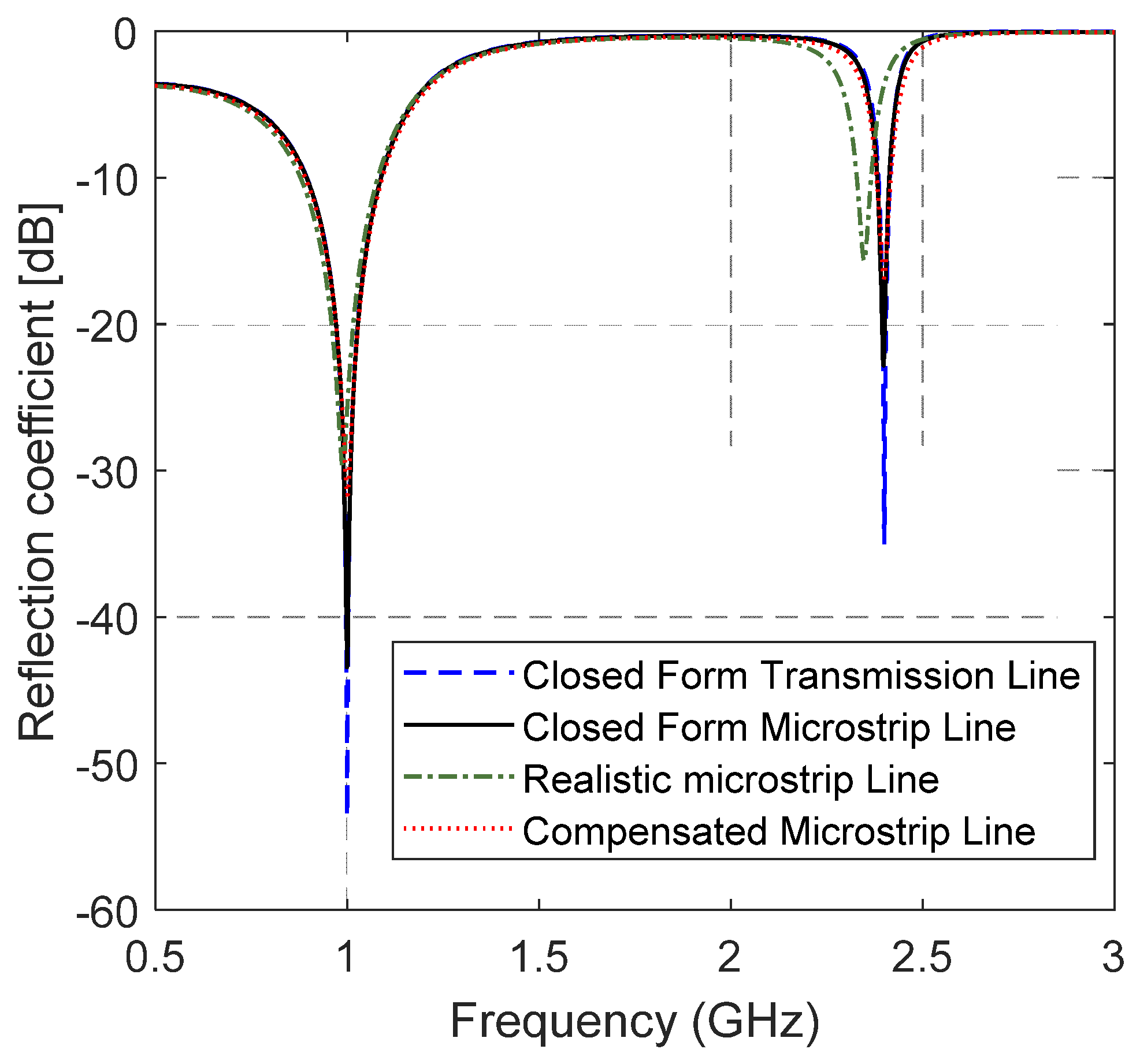
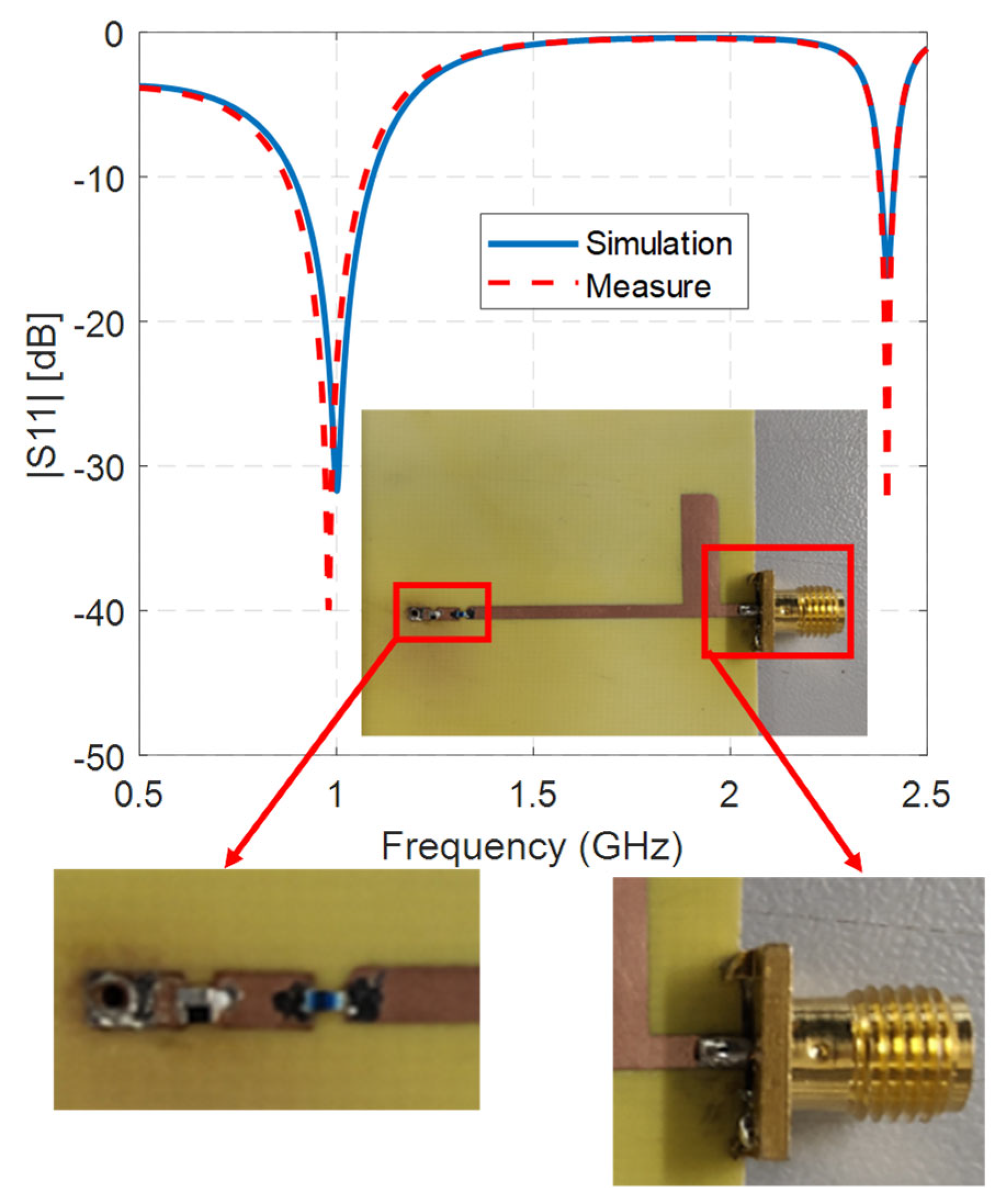
| 52 − j456 28 − j180 | 1.0 2.5 | 43.8/90.9 | 75.7/86 (o) | 70/27.5 (l) |
| 22.5/76.7 (o) | ||||
| 124.7/67.3 | 13.2/139 (o) | |||
| 34/24 (s) | ||||
| 35.1/48.2 | 18.6/99.6 (o) | 70/53.1 (o) | ||
| 56.7/43.8 | 11.7/160.8 (s) | |||
| 21.5/112.7 | 12.2/99.9 (o) | 70/27.7 (s) | ||
| 22 − j 403 16 − j 386 | 0.867 0.920 | 15.7/74.2 | 40.8 (o)/94.2 | 40/80 (l) |
| 34.2/89.7 | 110.5 (s)/176.7 | |||
| 22.5 − j22 5 + j66.5 | 1.0 2.4 | 51/57.6 | 25.8/28.5 (o) | n.n. |
| 72.2/146.6 (s) | ||||
| 57.6/50.3 | 44/43.1 (o) | |||
| 91.2/152.8 (s) | ||||
| 25/115.8 | 49/40.2 (o) | |||
| 105.8/151.3 (s) | ||||
| 22.2/125.7 | 44/34.6 (o) | |||
| 105.3/148.8 (s) | ||||
| [14] a 400 + j30 400 + j30 | 1 2 | 80/122.4 | 40/119 (o) | 50/58.5 (s) |
| 13.5/59 (s) | ||||
| [14] b 400 + j40 400 + j40 | 1 3.5 | 120/80.8 | 32/160 (o) | n.n. |
| [19] a 200 + j60 250 + j100 | 2.4 5.8 | 100/109 | 36/102 (s) | n.n. |
| [19] b 100 − j 35.4 150 − j6.4 | 0.9 2.4 | 44/45.2 | 37.7/51.2 (s) | n.n. |
| 27.9/149.2 (o) | ||||
| [20] 10 − j66.3 10 − j44.2 | 2.4 3.6 | 78.3/28.7 | 14.4/142.3 (o) | n.n. |
| [22] a 100 + j80 150 + j100 | 1 1.8 | 33.4/68.5 | 27.3/130.5 (o) 11/65.9 (s) | n.n. |
| [22] b 50 + j80 60 + j 120 | 1 1.8 | 15/66.4 | 11/131.9 (o) | n.n. |
| [22] c 100 + j0 120 + j0 | 1 2 | 44/52 | 40/54.7 (s) | n.n. |
| 20.4/160.1 (o) | ||||
| 68.6/103.6 | 59.6/101.9 (s) | |||
| [25] a 92.8 − j15.8 78.8 − j21.5 | 1 2 | 57.5/50.8 | 64.1/58.5 (s) | n.n. |
| 57.6/111.1 | 64.4/121.5 (s) | |||
| [25] b 10.3 − j11.9 11.1 + j24.4 | 1 2 | 21.8/85.6 | 20.5/66.4 (s) | n.n. |
| 65.5/125.7 (o) | ||||
| [25] c 155.9 − j27 130.4 − j54.8 | 1 2.5 | 84.8/95.5 | 54.2/108 (s) | n.n. |
| 37.4/102.6 (s) | ||||
| [25] d 86.5 + j13.4 90.1 + j21.4 | 1.5 2.5 | 29.6/138.8 | 36.2/134 (s) | n.n. |
| 87.5/66.8 (o) | ||||
| 61.8/77.9 | 64.3/69.6 (s) | |||
| [26] 101 − j35.4 101 − j15.2 | 0.9 2.1 | 59.6/47.5 | 62.4/52.2 (s) | n.n. |
| 27.8/160.9 (o) | ||||
| 62.5/101.3 | 31.7/109.3 (s) |
Publisher’s Note: MDPI stays neutral with regard to jurisdictional claims in published maps and institutional affiliations. |
© 2022 by the authors. Licensee MDPI, Basel, Switzerland. This article is an open access article distributed under the terms and conditions of the Creative Commons Attribution (CC BY) license (https://creativecommons.org/licenses/by/4.0/).
Share and Cite
DiCarlofelice, A.; DiGiampaolo, E.; Tognolatti, P. A Procedure to Design Feasible Dual Band Matching Networks with Minimum Complexity. Electronics 2022, 11, 3569. https://doi.org/10.3390/electronics11213569
DiCarlofelice A, DiGiampaolo E, Tognolatti P. A Procedure to Design Feasible Dual Band Matching Networks with Minimum Complexity. Electronics. 2022; 11(21):3569. https://doi.org/10.3390/electronics11213569
Chicago/Turabian StyleDiCarlofelice, Alessandro, Emidio DiGiampaolo, and Piero Tognolatti. 2022. "A Procedure to Design Feasible Dual Band Matching Networks with Minimum Complexity" Electronics 11, no. 21: 3569. https://doi.org/10.3390/electronics11213569
APA StyleDiCarlofelice, A., DiGiampaolo, E., & Tognolatti, P. (2022). A Procedure to Design Feasible Dual Band Matching Networks with Minimum Complexity. Electronics, 11(21), 3569. https://doi.org/10.3390/electronics11213569


