
A Video-Based Real-Time Tracking Method for Multiple UAVs in Foggy Weather

Abstract
:1. Introduction
2. Image Defogging Algorithm Based on Improved Dark Channel
2.1. Determination of Transmissivity by Mean Filtering
2.2. Estimation of Global Atmospheric Light Value
3. Tracking of Multiple UAVs with Improved YOLOv5 and Deepsort
3.1. Optimization and Improvement of YOLOv5 Network
3.1.1. Removal of Focus Layer
3.1.2. Backbone Optimization Based on ShuffleNet V2
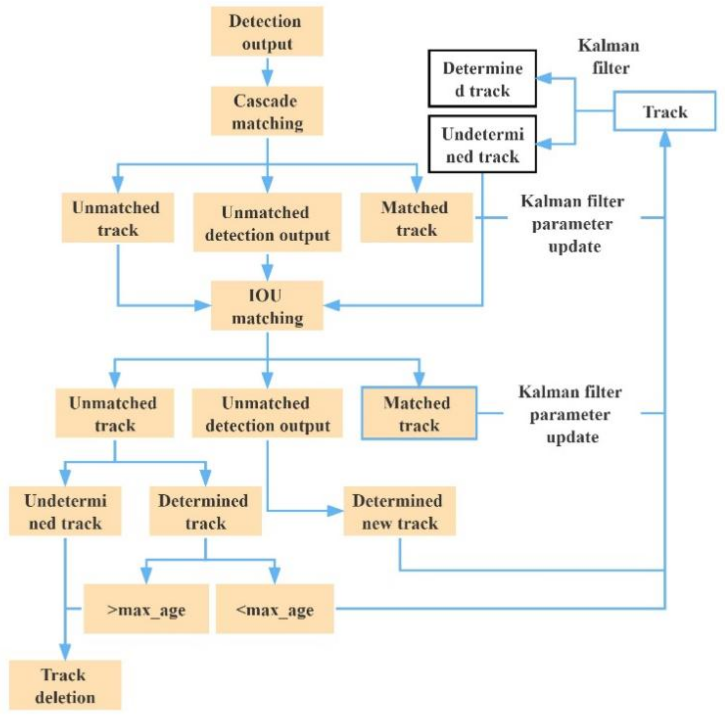
3.2. Tracking of Multiple UAVs Based on Deepsort
4. Image Compression
5. Experiment Design and Result Analysis
5.1. Preparation for Experiments
5.2. Comparison of Algorithm Improvement Effects
5.2.1. Comparison of YOLOv5 Network Improvement Effect
5.2.2. Multi-UAV Target Tracking Experiments on UAVs under Normal Illumination
- (1)
- For multiple UAV targets in stable flight state, YOLOv5 + Deepsort algorithm and improved YOLOv5 + Deepsort algorithm had stable tracking abilities.
- (2)
- For multiple UAV targets with mutual occlusion, when the targets were separated, the algorithm could still track the target and keep the original target ID unchanged without the problem of target ID matching error.
- (3)
- For small scale targets and scale changing targets, the algorithm could also accurately identify and track them. In the process of tracking multiple UAV targets, as long as the flying targets did not exceed the video capture range, no IDs were generated for the algorithm.
- (4)
- Moreover, the improved YOLOv5 algorithm could significantly improve the tracking speed. The average tracking frame rate of the original tracking algorithm was 15 FPS, and the tracking effect could not meet the real-time tracking requirements. By reducing the complexity of the original network, YOLOv5 greatly reduced the detection time in the tracking process. The average tracking frame rate reached 43 FPS, far exceeding the real-time tracking performance requirements. Real-time and high-precision tracking of multiple UAV targets was realized.


| Tracking Method | MOTA↑ | MOTP↓ | IDs↓ | FPS |
|---|---|---|---|---|
| YOLOv5 + Deepsort | 97.20% | 0.241 | 2 | 15 |
| Improved YOLOv5 + Deepsort | 99.40% | 0.227 | 2 | 43 |
5.3. Target Tracking Experiment of UAV under Fog Interference
5.3.1. Comparison of Detection Results with Different Defogging Algorithms
5.3.2. Comparison of Target Tracking Results of Multiple UAVs under Fog Interference
- (1)
- Defogging could effectively improve the effects of multiobject tracking. In the experimental results of Method 1, the target detection for UAV failed due to fog interference, the tracking accuracy was only 52.8%, and the discontinuity of tracks led to the error of target ID matching and the generation of IDs. Generally, Method 4 achieved the best tracking indexes. It improved MOTA by 35.2% and MOTP by 31.7% compared to Method 1.
- (2)
- Defogging increased the time of processing a single frame of the image. With Method 2, the time extended by 603.4% after defogging. It decreased by 54.7% compared to Method 4 after improving the dark channel and optimizing the YOLOv5 network structure, but it was still 218.6% higher than Method 1.
5.3.3. Real-Time Tracking with Compressed Images
- (1)
- The smaller the compression size of images without distortion, the shorter the average defogging time and the shorter the tracking time per frame. However, when the size was too small, it led to a dramatic decrease in the tracking effect. When the size was further compressed, the size of the UAV target in the image was too small to highlight its feature information, so the tracking accuracy decreased and the discontinuity of tracking led to ID matching errors.
- (2)
- Within a certain range of compression size without distortion, the accuracy of object tracking could exceed 85% in all cases. When the images were compressed to 576 × 324, the tracking time per frame was 0.036 s, and the accuracy of object tracking was 88.9%. Therefore, the requirements for accuracy and real-time processing were satisfied simultaneously.
- (3)
- After the compression size of 576 × 324, Method 4 achieved a 36.1% higher tracking precision and 39% higher tracking speed than Method 1 in the tracking of multiple UAVs.
6. Conclusions
Author Contributions
Funding
Institutional Review Board Statement
Informed Consent Statement
Data Availability Statement
Conflicts of Interest
References
- Jiang, L.; Yang, J. Detection Optimized Labeled Multi-Bernoulli Algorithm for Visual Multi-Target Tracking. J. Front. Comput. Sci. Technol. 2022, 1–20. [Google Scholar]
- Leal-Taixé, L.; Canton-Ferrer, C.; Schindler, K. Learning by Tracking: Siamese CNN for Robust Target Association. In Proceedings of the 2016 IEEE Conference on Computer Vision and Pattern Recognition Workshops (CVPRW), Las Vegas, NV, USA, 26 June–1 July 2016; IEEE Press: New York, NY, USA, 2016; pp. 418–425. [Google Scholar]
- Jiamin, R.; Ningsheng, G.; Zhenyang, H. Multi-target tracking algorithm based on YOLOv3 and Kalman Filter. Comput. Appl. Softw. 2020, 37, 169–176. [Google Scholar]
- Salazar-Colores, E.U.S.; Moya-Sánchez, J.-M.; Ramos-Arreguín, E.; Cabal-Yépez, G.F.; Cortés, U. Fast Single Image Defogging with Robust Sky Detection. IEEE Access 2020, 8, 149176–149189. [Google Scholar] [CrossRef]
- Liu, M.; Cheng, X.; Diao, C.; Chen, S. Object tracking algorithm based on kernelized correlation filter with dark channel defogging. J. Tianjin Univ. Technol. 2019, 35, 27339–27351. [Google Scholar]
- Hongwei, W.; Jie, T.; Zhuopeng, X. A review of image defogging algorithms. Softw. Guide 2021, 20, 231–235. [Google Scholar]
- Chen, J.; Xu, B. Research on machine vision image clearness under fog and haze weather conditions. Comput. Eng. 2017, 43, 280–285. [Google Scholar]
- Chen, Z. Homomorphic filtering defogging of buoy images based on convolutional neural network. Navig. China 2020, 43, 84–88. [Google Scholar]
- He, H.; Turghunjian, ·A.; He, X. A method of colored image defogging based on wavelet transform. Comput. Technol. Dev. 2020, 30, 60–64. [Google Scholar]
- Wang, R.G.; Zhu, J.; Yang, W.T.; Fang, S.; Zhang, X.T. An improved local multi-scale Retinex algorithm based on illuminance image segmentation. Acta Electron. Sin. 2010, 38, 1181–1186. [Google Scholar]
- Guo, L.; Song, J.; Li, X.; Huang, H.; Du, J.; Sheng, G. Single image haze removal using dark channel prior and adaptive transmission rate. In Proceedings of the 2018 2nd International Conference on Computer Science and Intelligent Communication(CSIC 2018), Xi’an, China, 16–17 August 2018. [Google Scholar]
- Raanan, F. Dehazing using color-lines. ACM Trans. Graph. 2014, 34, 13. [Google Scholar]
- Peng, L.; Jing, L.; Rui, Z. Research and implementation of single image fast dehazing algorithm. China Comput. Commun. 2019, 31, 43–44. [Google Scholar]
- Ma, R.; Zhang, S. An improved color image defogging algorithm using dark channel model and enhancing saturation. Opt. Int. J. Light Electron Opt. 2019, 180, 997–1000. [Google Scholar] [CrossRef]
- Zhang, X.; Ji, J.; Wang, L.; He, Z.; Liu, S. People’s Fast Moving Detection Method in Buses Based on YOLOv5. Int. J. Sens. Sens. Netw. 2021, 9, 30. [Google Scholar]
- Zhang, L.; Zhang, L.; Jiang, J.; Fang, W.; Liu, K. RealTime Detection and Tracking Method of Pilot’s Head Position Based on MTCNN-DeepSORT. J. Phys. Conf. Ser. 2020, 1682, 012025. [Google Scholar] [CrossRef]
- Qiu, X.; Sun, X.; Chen, Y.; Wang, X. Pedestrian Detection and Counting Method based on YOLOv5+DeepSORT; Tibet University: Lhasa, China, 2021. [Google Scholar]
- Pu, H.; Li, Z.; Li, L. Research of image dehazing based on dark channel prior. Laser Optoelectron. Prog. 2021, 58, 175–181. [Google Scholar]
- Qing, T.; Tongyang, Y.; Dan, Y.; Yun, W. A pedestrian detection method based on dark channel defogging and deep learning. Laser Optoelectron. Prog. 2018, 634, 187–195. [Google Scholar]
- He, K.M.; Sun, J.; Tang, X. Single image haze removal using dark channel prior. IEEE Trans. Pattern Anal. Mach. Intell. 2011, 33, 2341–2353. [Google Scholar]
- Yin, J.; Qu, S.; Yao, Z.; Hu, X.; Qin, X.; Hua, P. Traffic sign recognition model in haze weather based on YOLOv5. J. Comput. Appl. 2022, 42, 2876. [Google Scholar]
- YOLOV5 Object Detection-OSA-BottleneckCSP. Available online: https://zhuanlan.zhihu.com/p/462034609 (accessed on 18 March 2020).
- Ma, N.; Zhang, X.; Zheng, H.T.; Sun, J. ShuffleNet V2: Practical Guidelines for Efficient CNN Architecture Design. In , Proceedings of the European Conference on Computer Vision, Munich, Germany, 8–14 September 2018; Springer: Cham, Switzerland, 2018. [Google Scholar]
- Jin, L.; Hua, Q.; Guo, B.; Xie, X.; Yan, F.; Wu, B. Multi-target tracking of vehicles based on optimized DeepSort. J. Zhejiang Univ. Eng. Sci. 2021, 55, 1056–1064. [Google Scholar]
- Song, S.; Zhan, Y.; Li, G. Hyperspectral Image Compression Employing Target Detection. Comput. Technol. Dev. 2009, 19, 1–3+158. [Google Scholar]
- Sun, Z. Research on Lossless Compression and Dehazing Algorithm in Front Precess System of Camera; Shan Dong University: Jinan, China, 2018. [Google Scholar]
- Huang, Y.; Liao, X.; Lu, Q. Infrared images interpolation algorithm combining bilinear interpolation and local mean. Comput. Technol. Autom. 2020, 39, 133–137. [Google Scholar] [CrossRef]
- Ma, J.; Yao, Z.; Xu, C.; Chen, S. Multiple drones real-time tracking algorithm based on improved PP-YOLO and Deep-SORT. J. Comput. Appl. 2022, 42, 2885. [Google Scholar]


| 1: Input foggy image . |
| 2: Obtain a dark channel image. |
| 3: Average filtering of M (x). |
| 4: Calculate the mean value of all elements in to obtain . |
| 5: Calculate the global atmospheric light value. |
| 6: Calculate transmittance . |
| 7: Output: calculate the defogging image. |
| Model | FLOPs | Parameters | Model Size | Reference Time | AP0.5 | AP0.5:0.95 |
|---|---|---|---|---|---|---|
| YOLOv5 | 16.3 G | 7,053,910 | 13.7 M | 27.9 ms | 0.977 | 0.465 |
| Improved YOLOv5 | 2.6 G | 719,926 | 1.58 M | 14.2 ms | 0.99 | 0.503 |
| Category | Index | |||
|---|---|---|---|---|
| Precision | Recall | AP0.5 | AP0.5:0.95 | |
| Foggy image | 0.739 | 0.87 | 0.876 | 0.381 |
| Multiscale Retinex defogging | 0.532 | 0.502 | 0.503 | 0.194 |
| AHE defogging | 0.757 | 0.829 | 0.87 | 0.375 |
| CLAHE defogging | 0.882 | 0.904 | 0.944 | 0.451 |
| Dark channel defogging | 0.894 | 0.813 | 0.928 | 0.49 |
| Improved dark channel defogging | 0.917 | 0.935 | 0.979 | 0.503 |
| Defogging and Tracking Method | MOTA↑ | MOTP↓ | IDs↓ | Tracking Time per Frame/s |
|---|---|---|---|---|
| Method 1 | 52.8% | 0.315 | 1 | 0.059 |
| Method 2 | 64.5% | 0.322 | 0 | 0.415 |
| Method 3 | 77.1% | 0.263 | 0 | 0.230 |
| Method 4 | 87.0% | 0.215 | 0 | 0.188 |
| Compression Size | MOTA↑ | MOTP↓ | IDs↓ | Tracking Time per Frame/s |
|---|---|---|---|---|
| 1920 × 1080 | 87.0% | 0.215 | 0 | 0.188 |
| 960 × 540 | 88.3% | 0.216 | 0 | 0.067 |
| 768 × 432 | 87.2% | 0.218 | 0 | 0.047 |
| 576 × 324 | 88.9% | 0.225 | 0 | 0.036 |
| 384 × 216 | 85.5% | 0.242 | 0 | 0.029 |
| 192 × 108 | 51.5% | 0.341 | 14 | 0.023 |
Publisher’s Note: MDPI stays neutral with regard to jurisdictional claims in published maps and institutional affiliations. |
© 2022 by the authors. Licensee MDPI, Basel, Switzerland. This article is an open access article distributed under the terms and conditions of the Creative Commons Attribution (CC BY) license (https://creativecommons.org/licenses/by/4.0/).
Share and Cite
Dai, J.; Wu, L.; Wang, P. A Video-Based Real-Time Tracking Method for Multiple UAVs in Foggy Weather. Electronics 2022, 11, 3576. https://doi.org/10.3390/electronics11213576
Dai J, Wu L, Wang P. A Video-Based Real-Time Tracking Method for Multiple UAVs in Foggy Weather. Electronics. 2022; 11(21):3576. https://doi.org/10.3390/electronics11213576
Chicago/Turabian StyleDai, Jiashuai, Ling Wu, and Pikun Wang. 2022. "A Video-Based Real-Time Tracking Method for Multiple UAVs in Foggy Weather" Electronics 11, no. 21: 3576. https://doi.org/10.3390/electronics11213576
APA StyleDai, J., Wu, L., & Wang, P. (2022). A Video-Based Real-Time Tracking Method for Multiple UAVs in Foggy Weather. Electronics, 11(21), 3576. https://doi.org/10.3390/electronics11213576