Article

Degradation Prediction of GaN HEMTs under Hot-Electron Stress Based on ML-TCAD Approach

1
School of Electronic Science and Engineering, Nanjing University, Nanjing 210046, China
2
School of Electronic and Optical Engineering, Nanjing University of Science and Technology, Nanjing 210094, China
3
School of Electronic Science and Engineering, Nanjing University of Posts and Telecommunications, Nanjing 210003, China
*
Authors to whom correspondence should be addressed.
Electronics 2022, 11(21), 3582; https://doi.org/10.3390/electronics11213582
Submission received: 11 October 2022 / Revised: 28 October 2022 / Accepted: 31 October 2022 / Published: 2 November 2022
(This article belongs to the Section Semiconductor Devices)

Abstract

:
In this paper, a novel approach that combines technology computer-aided design (TCAD) simulation and machine learning (ML) techniques is demonstrated to assist the analysis of the performance degradation of GaN HEMTs under hot-electron stress. TCAD is used to simulate the statistical effect of hot-electron-induced, electrically active defects on device performance, while the artificial neural network (ANN) algorithm is tested for reproducing the simulation results. The results show that the ML-TCAD approach can not only rapidly obtain the performance degradation of GaN HEMTs, but can accurately predict the progressive failure under the work conditions with a mean squared error (MSE) of 0.2, informing the possibility of quantitative failure data analysis and rapid defect extraction via the ML-TCAD approach.

1. Introduction

GaN-based high-electron-mobility transistors (HEMTs) with AlGaN/GaN heterostructures have been widely used in power devices due to their high operating temperature tolerance (up to 1000 °C), large breakdown voltage, and stable chemical properties [1,2,3,4]. However, the reliability issue of GaN HEMTs under electrical stress, such as inverse piezoelectric, self-heating, and hot-electron effects, seriously limits their large-scale market applications [5,6,7,8,9]. For hot-electron effects, many studies have underlined that when submitted to high drain-source voltages, carriers are significantly accelerated by the high electric field, thus being injected toward the AlGaN/GaN interface, in the AlGaN layer, or in the SiN passivation, finally resulting in a permanent property degeneration due to the generation of an interface state near the drain terminal [10,11,12,13]. Matteo Meneghini et al. found that a decrease in the drain current on state correlated well with the variation in the EL/ID signal. Meanwhile, they derived an acceleration law for hot electrons by considering the intensity of the EL signal [11,13,14]. Davide Bisi et al. suggested an enhancement of hot-electron effects during RF operation when the dynamic load line reaches deep pinch-off conditions and devices with poor carrier confinement do not completely turn off [15]. Maria Ruzzarin et al. proposed a strong correlation between the RON increase and the source current and the negative temperature coefficient by experiment [16]. Z. Gao et al. investigated the degradation mechanisms of AlGaN/GaN HEMTs adopting Fe and C codoping with high and low carbon doping concentrations by tests [17]. However, the biggest bottleneck of current reliability research on GaN devices is the lack of large amounts of high-quality data and defect evaluation through long-term experiments. Technology computer-aided design (TCAD) simulation provides a convenient method to characterize the behaviors of GaN HEMT devices and to obtain the main functional properties of the devices [18,19,20,21], facilitating reliability investigation [22] under random defects. These theoretical reliability predictions are of great significance to the structural design and optimization of GaN devices. However, TCAD simulation are normally chosen with complicated modeling parameters, termination conditions, and various characteristics, together with huge resource requirements and development time [23].
The machine learning (ML) technique is a powerful technique capable of handling multidimensional and multivariable data in dynamic environments that aids in modeling device behavior without the knowledge of device physics, expedites the design optimization process, and avoids the solution of numerous equations. In recent years, ML-based approaches have been widely used to model the performance of GaN HEMTs for the evaluation of the fabrication process and electrical characteristics of devices [24,25,26,27,28,29,30]. However, few studies have utilized the capability of exploring sophisticated data of ML methods to evaluate the reliability of GaN HEMTs, especially the performance degradation and prediction.
Motivated by the above considerations, an ML-TCAD coupled method that combines ML algorithms and TCAD simulation is proposed to evaluate the electrical parameter changes in GaN HEMTs under long periods of hot-electron stress, which is further used for the optimization and prediction of the defect developments and device characteristics. Moreover, the developed ML model can reduce the demand for TCAD simulations and save many experimental and computational resources and decrease development time.

2. Flow Diagram for Degradation Prediction

Figure 1 shows the flow diagram of the proposed ML-TCAD coupled model. It consists of two parts, the TCAD and ML algorithms. The TCAD simulation [31,32] involves device modeling, materials definition, physical model selection, mesh division, defect definition, and so on. The ML algorithm can be mainly divided into the following parts: input and output defining, dataset preprocessing, dataset separating, algorithm design, algorithm training, and optimization.
Firstly, the time dependence of Ids under Vds and Vgs for the hot-electron stress is calculated by TCAD simulation. Then, the ML algorithms of the artificial neural network (ANN) are constructed. For the ML algorithm, the inputs could be set as hot carrier stress conditions (Vds and Vgs) for the GaN HEMTs while the output is Ids degradation as a function of time. In addition, decision tree (DT) and ridge regression (RR) are employed for prediction. All the ML algorithms are constructed using 2250 samples, of which 80% of the dataset is utilized for training and validation and 20% is utilized for testing. Additionally, a set of data beyond the training, validation, and testing range is dedicated to evaluating the extrapolated prediction of algorithms. Finally, the performance of ML algorithms is evaluated by simulation results verification. More details are provided and explained in the following sections.

3. Degradation Properties by TCAD

3.1. Structures and Parameter Setting

The degradation study is carried out on a symmetrical depletion-type HEMT (D-HEMT), whose schematic structure is shown in Figure 2. It consists of an AlGaN/GaN heterostructure, followed by a 2.3 μm thick GaN buffer layer, a 150 nm GaN channel layer, a 20 nm AlxGa1−xN barrier (the composition x = 0.3 is considered for the barrier layer, AlxGa1−xN), and a 3 nm thick GaN cap layer. The device is covered by a 50 nm thick SiN passivation layer. The detailed geometric parameters and doping concentration of the material are listed in Table 1.
To accurately simulate the characteristics of the actual GaN HEMTs, essential physical models, such as the interface trap model, surface trap state model, nitride low and high field mobility model, and SRH (Shockley–Read–Hall) recombination model, are comprehensively considered in the TCAD simulation. Additionally, a doping dependence model and a high-velocity saturation model, driven by a field computed as the gradient of the electron quasi-Fermi level, are defined for electron mobility. The source and drain regions in Figure 2 are defined as “modified ohmic” contacts [33]. The piezoelectric effects and the spontaneous polarization are considered at the AlGaN/GaN interface, which visualizes (supports and controls) the two-dimensional electron gas (2-DEG) concentration formed in the quantum well at the AlGaN/GaN heterointerface. In the simulation, a nonuniform mesh [12] of nodes is created to discretize the physical properties and numerically simulate the HEMT behavior. The mesh is markedly finer at gate edges, especially for the semiconductor interfaces, to ensure both robust and efficient simulation.
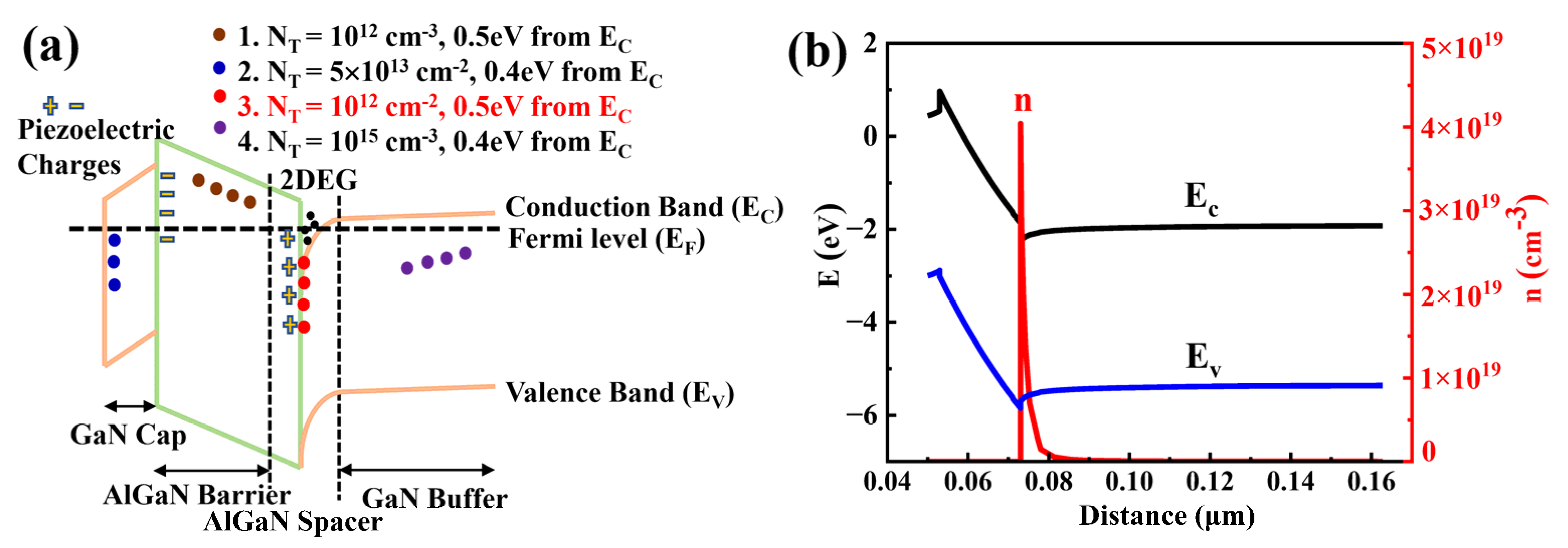
To simulate the degradation characteristic of the device under hot carrier stress, various kinds of defects are generated and added to the GaN model. Initial interface trap concentrations of 3 × 10¹²–9 × 1012 cm−2 are widely reported [34]. Donor-type interface defect traps with a density of 5 × 10¹³/cm2 were activated at the interface of the passivation layer and GaN cap, as specified in Figure 3a. Bulk acceptor traps with a density of 1015/cm3 are activated in the GaN buffer. The acceptor trap density of 1012/cm3 is declared for both AlGaN barriers. All the traps considered are located 0.4/0.5 eV from the conduction band, according to Refs. [35,36,37,38,39]. Figure 3a shows the energy band diagram and electron density distribution at 300 K for the designed structure in TCAD simulation. It can be seen that electrons mainly accumulate in the channel region of GaN (i.e., 2-DEG is confined in the GaN_channel with a thickness of 5 nm) with a maximum electron concentration of 4 × 1019 cm−3, and the energy bandgap is approximately 3 eV, which is similar to that of practical GaN HEMTs.
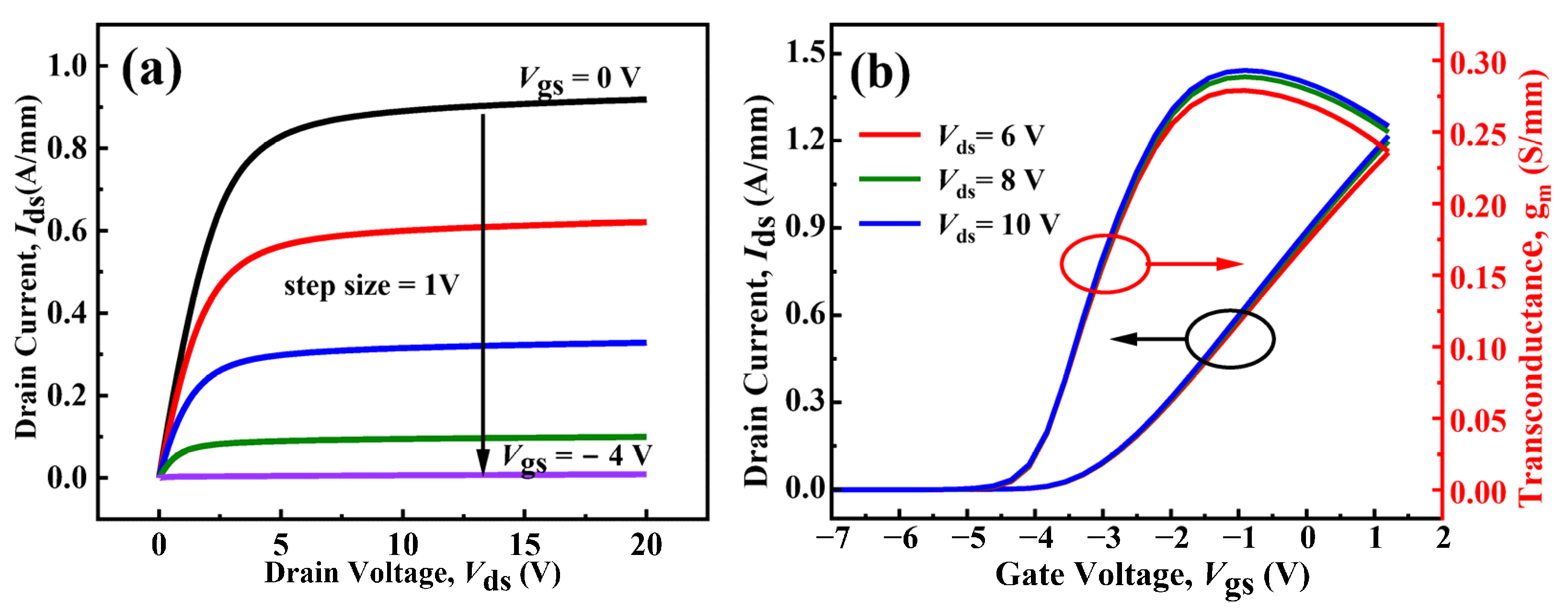
Figure 4 shows the simulated I-V characteristics of the D-GaN HEMTs before the hot carrier stress. The DC output characteristics of GaN HEMTs were determined by sweeping the gate voltage bias (Vgs) from 0 to −4 V and the drain voltage bias (Vds) from 0 to 10 V (Figure 4a). The peak Ids is ~0.9 A/mm at bias voltages of Vgs = 0 V and Vds = 10 V. The extracted 2-DEG and mobility in the channel are 1.14 × 1013 cm−2 and 1260 cm2/V-s, respectively. Figure 4b shows the transfer and transconductance curves of GaN HEMTs when Vgs is swept from −7 to 2 V and Vds from 6 to 8 V. It is found that the threshold voltage of the device is approximately −3.86 V, and the peak value of transconductance (gm) is 0.3 S/mm when Vds = 10 V. In order to verify the accuracy of this modeling method, we conducted TCAD model construction and simulation for asymmetric T-gate GaN/AlGaN HEMT in Ref. [14]. The predicted output characteristics and transfer curves are displayed in Figure 5a,b, respectively. It is worth noting that when the Vds is lower than 7 V, there is a difference between the simulation and the experimental data, which may be caused by the material growth process and device preparation process of the sample. However, the simulated DC characteristics almost exactly match the experimental Ids-Vds at the saturation region. This means that the modeling method is feasible for studying the reliability degradation of GaN HEMTs.

3.2. Degradation Results for GaN HEMTs

Hot carrier stress is usually found to reduce the drain current [17,40]. During hot-electron stress, channel electrons (such as 2-DEG) are heated at the gate and gate-drain extension regions. A large fraction of these hot electrons directly collides with the interface, resulting in the generation of the interface states [10]. A famous HCI model that describes the relationship between the number of interface states ∆Nit near the drain terminal and the hot-electron stress [41,42] is shown as follows:
Δ N i t = C I d t W e φ i t q λ E m n = C 1 I d t W e β V d s V g s V t h n
in which Em = (VdsVdsat)/L, Vdsat = VgsVth, and β = φit L/(); φit is the critical energy that an electron must have to create an interface trap, which is determined by experiment. λ is the hot-electron mean-free path. W is the channel width. N is the power factor, and t is the stress time. In this simulation, the specific parameter values used are shown in Table 2.
To simulate the device characteristics under hot carrier stress, we introduce an acceptor-type interface trap with concentration varying through time being uniformly distributed at the AlGaN/GaN interface. The variation in trap concentration is set according to Formula (1). In this work, the acceptor energy level at each concentration is fixed at 0.5 eV. Additionally, electron and hole capture cross sections of 1 × 10⁻¹⁵ cm2 are used for the trap level, which is consistent with other reported numerical simulations [37,38]. The parameter variations are performed under degradation-free initial conditions. The specific simulation details are given as follows. (1) The variation in defects with time induced by hot-electron effects is obtained based on the change in gate voltage Vgs and drain voltage Vds. (2) The concentration of defects as a function of time is added to the AlGaN/GaN interface in the GaN HEMT model. (3) The variation in device characteristics with time is obtained at a given gate voltage Vgs and drain voltage Vds.
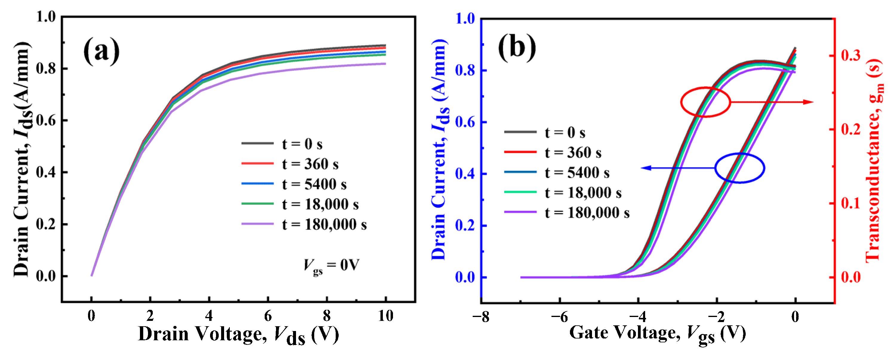
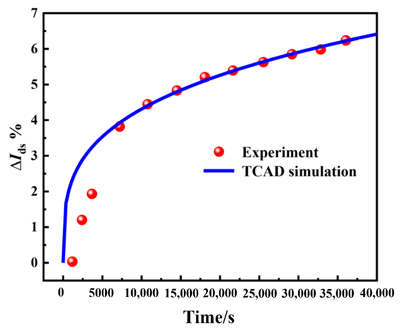
The drain current variation in the GaN model with time under hot-electron stress (Vgs = −1 V, Vds = 30 V) is simulated. Figure 6 shows the reduction in the drain current (measured at Vds = 10 V, Vgs = 0 V) obtained. It can be seen that Ids gradually decreases at constant Vgs = 0 V with increasing time. After 1.8 × 10⁵ s, the drain current decreases from 0.890 to 0.810 A/mm, dropping by 8.9%. Furthermore, on-state stress is found to induce a decrease in maximum transconductance but no significant change in the threshold voltage of the devices (see Figure 6b). The observed strong variation in the drain current during stress can be explained by the trapping of electrons in the channel region, which corresponds to the continuous degradation of the device [10]. Furthermore, the variation in the drain current of the GaN model with time under hot-electron stress (Vgs = −1 V, Vds = 30 V) based on the method above is compared with the degradation of the device in Ref. [13]. The results are shown in Figure 7. Here, a decrease in drain current is replaced by the Ids degradation rate (%); that is, ΔIds = (Ids_strIds0)/Ids0 × 100%, Ids_str means Ids after stress with t time, and Ids0 means Ids before stress. The comparison results show that the predicted ΔIds% with time is consistent with the reported results under the same hot-electron stress, which indicates that the degradation law of the GaN HEMTs reacted in this work agrees with the actual trend.
Numerous groups of Vds and Vgs specific stresses can result in various Ids degradation, which can be observed in the simulation. To handle the multidimensional and multivariable stress on the device behavior, 2250 groups of degradation data under specific Vds and Vgs were obtained based on the above methods, which were used for the subsequent training of the ML methods.

4. ML Algorithms for HCI Degradation

The ML algorithms are employed to predict the performance changes in devices based on the simulation data. The details of the ML algorithms for predicting the performance degradation of GaN HEMTs, shown in Figure 1, are described in subsequent steps.
(1) Data preprocessing, which includes scaling, normalizing, grouping, and removing the outliers of the training data. Scaling is achieved by subtracting the mean of each feature and dividing by the standard deviation:
z = x μ x σ x
where μx is the mean of x and σx is the standard deviation of x.
(2) Dataset separating. The dataset is divided into three groups: training, validation, and testing. Testing data are used to evaluate the accuracy of these trained algorithms.
(3) An ML algorithm such as ANN is designed based on the training dataset.
(4) ML algorithms are trained multiple times until fitting.
In addition, to minimize the situation of underfitting or overfitting, a cross-validation approach is used to ensure that the model is generalized to an independent or unseen dataset.
Figure 8 shows the ANN structure consisting of an input layer, hidden layers, and an output layer. These layers are connected through weights-driven connections. Increasing the model’s topology simultaneously affects the model’s complexity, which in turn upsets the simulation time of the model. Thus, we carefully changed the model’s parameters and repeated the same steps until we obtained the best topology for this problem. The proposed model’s topology consists of two inputs Vgs and Vds, four hidden layers, and an output layer. The four hidden layers have 30, 80, 100, and 100 neurons, respectively. The output layer has 59 neurons with a neuron dropout rate of 0.2. The output vector is the variation in Ids as a function of time. In addition, each perceptron has an ReLU activation function for fast learning and avoiding gradient loss. These layers are linked together to achieve progressive data distillation.
The fitness function of the algorithm is evaluated in terms of the mean square error (MSE). When the value of MSE is met, the loss no longer decreases, and the ANN algorithm ends the training process. The loss function and MSE are given by
φ ( x ) = max ( 0 , x )
M S E = 1 n i = 1 n ( y i y ^ i ) 2
where n is the total sample size; y i and y ^ i are the actual and prediction results, respectively.
Additionally, backpropagation adopts Adam’s algorithm with good stability and fast convergence speed. To avoid overfitting or underfitting in ANN training, 200 epochs are chosen for gradient descent optimization.
In addition, the decision tree (DT) and ridge regression (RR) are also constructed. After these algorithms are constructed, the dataset (obtained from Section 3) is processed and input into the algorithms, as shown in Figure 1. Then, the ML algorithm is repeatedly trained until a validated output set is generated. Once the model is validated, it is able to generate the output from the input parameters of the device. Trained models are then used to predict the results for different conditions that are the output of the original datasets.

5. Results and Discussion

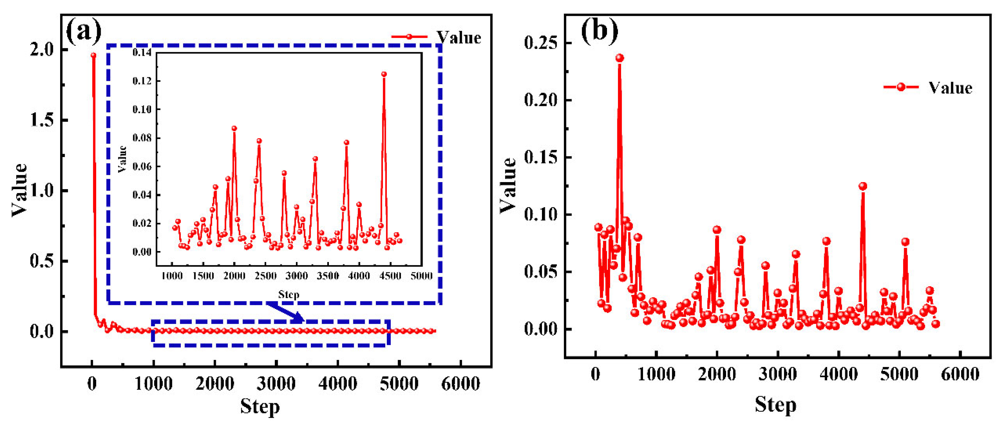
Figure 9 shows the losses of the ANN algorithm as a function of steps. After a few epochs of training, the loss function begins to decrease, and the algorithm begins the learning of the Ids degradation as a function of time under different Vds and Vgs. The loss value reaches a minimum value after a few epochs and then stabilizes around a fixed value. Figure 9a,b show that the training has converged and that there is no overfitting with excellent algorithm generalization ability. As a result, the ANN algorithm is trained for 1000 epochs and it completely learns the behavior of the GaN HEMTs under the hot-electron effects. The trained algorithm becomes an equation solver that can instantaneously predict the Ids degradation as a function of time under various hot-electron conditions.
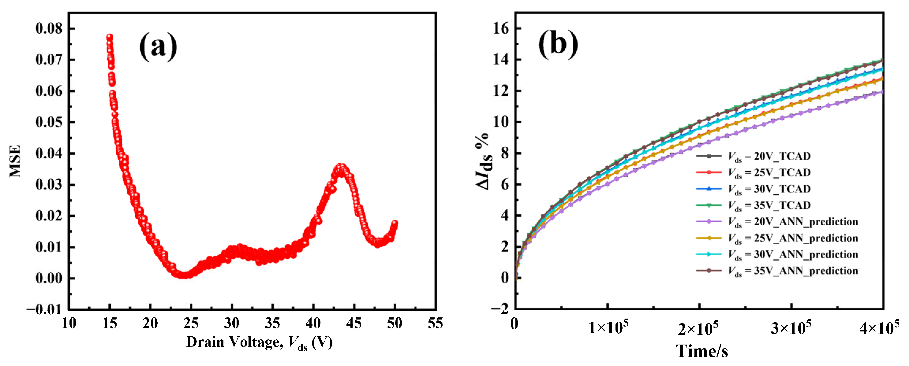
Figure 10a shows the MSE values between the developed ANN algorithm and the simulation results with a variable drain voltage varying in the range 15–50 V. It is easy to note that the MSE of the ANN algorithm is less than 0.1. This means that the ANN algorithm possesses great accuracy in terms of Ids change with time under hot-electron effects. Hot-electron stress of Vds = 20–35 V and a step size of 5 V are taken as an example, as shown in Figure 10b. In the initial state, when the stress time is short, Ids remains almost unchanged (ΔIds = 0). After that, the GaN HEMT shows signs of degradation. This stage is the continuous degradation stage. With the accumulation of time, more defects are generated by the hot-electron effects, so ΔIds changes exponentially. It can be seen that the training result almost coincides with the predicted values of the ANN algorithm. This means that the ANN algorithm successfully understood the deep relationship between hot-electron stress and Ids degradation of the GaN HEMTs.
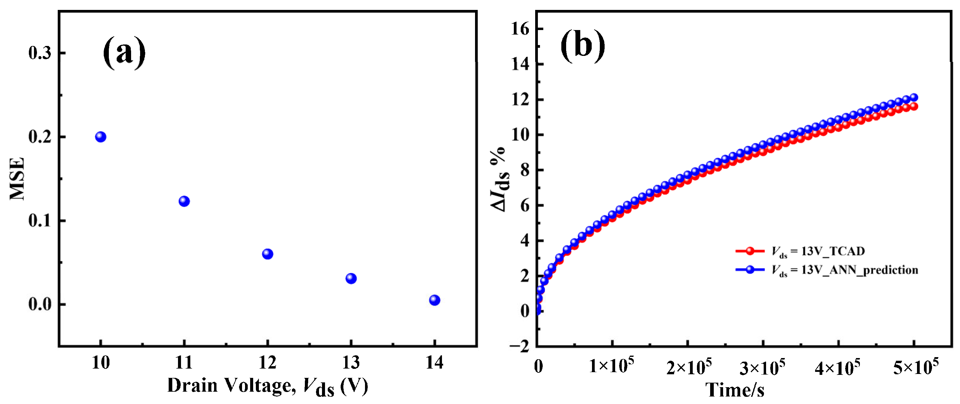
A value of Vds lower than 15 V is used to verify the extrapolation ability of the ML algorithm. The MSE between the predicted values of the algorithm and simulation values with the drain voltage varying in the range 10–14 V is shown in Figure 11a. As the drain voltage decreases (i.e., away from the drain voltage training range), the MSE increases gradually to a maximum of 0.2. Taking normal working conditions as an example (Vds = 13 V) in Figure 11b, in the initial stage, the prediction of the ANN algorithm coincides completely with the actual curve. As time passes, the predictably extrapolated results of the ANN algorithm gradually deviate from the actual results, as shown by the solid blue line and dashed red line. In addition, the ability of the ANN model to predict the lifetime of GaN devices is evaluated, as shown in Figure 12. The evaluation criteria of HCI lifetime are normally defined as 10% variation in Ids with time. According to Formula (1), the abscissa is 1/(VdsVdsat), and the ordinate is the corresponding time when the sIds of the device degrades to 10%. In the early stage, the prediction of the ANN model is relatively accurate and almost consistent with the TCAD simulation results. Under normal working conditions (Vds = 10 V), the simulated lifetime of GaN HEMTs simulated by TCAD is 4.4 × 10⁵ s, while the lifetime predicted by the ANN model is 4.2 × 10⁵ s, which is consistent with the previous conclusion. In summary, these test results show that the ANN algorithm can quickly predict the performance degradation of the device without knowing the physical background of the hot-electron effects.
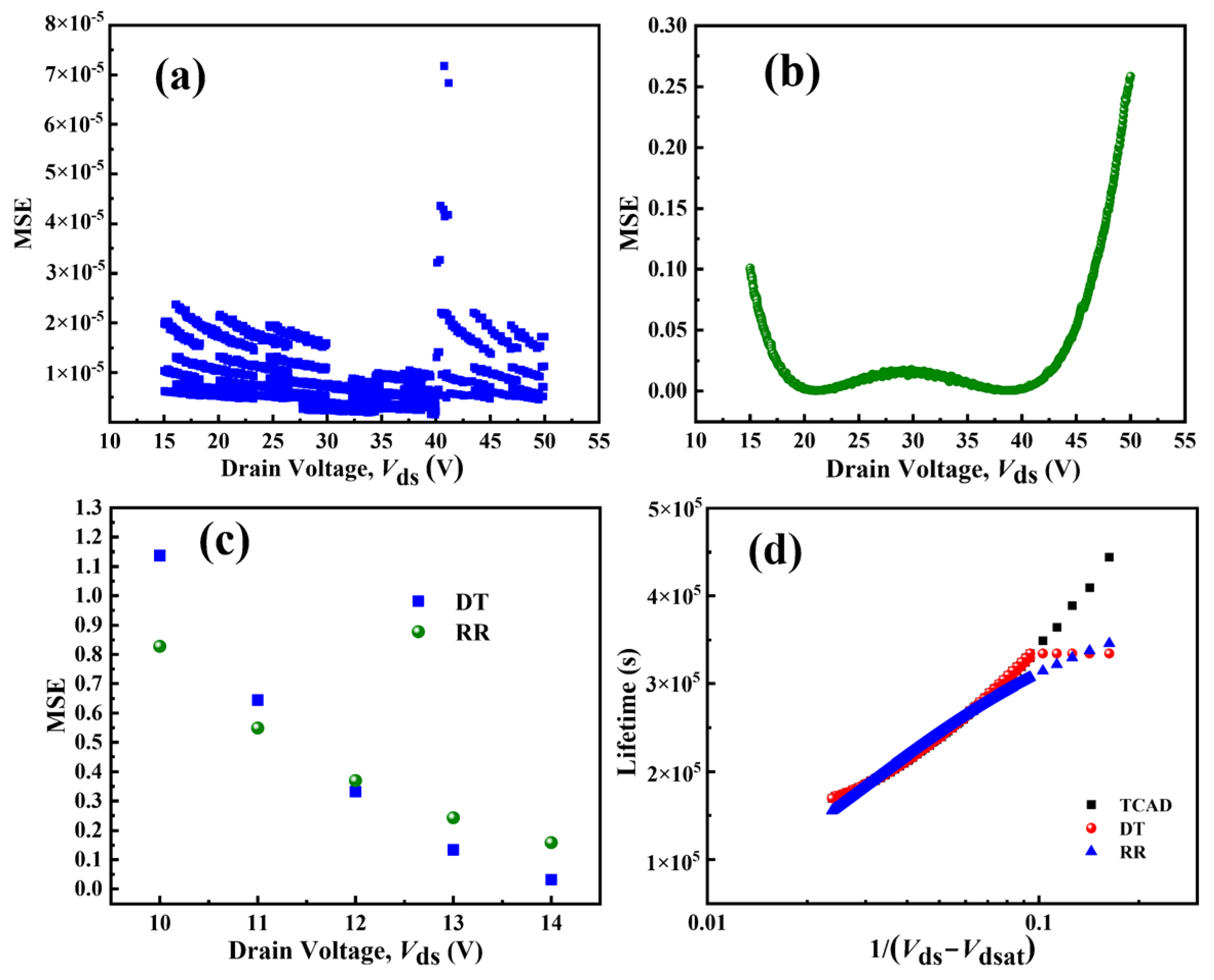
The decision tree (DT) and ridge regression (RR) are also employed to predict the performance changes in devices under hot-electron effects. To evaluate the performance of the two models, we compared the prediction ability of the models under stress (15–50 V) and normal operating conditions (10–14 V). Figure 13a,b compare the MSE values of the two algorithms when the drain voltage varies from 15 to 50 V. It is easy to note that the MSE of the DT algorithm is minimal, almost zero, while the RR algorithm has the largest MSE of approximately 0.25. This means that the DT algorithm possesses great accuracy in terms of Ids change with time under hot-electron effects. However, the algorithm developed by the DT is the least accurate in terms of prediction outside the trained range, as shown in Figure 13c. The trend is consistent with the change in ANN in the extrapolated range, and MSE increases with the decrease in drain voltage. The maximum MSE values of DT and RR are 1.1368 and 0.8277, respectively. In addition, the lifetime prediction of GaN devices by the two algorithms is shown in Figure 13d. When the DT algorithm is extrapolated, the predicted data remain unchanged, as shown in the red scatter, which may be attributed to the fact that the DT relies on cut points that are specific to the inputs, leading to overfitting and poor algorithm generalization. The value of MSE between the RR algorithm and TCAD simulation results is large in the training dataset. When Vds = 10 V, that is, 1/(VdsVdsat) = 0.1629, the prediction results of the DT and RR models are worse than those of the ANN model. Among them, the predicted lifetime of GaN HEMTs by the DT model is approximately 3.3 × 10⁵ s, and that of GaN devices by the RR model is approximately 3.4 × 10⁵ s. Compared with the actual simulated lifetime through TCAD, the difference is 1.1 × 10⁵ s and 1 × 10⁵ s, respectively.
In summary, the proposed TCAD-ANN model not only has high accuracy within the training data range, with MSE on the order of 10−2, but also has high accuracy outside the training data range, with a minimum MSE of 0.2. These results demonstrate that ANN models promise to give faster and more accurate outputs in GaN HEMTs modeling and predicting its performance under hot-electron stress. This work provides an alternative way to predict the degradation evaluation of GaN HEMTs; trained ML models can be directly used to study the performance degradation of GaN HEMTs under different thermal electron stresses not analyzed using TCAD simulator or experiments, which corresponds to accelerating the lifetime prediction of the GaN device and benefits the product’s development.

6. Conclusions

An ML-TCAD coupled model is proposed to predict the performance degradation of GaN HEMTs induced by hot-electron effects, which does not require knowledge of complex reliability physics, long-term experimental testing, or numerous TCAD simulations. Results show that the ML-TCAD coupled model with three ML algorithms can successfully reflect the ΔIds variations in the GaN HEMTs under hot-electron stress and exhibit promising predictable results. In the next research, we will combine the mature ML-TCAD model with the reliability experiment. The traps location, distribution, concentration, and energy-level positions in GaN HEMTs can be deduced reverse-through the degradation curve of the device (such as the Ids-Vds, Ids-Vgs curve after a certain time of stress). This will be helpful to further explore the physical degradation mechanism of GaN HEMTs under hot-electron stress.

Author Contributions

K.W.: acquisition, analysis, and interpretation of data for the work; methodology; and writing—original draft. H.J.: software; methodology; and validation. Y.L.: writing—review and editing; supervision; and visualization. Y.X.: formal analysis and writing—review and editing. F.Y.: funding acquisition and resources; X.J.: supervision; substantial contributions to the conception or design of the work; and agreed to be accountable for all aspects of the work. All authors have read and agreed to the published version of the manuscript.

Funding

This research received no external funding.

Acknowledgments

This work was supported by the National Nature Science Foundation of China (61627804), National Key Research and Development Program of China (2016YFB0402403, 2016YFB0400402), and Key Laboratory of Infrared Imaging Materials and Detectors (IIMDKFJJ-19-07).

Conflicts of Interest

The authors declare no conflict of interest.

References

  1. Sun, R.; Lai, J.; Chen, W.; Zhang, B. GaN Power Integration for High Frequency and High Efficiency Power Applications: A Review. IEEE Access 2020, 8, 15529–15542. [Google Scholar] [CrossRef]
  2. Chen, K.J.; Haberlen, O.; Lidow, A.; Tsai, C.L.; Ueda, T.; Uemoto, Y.; Wu, Y. GaN-on-Si Power Technology: Devices and Applications. IEEE Trans. Electron Devices 2017, 64, 779–795. [Google Scholar] [CrossRef]
  3. Oka, T. Recent Development of Vertical GaN Power Devices. Jpn. J. Appl. Phys. 2019, 58, SB0805. [Google Scholar] [CrossRef]
  4. Chu, R. GaN Power Switches on the Rise: Demonstrated Benefits and Unrealized Potentials. Appl. Phys. Lett. 2020, 116, 090502. [Google Scholar] [CrossRef]
  5. Gryglewski, D.; Wojtasiak, W.; Kamińska, E.; Piotrowska, A. Characterization of Self-Heating Process in Gan-Based Hemts. Electronics 2020, 9, 1305. [Google Scholar] [CrossRef]
  6. Meneghini, M.; Stocco, A.; Bertin, M.; Marcon, D.; Chini, A.; Meneghesso, G.; Zanoni, E. Time-Dependent Degradation of AlGaN/GaN High Electron Mobility Transistors under Reverse Bias. Appl. Phys. Lett. 2012, 100, 033505. [Google Scholar] [CrossRef]
  7. Cai, X.; Du, C.; Sun, Z.; Ye, R.; Liu, H.; Zhang, Y.; Duan, X.; Lu, H. Recent Progress of Physical Failure Analysis of GaN HEMTs. J. Semicond. 2021, 42, 051801. [Google Scholar] [CrossRef]
  8. Amar, A.; Radi, B.; El Hami, A. Electrothermal Reliability of the High Electron Mobility Transistor (Hemt). Appl. Sci. 2021, 11, 10720. [Google Scholar] [CrossRef]
  9. Angelotti, A.M.; Gibiino, G.P.; Florian, C.; Santarelli, A. Trapping Dynamics in Gan Hemts for Millimeter-Wave Applications: Measurement-Based Characterization and Technology Comparison. Electronics 2021, 10, 137. [Google Scholar] [CrossRef]
  10. Sahoo, D.K.; Lal, R.K.; Kim, H.; Tilak, V.; Eastman, L.F. High-Field Effects in Silicon Nitride Passivated GaN MODFETs. IEEE Trans. Electron Devices 2003, 50, 1163–1170. [Google Scholar] [CrossRef]
  11. Meneghesso, G.; Meneghini, M.; Stocco, A.; Bisi, D.; de Santi, C.; Rossetto, I.; Zanandrea, A.; Rampazzo, F.; Zanoni, E. Degradation of AlGaN/GaN HEMT Devices: Role of Reverse-Bias and Hot Electron Stress. Microelectron. Eng. 2013, 109, 257–261. [Google Scholar] [CrossRef]
  12. Rao, H.; Bosman, G. Hot-Electron Induced Defect Generation in AlGaN/GaN High Electron Mobility Transistors. Solid. State. Electron. 2013, 79, 11–13. [Google Scholar] [CrossRef]
  13. Meneghini, M.; Stocco, A.; Silvestri, R.; Meneghesso, G.; Zanoni, E. Degradation of AlGaN/GaN High Electron Mobility Transistors Related to Hot Electrons. Appl. Phys. Lett. 2012, 100, 233508. [Google Scholar] [CrossRef]
  14. Meneghini, M.; Stocco, A.; Silvestri, R.; Ronchi, N.; Meneghesso, G.; Zanoni, E. Impact of Hot Electrons on the Reliability of AlGaN/GaN High Electron Mobility Transistors. In Proceedings of the 2012 IEEE International Reliability Physics Symposium (IRPS), Anaheim, CA, USA, 15–19 April 2012. [Google Scholar] [CrossRef]
  15. Bisi, D.; Chini, A.; Soci, F.; Stocco, A.; Meneghini, M.; Pantellini, A.; Nanni, A.; Lanzieri, C.; Gamarra, P.; Lacam, C.; et al. Hot-Electron Degradation of AlGaN/GaN High-Electron Mobility Transistors during RF Operation: Correlation with GaN Buffer Design. IEEE Electron Device Lett. 2015, 36, 1011–1014. [Google Scholar] [CrossRef]
  16. Ruzzarin, M.; Meneghini, M.; Rossetto, I.; van Hove, M.; Stoffels, S.; Wu, T.L.; Decoutere, S.; Meneghesso, G.; Zanoni, E. Evidence of Hot-Electron Degradation in GaN-Based MIS-HEMTs Submitted to High Temperature Constant Source Current Stress. IEEE Electron Device Lett. 2016, 37, 1415–1417. [Google Scholar] [CrossRef]
  17. Gao, Z.; Rampazzo, F.; Meneghini, M.; de Santi, C.; Chiocchetta, F.; Marcon, D.; Meneghesso, G.; Zanoni, E. Degradation Mechanism of 0.15 Μm AlGaN/GaN HEMTs: Effects of Hot Electrons. Microelectron. Reliab. 2020, 114, 113905. [Google Scholar] [CrossRef]
  18. Chen, X.; Boumaiza, S.; Wei, L. Modeling Bias Dependence of Self-Heating in GaN HEMTs Using Two Heat Sources. IEEE Trans. Electron Devices 2020, 67, 3082–3087. [Google Scholar] [CrossRef]
  19. Valletta, A.; Mussi, V.; Rapisarda, M.; Lucibello, A.; Natali, M.; Peroni, M.; Lanzieri, C.; Fortunato, G.; Mariucci, L. Hybrid Electrothermal Simulations of GaN HEMT Devices Based on Self-Heating Free Virtual Electrical Characteristics. IEEE Trans. Electron Devices 2021, 68, 3740–3747. [Google Scholar] [CrossRef]
  20. Murugapandiyan, P.; Nirmal, D.; Tanvir Hasan, M.; Varghese, A.; Ajayan, J.; Augustine Fletcher, A.S.; Ramkumar, N. Influence of AlN Passivation on Thermal Performance of AlGaN/GaN High-Electron Mobility Transistors on Sapphire Substrate: A Simulation Study. Mater. Sci. Eng. B Solid State Mater. Adv. Technol. 2021, 273, 115449. [Google Scholar] [CrossRef]
  21. Minetto, A.; Deutschmann, B.; Modolo, N.; Nardo, A.; Meneghini, M.; Zanoni, E.; Sayadi, L.; Prechtl, G.; Sicre, S.; Haberlen, O. Hot-Electron Effects in AlGaN/GaN HEMTs under Semi-ON DC Stress. IEEE Trans. Electron Devices 2020, 67, 4602–4605. [Google Scholar] [CrossRef]
  22. Mukherjee, K.; Darracq, F.; Curutchet, A.; Malbert, N.; Labat, N. TCAD Simulation Capabilities towards Gate Leakage Current Analysis of Advanced AlGaN/GaN HEMT Devices. Microelectron. Reliab. 2017, 76–77, 350–356. [Google Scholar] [CrossRef]
  23. Mishra, S.; Chaturvedi, N. Multi-Output Deep Learning Model for Simultaneous Prediction of Figure of Merits (I on, G m, and v Th) of Gallium Nitride High Electron Mobility Transistors. J. Appl. Phys. 2022, 131, 064901. [Google Scholar] [CrossRef]
  24. Abubakr, A.; Hassan, A.; Ragab, A.; Yacout, S.; Savaria, Y.; Sawan, M. High-Temperature Modeling of the I-V Characteristics of GaN150 HEMT Using Machine Learning Techniques. In Proceedings of the 2018 IEEE International Symposium on Circuits and Systems (ISCAS), Florence, Italy, 27–30 May 2018. [Google Scholar] [CrossRef]
  25. Jarndal, A. GaN HEMT Electrothermal Modeling Using Feedback Neural Networks Technique. In Proceedings of the 2019 International Conference on Electrical and Computing Technologies and Applications (ICECTA), Ras Al Khaimah, United Arab Emirates, 19–21 November 2019. [Google Scholar] [CrossRef]
  26. Vicente, J.G.; Serrano, D.; Vasic, M. Test Bench Setup for Characterization of GaN HEMT. In Proceedings of the 2021 21st International Symposium on Power Electronics (Ee), Novi Sad, Serbia, 27–30 October 2021. [Google Scholar] [CrossRef]
  27. Khusro, A.; Husain, S.; Hashmi, M.S.; Ansari, A.Q. Small Signal Behavioral Modeling Technique of GaN High Electron Mobility Transistor Using Artificial Neural Network: An Accurate, Fast, and Reliable Approach. Int. J. RF Microw. Comput. Eng. 2020, 30, e22112. [Google Scholar] [CrossRef]
  28. Wang, Z.; Li, L.; Yao, Y. A Machine Learning-Assisted Model for GaN Ohmic Contacts Regarding the Fabrication Processes. IEEE Trans. Electron Devices 2021, 68, 2212–2219. [Google Scholar] [CrossRef]
  29. Wu, T.L.; Kutub, S. Bin Machine Learning-Based Statistical Approach to Analyze Process Dependencies on Threshold Voltage in Recessed Gate AlGaN/GaN MIS-HEMTs. IEEE Trans. Electron Devices 2020, 67, 5448–5453. [Google Scholar] [CrossRef]
  30. Mishra, S.; Gaikwad, B.; Chaturvedi, N. Semi-Supervised Physics Guided Deep Learning Framework for Predicting the I-V Characteristics of GAN HEMT. arXiv 2021, arXiv:2110.10724. [Google Scholar]
  31. Vigneshwara Raja, P.; Nallatamby, J.C.; DasGupta, N.; DasGupta, A. Trapping Effects on AlGaN/GaN HEMT Characteristics. Solid. State. Electron. 2021, 176, 107929. [Google Scholar] [CrossRef]
  32. Das, S.; Kumari, V.; Sehra, K.; Gupta, M.; Saxena, M. TCAD Based Investigation of Single Event Transient Effect in Double Channel AlGaN/GaN HEMT. IEEE Trans. Device Mater. Reliab. 2021, 21, 416–423. [Google Scholar] [CrossRef]
  33. Chaudhuri, R.R.; Joshi, V.; Gupta, S.D.; Shrivastava, M. On the Channel Hot-Electron’s Interaction with C-Doped GaN Buffer and Resultant Gate Degradation in AlGaN/GaN HEMTs. IEEE Trans. Electron Devices 2021, 68, 4869–4876. [Google Scholar] [CrossRef]
  34. Faqir, M.; Verzellesi, G.; Meneghesso, G.; Zanoni, E.; Fantini, F. Investigation of High-Electric-Field Degradation Effects in AlGaN/GaN HEMTs. IEEE Trans. Electron Devices 2008, 55, 1592–1602. [Google Scholar] [CrossRef]
  35. Faqir, M.; Bouya, M.; Malbert, N.; Labat, N.; Carisetti, D.; Lambert, B.; Verzellesi, G.; Fantini, F. Analysis of Current Collapse Effect in AlGaN/GaN HEMT: Experiments and Numerical Simulations. Microelectron. Reliab. 2010, 50, 1520–1522. [Google Scholar] [CrossRef]
  36. Miccoli, C.; Martino, V.C.; Reina, S.; Rinaudo, S. Trapping and Thermal Effects Analysis for AlGaN/GaN HEMTs by Means of TCAD Simulations. IEEE Electron Device Lett. 2013, 34, 1121–1123. [Google Scholar] [CrossRef]
  37. Zhou, X.; Feng, Z.; Wang, Y.; Gu, G.; Song, X.; Cai, S. Transient Simulation of AlGaN/GaN HEMT Including Trapping and Thermal Effects. In Proceedings of the 2014 12th IEEE International Conference on Solid-State and Integrated Circuit Technology (ICSICT), Guilin, China, 28–31 October 2014. [Google Scholar] [CrossRef]
  38. Yang, J.; Cui, S.; Ma, T.P.; Hung, T.H.; Nath, D.; Krishnamoorthy, S.; Rajan, S. Determination of Trap Energy Levels in AlGaN/GaN HEMT. In Proceedings of the 71st Device Research Conference, Notre Dame, IN, USA, 23–26 June 2013; pp. 79–80. [Google Scholar] [CrossRef]
  39. Zhang, W.; Zhang, Y.; Mao, W.; Ma, X.; Zhang, J.; Hao, Y. Influence of the Interface Acceptor-like Traps on the Transient Response of AlGaN/GaN HEMTs. IEEE Electron Device Lett. 2013, 34, 45–47. [Google Scholar] [CrossRef]
  40. Liu, C.; Chen, Y.Q.; Liu, Y.; Lai, P.; He, Z.Y.; En, Y.F.; Wang, T.Y.; Huang, Y. Effect of Atmosphere on Electrical Characteristics of AlGaN/GaN HEMTs under Hot-Electron Stress. IEEE Trans. Electron Devices 2021, 68, 1000–1005. [Google Scholar] [CrossRef]
  41. Takeda, E.; Suzuki, N. An Empirical Model for Device Degradation Due to Hot-Carrier Injection. IEEE Electron Device Lett. 1983, 4, 111–113. [Google Scholar] [CrossRef]
  42. Hu, C.; Tam, S.C.; Hsu, F.C.; Ko, P.K.; Chan, T.Y.; Terrill, K.W. Hot-Electron-Induced MOSFET Degradation—Model, Monitor, and Improvement. IEEE J. Solid State Circuits 1985, 20, 295–305. [Google Scholar] [CrossRef]
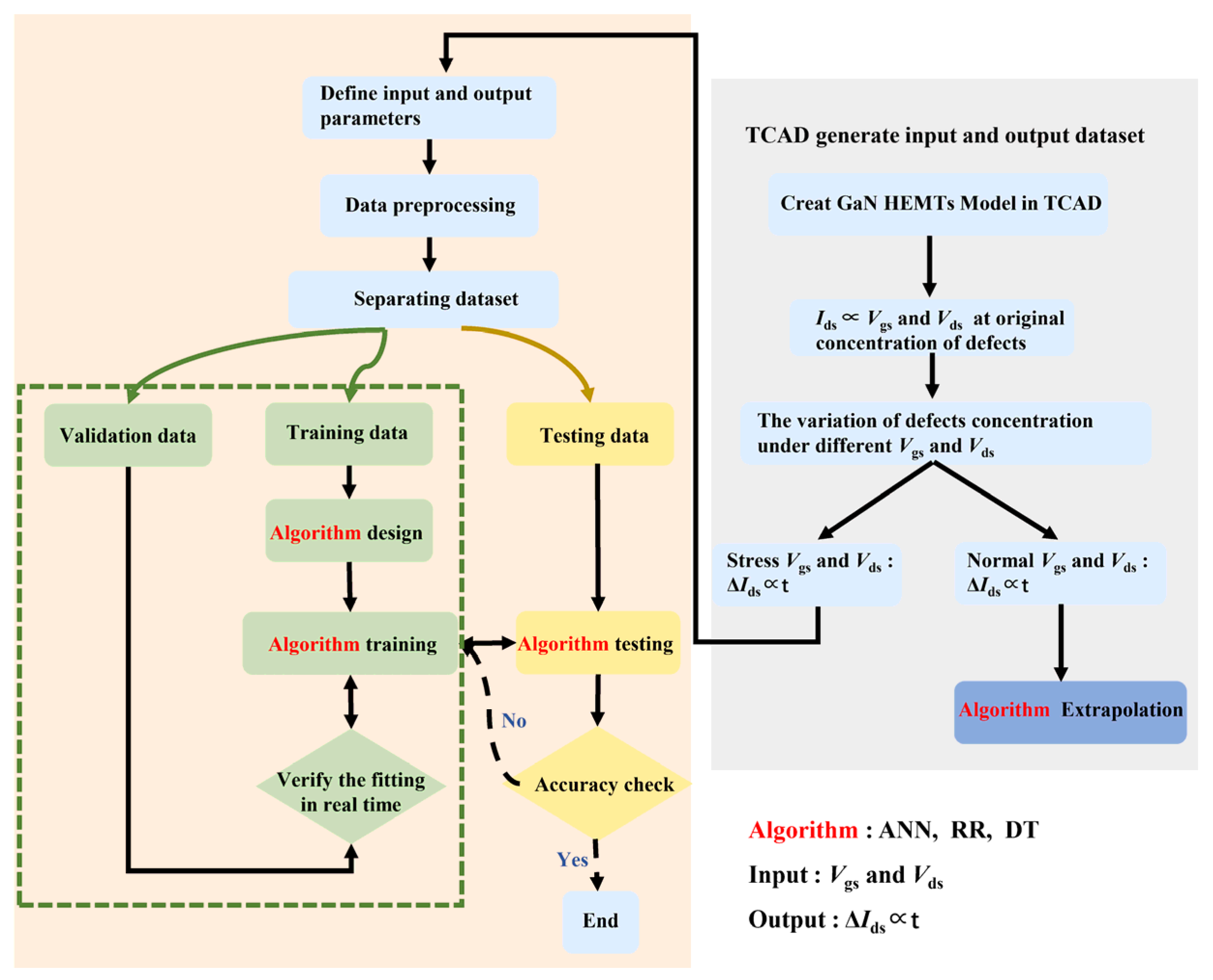
Figure 1. Flowchart of the ML-TCAD coupled model to predict the performance degradation of GaN HEMTs.
Electronics 11 03582 g001
Figure 2. Illustration of a conventional GaN/AlGaN-HEMT.
Electronics 11 03582 g002
Figure 3. (a) Band diagram illustrating simulated trap details. (b) Energy band edge (black and blue lines) and electron density (red line) in the vicinity of the channel.
Electronics 11 03582 g003
Figure 4. (a) DC characteristics of GaN HEMTs and (b) transfer and transconductance characteristics of GaN HEMTs.
Electronics 11 03582 g004
Figure 5. (a) Output characteristics of the asymmetrical T-gate AlGaN/GaN HEMT on a silicon carbide substrate with a gate length of 0.25 µm before stress and (b) transfer characteristics before stress [14].
Electronics 11 03582 g005
Figure 6. (a) I-V curve degradation of GaN HEMTs with time at hot-electron stress Vds = 30 V, Vgs = −1 V and (b) transfer and transconductance characteristic degradation of GaN HEMTs.
Electronics 11 03582 g006
Figure 7. Comparison of the degradation trend of ΔIds with time between Ref. [13] and this work under the hot-electron stress of Vds = 30 V.
Electronics 11 03582 g007
Figure 8. The ANN algorithm.
Electronics 11 03582 g008
Figure 9. Comparison of loss during ANN: (a) training and (b) verification.
Electronics 11 03582 g009
Figure 10. (a) The training MSE of ANN. (b) Comparison of the training data with predicted results.
Electronics 11 03582 g010
Figure 11. (a) The extrapolation MSE of the ANN algorithm. (b) Comparison of Ids degradation between ANN algorithm and TCAD simulation at Vds = 13 V.
Electronics 11 03582 g011
Figure 12. Comparison of the ANN algorithm in lifetime prediction.
Electronics 11 03582 g012
Figure 13. Comparison of the training data with the predicted results of (a) DT and (b) RR. (c) The extrapolation MSE of the DT and RR algorithms. (d) Comparison of two algorithms in lifetime prediction.
Electronics 11 03582 g013
Table 1. Geometric and doping concentration parameters.
StructureThickness (μm)Doping Concentration (cm−3)
SiN0.05
GaN cap0.0035 × 1018
AlGaN barrier0.022 × 1018
AlGaN spacer0.0021 × 1018
GaN buffer21 × 1018
SiC/Si0.001
Table 2. Parameters of HCI model during simulation.
ParameterValueUnit
C11 × 1012-
W1um
β1.79-
n0.28611-
Publisher’s Note: MDPI stays neutral with regard to jurisdictional claims in published maps and institutional affiliations.