
A Script-Based Cycle-True Verification Framework to Speed-Up Hardware and Software Co-Design: Performance Evaluation on ECC Accelerator Use-Case


Abstract
:1. Introduction
1.1. Related Works
1.2. Outline
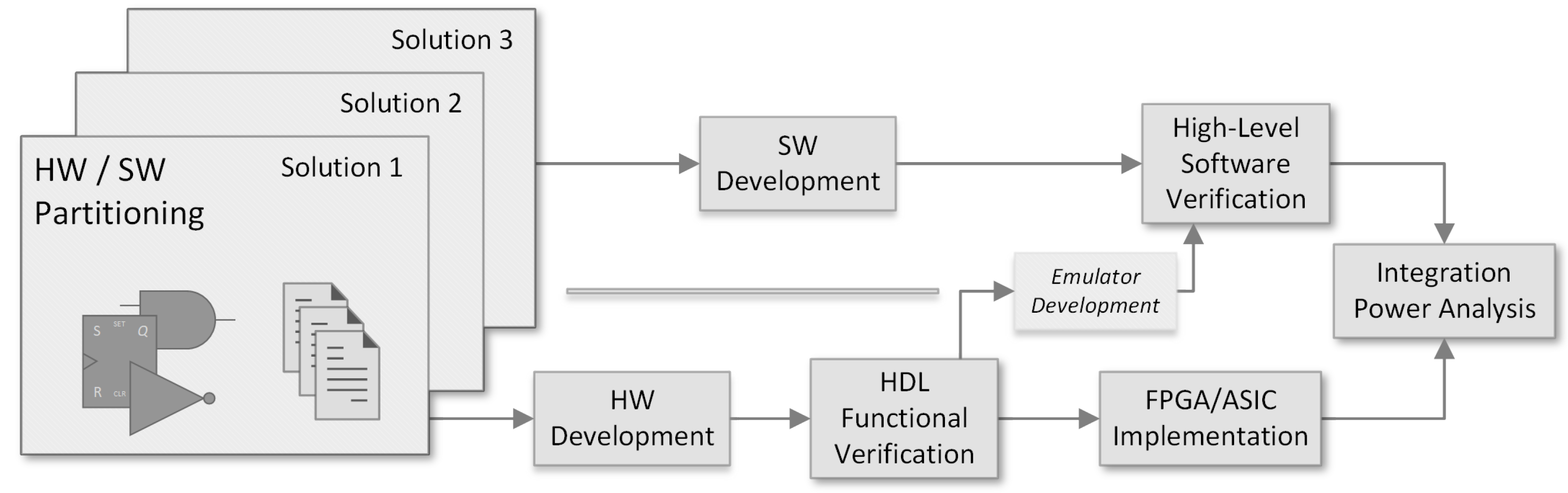
2. Our Script-Based Verification Framework
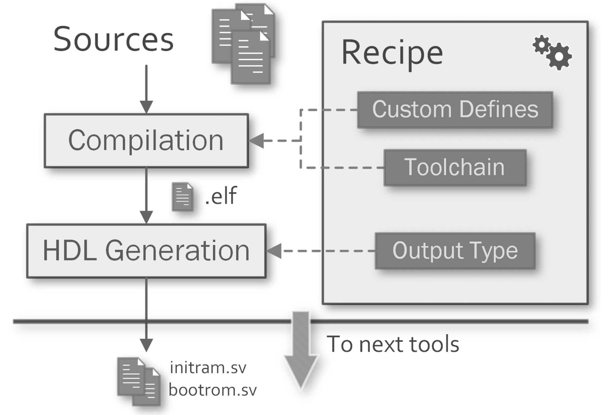
- Software Compilation: generates synthesizable Read-Only Memorys (ROMs) or simulation-only initialized Random-Access Memorys (RAMs) through RISC-V GNU Toolchain 12.1.0.
- RTL Synthesis: provides the netlists used in timing verification and power analysis through Synopsis Design Compiler 2022.03.
- RTL Simulation: performs functional and gate-level simulations (depending on whether the synthesis has been performed or not) through Mentor QuestaSIM 21.3.
- Power Analysis: provides cycle-true power consumption profiles using simulation results and synthesized netlists through Synopsis PrimeTime 2022.03.
- Default: during parallel executions, Make decide how to schedule the invocation of all targets the selected tool handlers have defined.
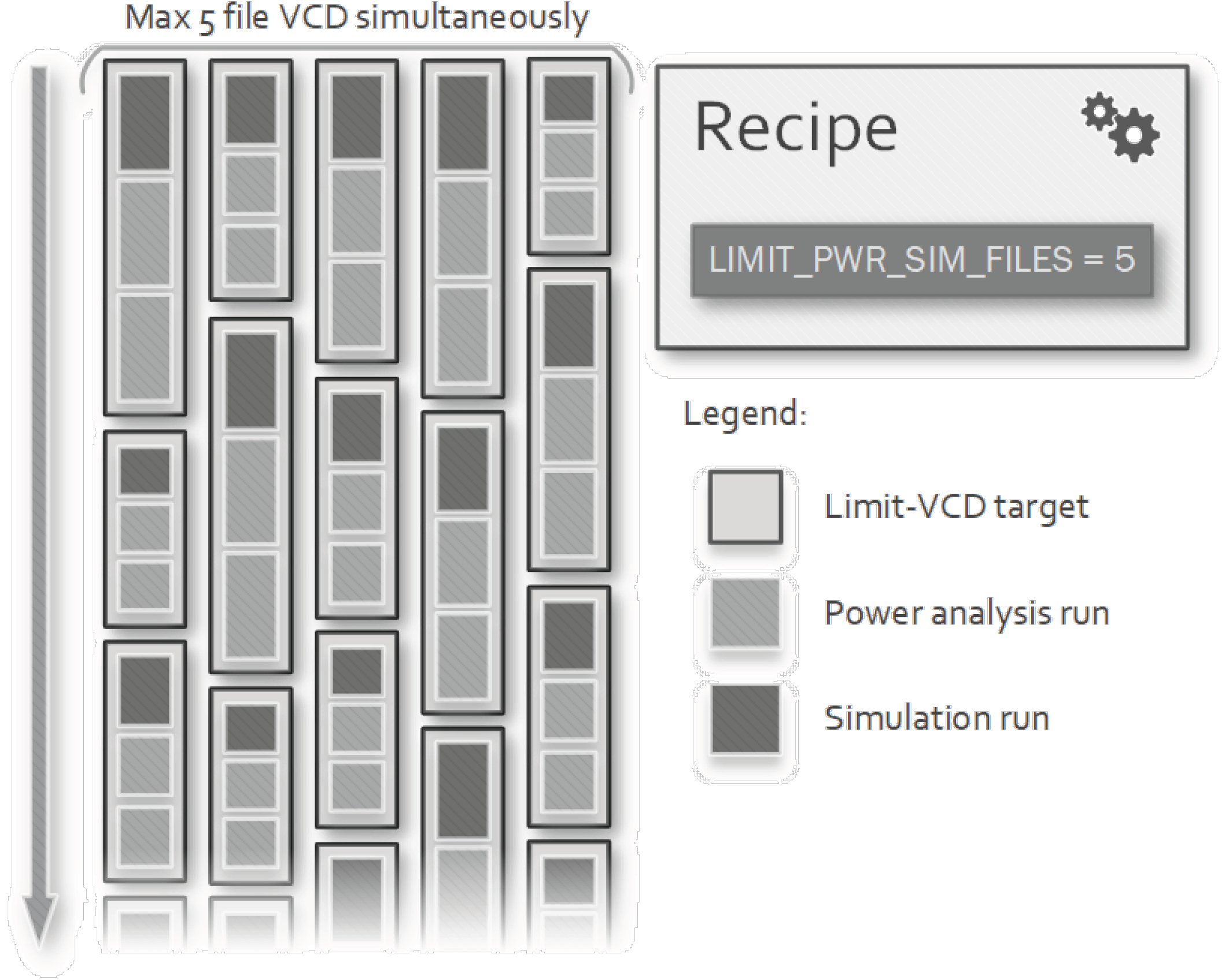
- Limited Power-Analysis: targets defined by simulation and power analysis tool handlers are grouped together to constraint their concurrent execution, thus reducing the number of Value Change Dump (VCD) files residing on the disk simultaneously. With many parallel simulations, this solution can limit disk usage.
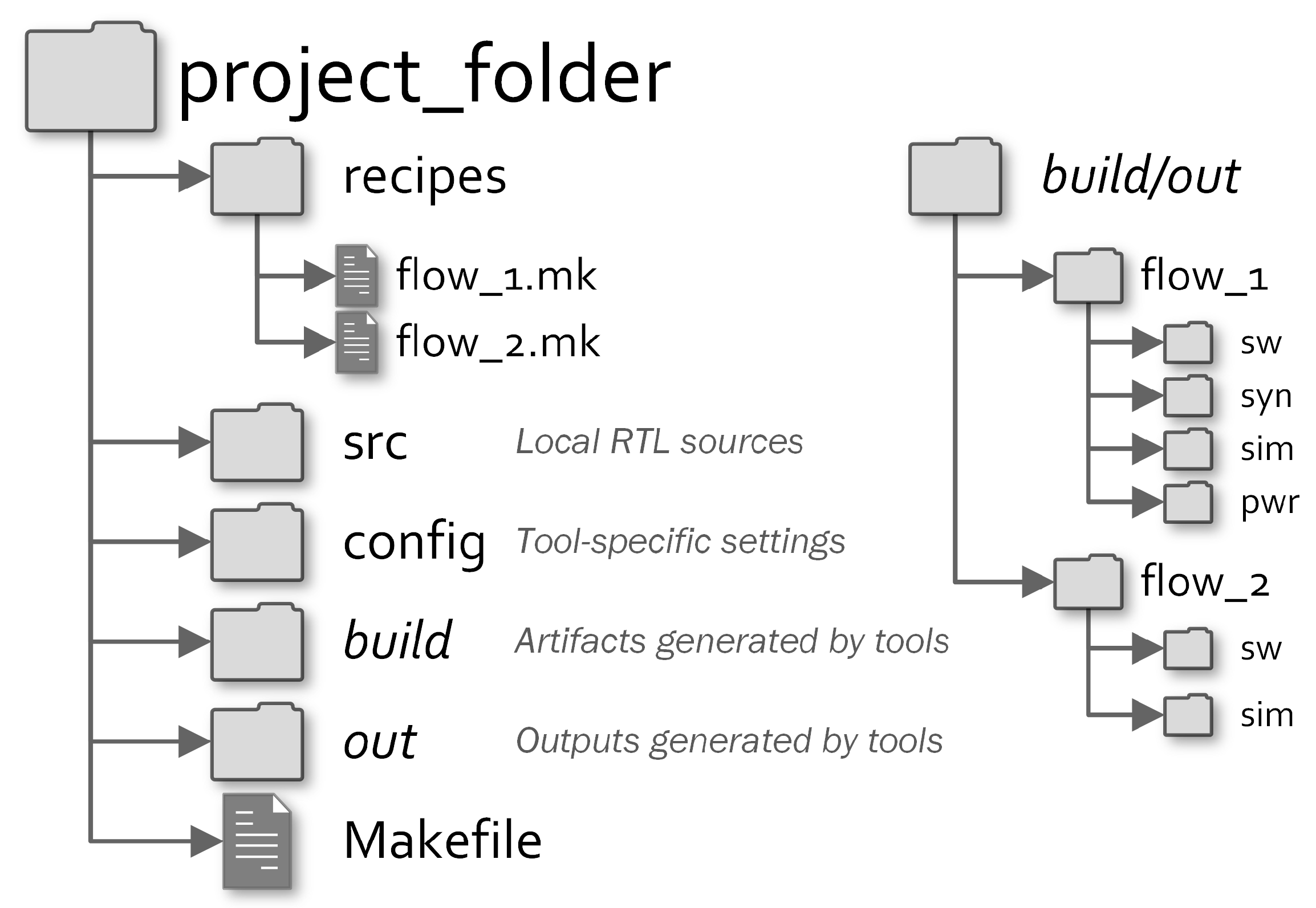
2.1. Workflow Customisation: Projects
- HDL files to include into the workflow.
- applications to compile for generating ROMs or initializing RAMs.
- hardware modules to synthesize.
- how many parametrized simulations to validate different SoC configurations.
- to perform power analysis for evaluating the power consumption in each simulated scenario.
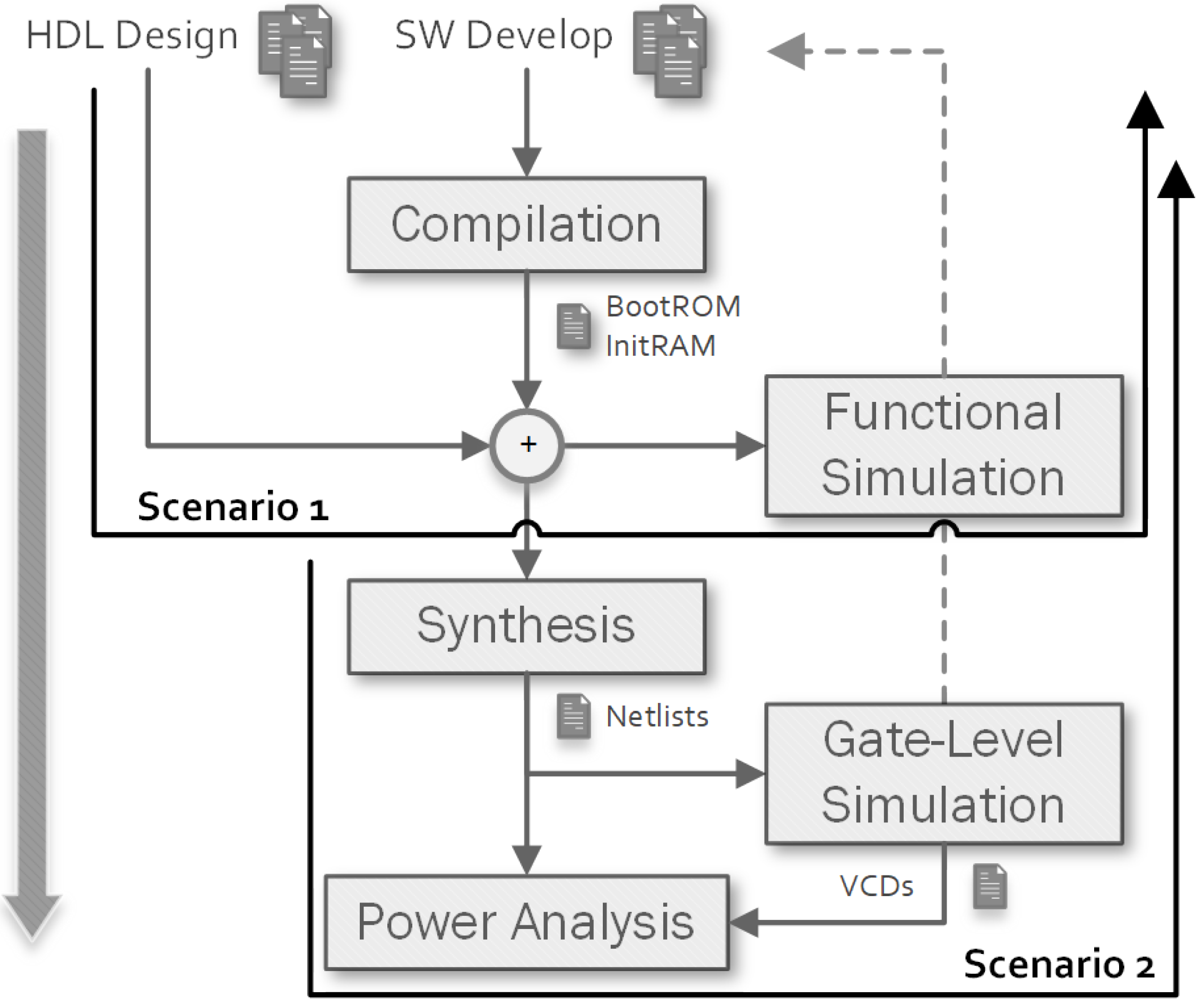
- Functional verification: it may compile some applications and then perform RTL simulations to verify the functionality of both hardware and software.
- Post-Synthesis verification: it may compile some applications used to stimulate the netlist of the RTL modules synthesised using the requested technology library. After that, it performs a timing gate-level simulation of the system to verify constraints and perform a cycle-true power consumption analysis. Furthermore, post-layout (for ASIC-based flows) and post-routing (for FPGA-based flows) netlists can be simulated.
2.2. Underlying Makefile System
|
- SW: can be set to cxx to enable compilation with RISC-V GNU Toolchain.
- SIM: can be set to questa to enable the simulation with Mentor QuestaSIM.
- SYN: can be set to dc to enable the synthesis with Synopsys Design Compiler.
- PWR: can be set to pt to enable the power analysis with Synopsys PrimeTime.
|
3. Tool Handlers
3.1. Software Tool Handler
3.1.1. Make Targets
- sw-<target>: starts the compilation of the specific target.
- sw-<target>-recompile: removes the generated output files and causes the recompilation of the modified sources to update the resulting image.
- sw-<target>-dump: after compilation, it prints the objdump of the specified target.
- sw-<target>-clean: deletes the build directory and the generated output.
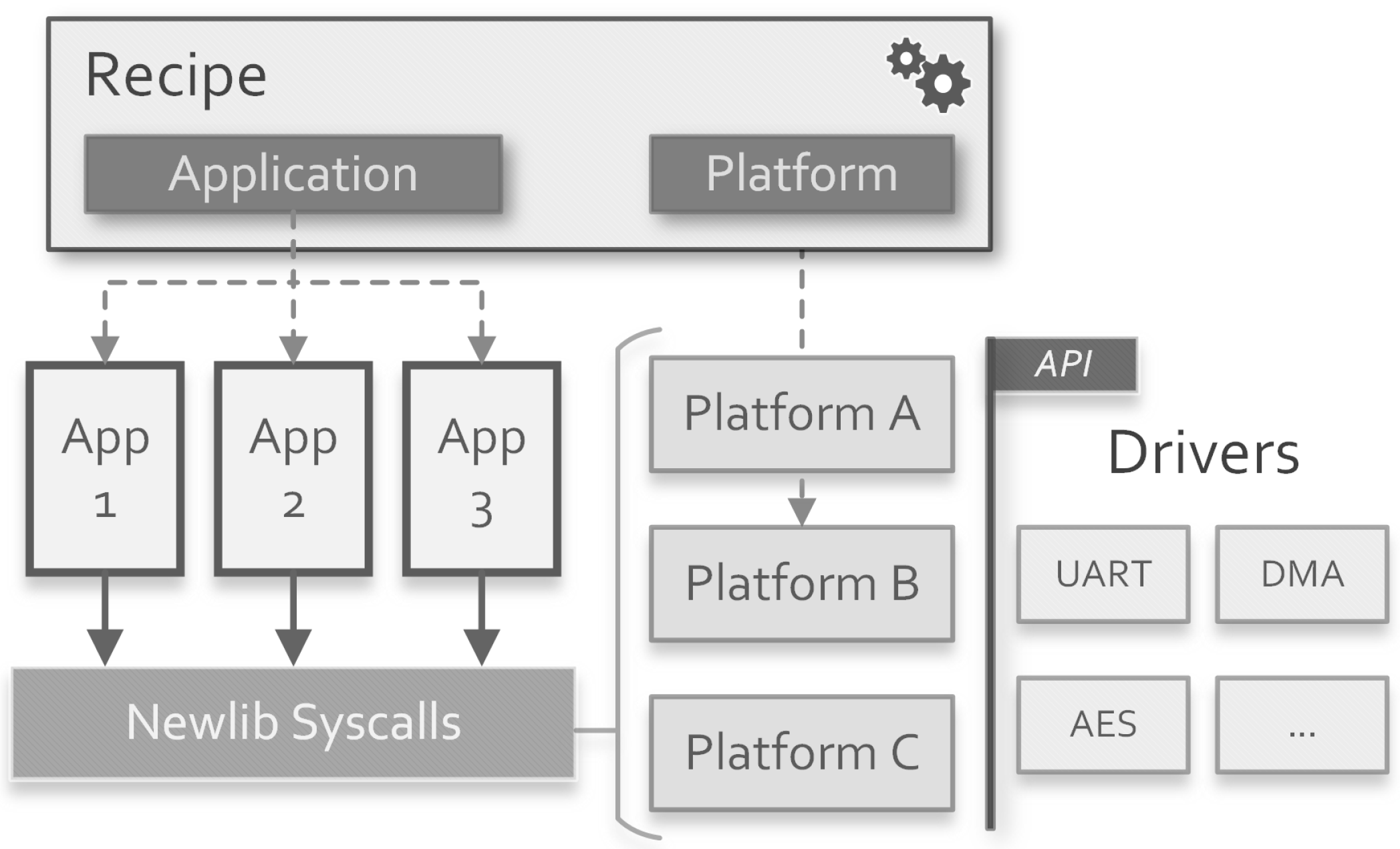
- SW_<target>_SDK: it specifies the SDK to use for compilation. Up to now, only a baremetal SDK is integrated within the framework. The actual compilation is performed by a sub-invocation of make into the desired software application directory using its own build system. In this way, any other SDK tool that produces ELF images as output can be included into the framework.
- SW_<target>_TYPE: can be bin, rom or ram. Binary output is desired to load the application on the target platform. ROM output generates a synthesizable SystemVerilog read-only memory. RAM output generates a simulation-only memory initialized with the application code.
- SW_<target>_MEMNAME: in case of rom or ram output, it specifies the name of the generated SystemVerilog module. This is desired to correctly instantiate the memory in the SoC.
3.1.2. Baremetal SDK
- SW_<target>_BAREMETAL_APP: used to select an available application located into the baremetal SDK directory.
- SW_<target>_BAREMETAL_ARCH: used to select the Application Binary Interface (ABI) string of the compiled image. It can be [soft|hard][32|64].
- SW_<target>_BAREMETAL_PLATFORM: used to select an available platform which provides the linker script, initialize the drivers, and redefines part of the Newlib syscalls.
- SW_<target>_BAREMETAL_DEFINES: a list of C defines passed to the compiler to customize the build process.
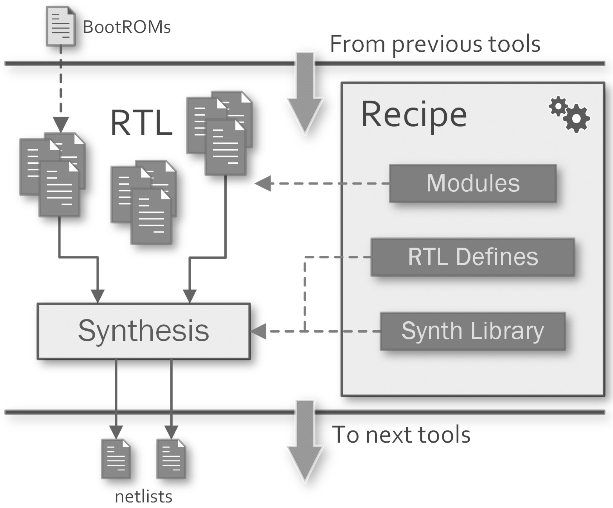
3.2. Synthesis Tool Handler
Make Targets
- syn-<target>: starts the synthesis process for the module <target>.
- syn-<target>-gui: starts the Graphical User Interface (GUI) of the third-party tool for the module <target>.
- syn-<target>-clean: deletes the build directory and the generated output.
- SYN_NETLIST_ANNOTATED: instruct the tool to generate the Standard Delay Format (SDF) files for the synthesised netlists.
- SYN_<target>_TOP: the name of the top-level module to synthesise the target.
- SYN_<target>_TOP_LIB: the name of the library where the top-level module of the target resides.
- SYN_<target>_RTL_DEFINES: can be used to provide per-target HDL defines to customize the RTL elaboration.
- SYN_<target>_REQUIRE_SW: if the requested target depends on a generated ROM from the software compilation step, this property can be set with the names of the related software targets. Make will ensure the dependency with the file generated by these targets.
- SYN_DC_LIB: relative path to the technology library to use for synthesis.
- SYN_DC_SETUP_FILE: the designer can pass a custom setup script to Design Compiler to customize more settings. It will be executed before the RTL analysis step.
- SYN_DC_SDC_FILES: can be used to provide constraints to the synthesis process of all targets.
- SYN_<target>_DC_SDC_FILES: can be used to provide per-target constraints to the synthesis process.
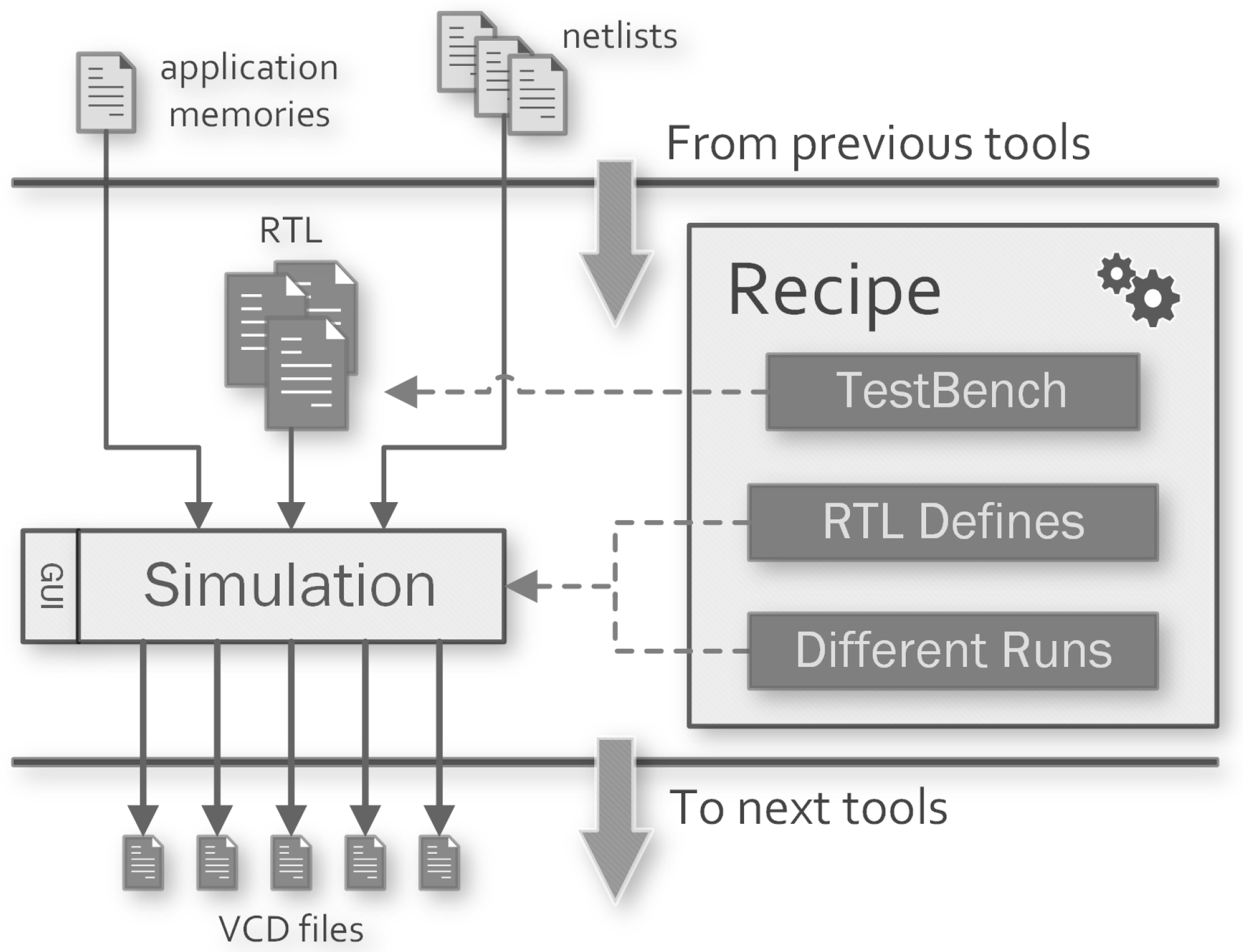
3.3. Simulation Tool Handler
Make Targets
- sim-<target>: after compiling and optimising the HDL sources, the simulation is executed in batch mode. Further commands can be provided to the simulator specifying the inclusion of a .do file with the SIM_CMD_FILE property.
- sim-<target>-gui: after compiling and optimizing the HDL sources, the GUI of the simulator tool is launched to continue the simulation manually. Further commands can be provided to the simulator specifying the inclusion of a .do file with the SIM_WAVE_FILE property, which is generally used to setup the Wave window of QuestaSIM.
- sim-<target>-compile: compile and optimise the HDL sources.
- sim-<target>-clean: deletes the build directory and the generated output files.
- SIM_TB: specifies the name of the testbench module to run for the simulation.
- SIM_TIMESCALE: sets the time unit and the time resolution for the simulation. A different timescale can be set for a specific target using the property SIM_<target>_TIMESCALE.
- SIM_RUNTIME: specifies the duration of the simulation, it can be set to all in order to wait for its end.
- SIM_RTL_DEFINES: list of defines passed to the compiler when compiling the functional HDL modules for all targets. Different defines can be specified for a specific target using the property SIM_<target>_RTL_DEFINES.
- SIM_SYN_DEFINES: list of defines passed to the compiler when compiling the synthesised HDL modules for all targets. Different defines can be specified for a specific target using the property SIM_<target>_SYN_DEFINES.
- SIM_VCD_MODULES: a list of modules whose nets activity will be saved in the compressed VCD file.
- SIM_VCD_ENTITIES: a list of entities whose activity will be saved in the compressed VCD file.
- SIM_<target>_REQUIRE_SW: list of software targets on which the simulation for <target> depends.
- SIM_<target>_REQUIRE_SYN: list of synthesis targets on which the simulation for <target> depends.
- SIM_DELETE_INTERMEDIATES: if enabled, at the end of each simulation, the compiled library is deleted to save space on disk. It can be useful when a lot of simulations which cannot share the compiled library (see next property) are performed.
- SIM_SHARE_LIB: if the design units does not need to be recompiled for each target, this property instructs the framework to compile the sources just once and share the library across the targets. It speeds up the simulation process and saves space on the disk when the designer sets up a lot of targets.
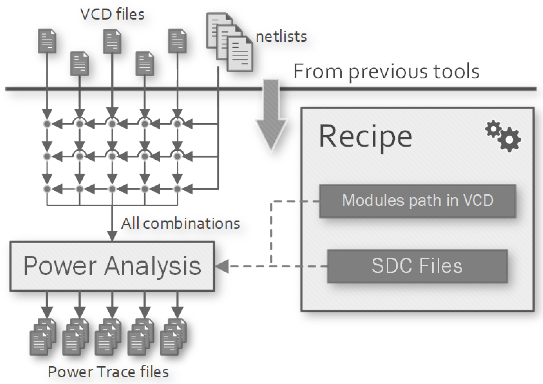
3.4. Power Analysis Tool Handler
Make Targets
- pwr-<target>: starts the power analysis process for the target.
- pwr-<target>-clean: deletes the build directory and the generated outputs of the target.
- PWR_DELETE_INPUTS: delete the input VCD file when power analysis completes to save space on disk.
- PWR_<syn_target>_NETLIST_PATH: identify the synthesised module <syn_target> into the VCD record.
3.5. Limited Power-Simulation Workflow Executor
|
- default: it runs software compilation and netlist synthesis before the sub-invocations of Make. Then, each sub-instance will compile the RTL sources in its build directory.
- shared library: it performs the compilation of the first simulation target before the sub-invocations of Make. Then, each sub-instance will create a symbolic link to the compiled library to perform the simulation.
- limit-pwr-sim-<sim>: waits on the limiting semaphore, runs Make on the pwr-<sim>, create a file to mark the run as completed and then posts on the semaphore.
- limit-pwr-sim-<sim>-clean: deletes the file used to mark the <sim> run as completed, to evaluate whether it should be updated through the sub-invocation of Make.
4. Use-Case: Performance Evaluation of an ECC Accelerator within a RISC-V-Based SoC
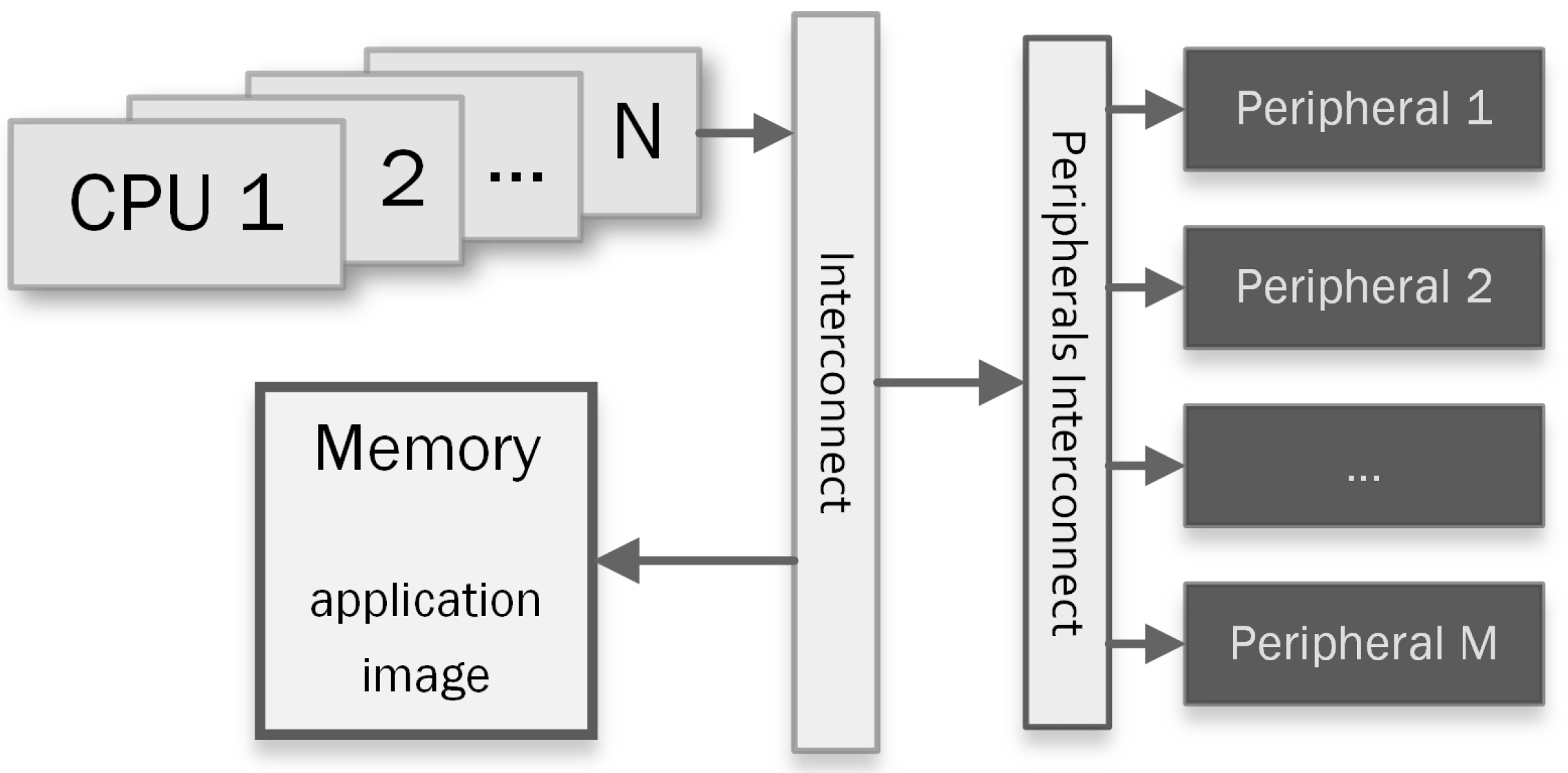
4.1. Use-Case System-on-Chip
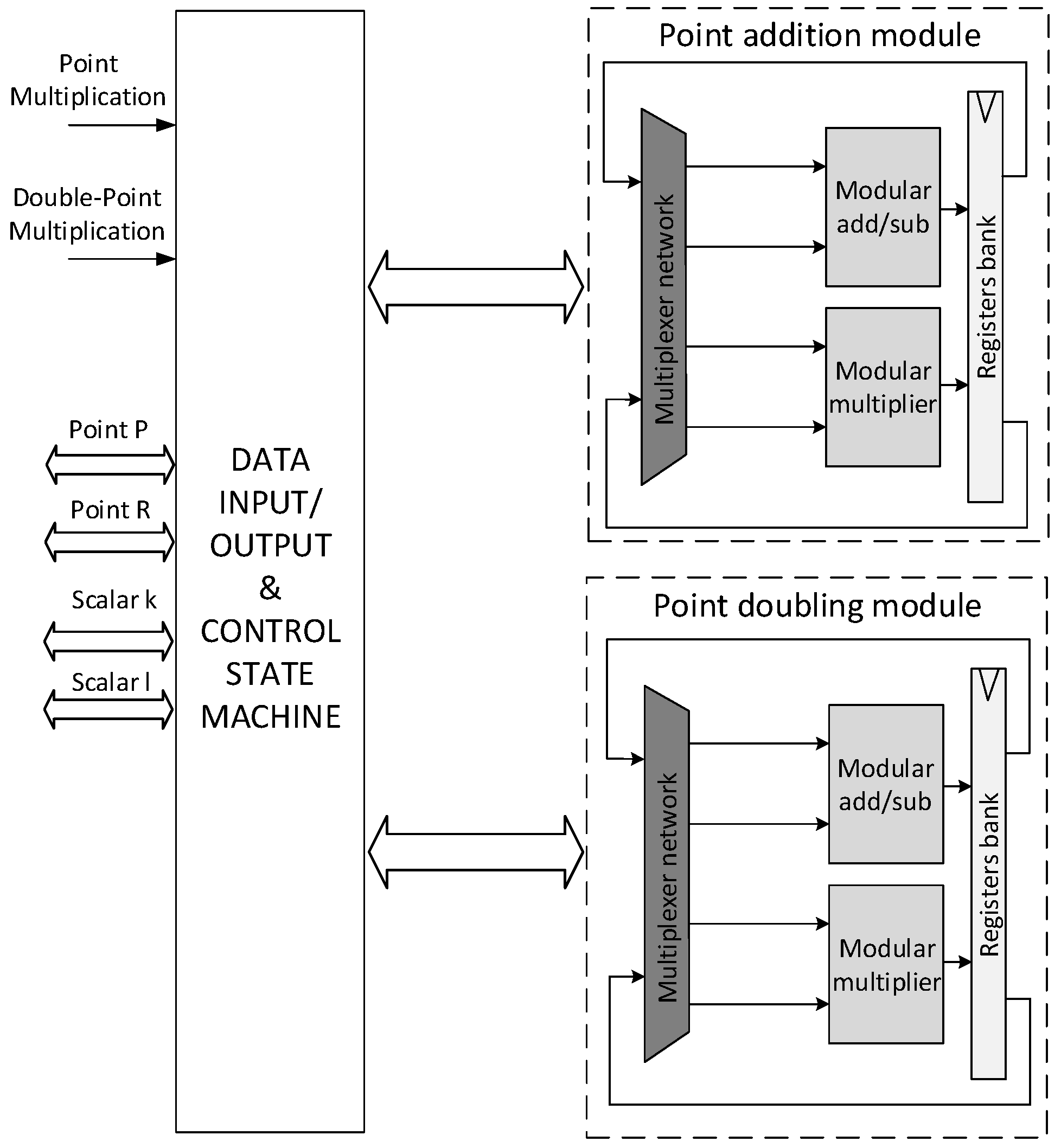
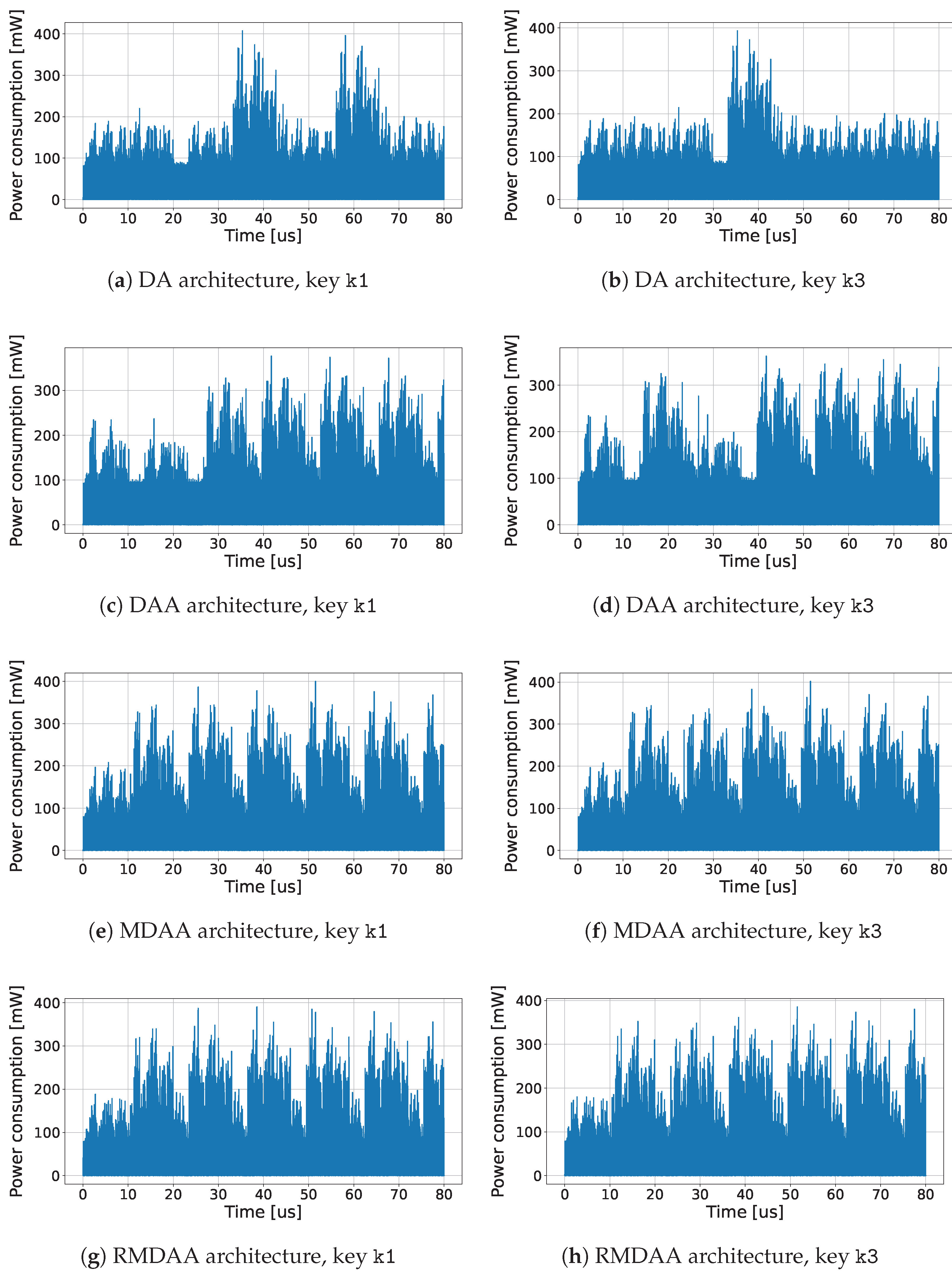
- DA: This configuration (already presented in [14]) performs PM using the standard Double-and-Add (DA) algorithm that is not resistant to SPA. This algorithm has no fixed latency, which depends on the value of the key k.
- DAA: This configuration (already presented in [14]) performs PM using the Double-and-Add-Always (DAA) algorithm, which is retained secure against SPA.
- MDAA: This configuration (already presented in [14]) performs PM using a Modified Double-and-Add-Always (MDAA) algorithm.
4.2. Recipe Configuration
|
|
|
|
|
|
4.3. Performance Evaluation Results
5. Conclusions
Author Contributions
Funding
Conflicts of Interest
Abbreviations
| ABI | Application Binary Interface |
| AES | Advanced Encryption Standard |
| API | Application Program Interface |
| ASIC | Application Specific Integrated Circuit |
| AXI | Advanced eXtensible Interconnect |
| CPU | Central Processing Unit |
| DA | Double-and-Add |
| DAA | Double-and-Add-Always |
| DPA | Differential Power Analysis |
| DRC | Design Rule Check |
| ECC | Elliptic Curve Cryptography |
| ECDH | Elliptic Curve Diffie-Hellman |
| ECDSA | Elliptic Curve Digital Signature Algorithm |
| ELF | Executable and Linkable Format |
| EPI | European Processor Initiative |
| FPGA | Field Programmable Gate Array |
| GUI | Graphical User Interface |
| HAMMER | Highly Agile Masks Made Effortlessly from RTL |
| HDL | Hardware Description Language |
| HSM | Hardware Secure Module |
| ISA | Instruction Set Architecture |
| MDAA | Modified Double-and-Add-Always |
| MPSoC | Multi-Processor Systems-on-Chip |
| P&R | Place-and-Route |
| PDK | Process Development Kit |
| PM | Point Multiplication |
| RAM | Random-Access Memory |
| RMDAA | Randomized Modified Double-and-Add-Always |
| ROM | Read-Only Memory |
| RTL | Register Transfer Level |
| SCA | Side-Channel Attack |
| SDF | Standard Delay Format |
| SDK | Software-Development-Kit |
| SoC | System-on-Chip |
| SPA | Simple Power Analysis |
| VCD | Value Change Dump |
| VLSI | Very Large Scale Integration |
References
- Balkind, J.; Lim, K.; Schaffner, M.; Gao, F.; Chirkov, G.; Li, A.; Lavrov, A.; Nguyen, T.M.; Fu, Y.; Zaruba, F.; et al. BYOC: A “Bring Your Own Core” Framework for Heterogeneous-ISA Research. In Proceedings of the ASPLOS ’20—Twenty-Fifth International Conference on Architectural Support for Programming Languages and Operating Systems, Lausanne Switzerland, 16–20 March 2020; Association for Computing Machinery: New York, NY, USA, 2020; pp. 699–714. [Google Scholar] [CrossRef] [Green Version]
- Mittal, S.; Vetter, J.S. A Survey of CPU-GPU Heterogeneous Computing Techniques. ACM Comput. Surv. 2015, 47, 1–35. [Google Scholar] [CrossRef]
- Wolf, W.; Jerraya, A.A.; Martin, G. Multiprocessor System-on-Chip (MPSoC) Technology. IEEE Trans. Comput.-Aided Des. Integr. Circuits Syst. 2008, 27, 1701–1713. [Google Scholar] [CrossRef]
- Balkind, J.; McKeown, M.; Fu, Y.; Nguyen, T.; Zhou, Y.; Lavrov, A.; Shahrad, M.; Fuchs, A.; Payne, S.; Liang, X.; et al. OpenPiton: An Open Source Manycore Research Framework. SIGARCH Comput. Archit. News 2016, 44, 217–232. [Google Scholar] [CrossRef] [Green Version]
- Waterman, A.; Asanovic, K. (Eds.) The RISC-V Instruction Set Manual, Volume I: User-Level ISA, Document Version 20191213; RISC-V Foundation: San Francisco, CA, USA, 2019. [Google Scholar]
- Nannipieri, P.; Di Matteo, S.; Zulberti, L.; Albicocchi, F.; Saponara, S.; Fanucci, L. A RISC-V Post Quantum Cryptography Instruction Set Extension for Number Theoretic Transform to Speed-Up CRYSTALS Algorithms. IEEE Access 2021, 9, 150798–150808. [Google Scholar] [CrossRef]
- Chen, W.; Ray, S.; Bhadra, J.; Abadir, M.; Wang, L. Challenges and Trends in Modern SoC Design Verification. IEEE Des. Test 2017, 34, 7–22. [Google Scholar] [CrossRef]
- Zulberti, L.; Nannipieri, P.; Fanucci, L. A Script-Based Cycle-True Verification Framework to Speed-Up Hardware and Software Co-Design of System-on-Chip exploiting RISC-V Architecture. In Proceedings of the 2021 16th International Conference on Design Technology of Integrated Systems in Nanoscale Era (DTIS), Montpellier, France, 28–30 June 2021; pp. 1–6. [Google Scholar] [CrossRef]
- Bash. by Free Software Foundation. Available online: https://www.gnu.org/software/bash (accessed on 11 November 2022).
- Spike RISC-V ISA Simulator. Available online: https://github.com/riscv-software-src/riscv-isa-sim (accessed on 11 November 2022).
- Sarti, L.; Baldanzi, L.; Crocetti, L.; Carnevale, B.; Fanucci, L. A Simulated Approach to Evaluate Side Channel Attack Countermeasures for the Advanced Encryption Standard. In Proceedings of the 2018 14th Conference on Ph.D. Research in Microelectronics and Electronics (PRIME), Prague, Czech Republic, 2–5 July 2018; pp. 77–80. [Google Scholar] [CrossRef]
- Adegbija, T.; Rogacs, A.; Patel, C.; Gordon-Ross, A. Microprocessor Optimizations for the Internet of Things: A Survey. IEEE Trans. Comput.-Aided Des. Integr. Circuits Syst. 2018, 37, 7–20. [Google Scholar] [CrossRef] [Green Version]
- Nannipieri, P.; Matteo, S.D.; Baldanzi, L.; Crocetti, L.; Zulberti, L.; Saponara, S.; Fanucci, L. VLSI Design of Advanced-Features AES Cryptoprocessor in the Framework of the European Processor Initiative. IEEE Trans. Very Large Scale Integr. (VLSI) Syst. 2022, 30, 177–186. [Google Scholar] [CrossRef]
- Di Matteo, S.; Baldanzi, L.; Crocetti, L.; Nannipieri, P.; Fanucci, L.; Saponara, S. Secure Elliptic Curve Crypto-Processor for Real-Time IoT Applications. Energies 2021, 14, 4676. [Google Scholar] [CrossRef]
- Hoffmann, A.; Kogel, T.; Nohl, A.; Braun, G.; Schliebusch, O.; Wahlen, O.; Wieferink, A.; Meyr, H. A novel methodology for the design of application-specific instruction-set processors (ASIPs) using a machine description language. IEEE Trans. Comput.-Aided Des. Integr. Circuits Syst. 2001, 20, 1338–1354. [Google Scholar] [CrossRef]
- Kinsy, M.A.; Pellauer, M.; Devadas, S. Heracles: A Tool for Fast RTL-Based Design Space Exploration of Multicore Processors. In Proceedings of the FPGA ’13—ACM/SIGDA International Symposium on Field Programmable Gate Arrays, Monterey, CA, USA, 11–13 February 2013; Association for Computing Machinery: New York, NY, USA, 2013; pp. 125–134. [Google Scholar] [CrossRef] [Green Version]
- Genko, N.; Atienza, D.; De Micheli, G.; Benini, L. Feature-NoC emulation: A tool and design flow for MPSoC. IEEE Circuits Syst. Mag. 2007, 7, 42–51. [Google Scholar] [CrossRef] [Green Version]
- de Micheli, G.; Benini, L. Networks on Chip: A New Paradigm for Systems on Chip Design. In Proceedings of the DATE ’02—Conference on Design, Automation and Test in Europe, Paris, France, 4–8 March 2002; IEEE Computer Society: Washington, DC, USA, 2002; p. 418. [Google Scholar]
- Pani, D.; Palumbo, F.; Raffo, L. A fast MPI-based parallel framework for cycle-accurate HDL multi-parametric simulations. Int. J. High Perform. Syst. Archit. 2010, 2, 187–202. [Google Scholar] [CrossRef]
- Wang, S.; Possignolo, R.T.; Skinner, H.B.; Renau, J. LiveHD: A Productive Live Hardware Development Flow. IEEE Micro 2020, 40, 67–75. [Google Scholar] [CrossRef]
- Tagliavini, G.; Rossi, D.; Marongiu, A.; Benini, L. Synergistic HW/SW Approximation Techniques for Ultralow-Power Parallel Computing. IEEE Trans. Comput.-Aided Des. Integr. Circuits Syst. 2018, 37, 982–995. [Google Scholar] [CrossRef] [Green Version]
- HAMMER: Highly Agile Masks Made Effortlessly from RTL. By UC Berkeley Architecture Research. Available online: https://github.com/ucb-bar/hammer (accessed on 11 November 2022).
- Chipyard Framework. By UC Berkley Architecture Research. Available online: https://github.com/ucb-bar/chipyard (accessed on 11 November 2022).
- European Processor Initiative. Available online: https://www.european-processor-initiative.eu (accessed on 11 November 2022).
- seL4 Microkernel. A Series of LF Projects, LLC. Available online: https://sel4.systems (accessed on 11 November 2022).
- Zephyr Project. A Linux Foundation Project. Available online: https://www.zephyrproject.org (accessed on 1 November 2022).
- Yocto Project. A Linux Foundation Collaborative Project. Available online: https://www.yoctoproject.org (accessed on 11 November 2022).
- Newlib C standard Library. Maintained by Red Hat. Available online: https://sourceware.org/newlib (accessed on 11 November 2022).
- Zaruba, F.; Benini, L. The Cost of Application-Class Processing: Energy and Performance Analysis of a Linux-Ready 1.7-GHz 64-Bit RISC-V Core in 22-nm FDSOI Technology. IEEE Trans. Very Large Scale Integr. (VLSI) Syst. 2019, 27, 2629–2640. [Google Scholar] [CrossRef]
- NIST, F. FIPS 186-4–Digital Signature Standard (DSS). 2013. Available online: https://csrc.nist.gov/publications/detail/fips/186/4/final (accessed on 11 November 2022).
- Möller, B. Parallelizable elliptic curve point multiplication method with resistance against side-channel attacks. In Information Security, Proceedings of the International Conference on Information Security, Sao Paulo, Brazil, 30 September–2 October 2002; Springer: Berlin/Heidelberg, Germany, 2002; pp. 402–413. [Google Scholar]
- Giraud, C.; Verneuil, V. Atomicity improvement for elliptic curve scalar multiplication. In Smart Card Research and Advanced Application, Proceedings of the International Conference on Smart Card Research and Advanced Applications, Passau, Germany, 14–16 April 2010; Springer: Berlin/Heidelberg, Germany, 2010; pp. 80–101. [Google Scholar]
- Dupuy, W.; Kunz-Jacques, S. Resistance of randomized projective coordinates against power analysis. In Cryptographic Hardware and Embedded Systems—CHES 2005, Proceedings of the International Workshop on Cryptographic Hardware and Embedded Systems, Edinburgh, UK, 29 August–1 September 2005; Springer: Berlin/Heidelberg, Germany, 2005; pp. 1–14. [Google Scholar]


| ECC PM Config | Area (kGE) | Latency (us) | Power (mW) | Peak (mW) |
|---|---|---|---|---|
| DA | 247.92 | 32.256 | 57.1 | 407.1 |
| DAA | 253.88 | 36.880 | 69.7 | 394.0 |
| MDAA | 248.05 | 36.848 | 68.1 | 401.3 |
| RMDAA | 249.80 | 36.848 | 68.6 | 398.5 |
Publisher’s Note: MDPI stays neutral with regard to jurisdictional claims in published maps and institutional affiliations. |
© 2022 by the authors. Licensee MDPI, Basel, Switzerland. This article is an open access article distributed under the terms and conditions of the Creative Commons Attribution (CC BY) license (https://creativecommons.org/licenses/by/4.0/).
Share and Cite
Zulberti, L.; Di Matteo, S.; Nannipieri, P.; Saponara, S.; Fanucci, L. A Script-Based Cycle-True Verification Framework to Speed-Up Hardware and Software Co-Design: Performance Evaluation on ECC Accelerator Use-Case. Electronics 2022, 11, 3704. https://doi.org/10.3390/electronics11223704
Zulberti L, Di Matteo S, Nannipieri P, Saponara S, Fanucci L. A Script-Based Cycle-True Verification Framework to Speed-Up Hardware and Software Co-Design: Performance Evaluation on ECC Accelerator Use-Case. Electronics. 2022; 11(22):3704. https://doi.org/10.3390/electronics11223704
Chicago/Turabian StyleZulberti, Luca, Stefano Di Matteo, Pietro Nannipieri, Sergio Saponara, and Luca Fanucci. 2022. "A Script-Based Cycle-True Verification Framework to Speed-Up Hardware and Software Co-Design: Performance Evaluation on ECC Accelerator Use-Case" Electronics 11, no. 22: 3704. https://doi.org/10.3390/electronics11223704
APA StyleZulberti, L., Di Matteo, S., Nannipieri, P., Saponara, S., & Fanucci, L. (2022). A Script-Based Cycle-True Verification Framework to Speed-Up Hardware and Software Co-Design: Performance Evaluation on ECC Accelerator Use-Case. Electronics, 11(22), 3704. https://doi.org/10.3390/electronics11223704