Article

A Script-Based Cycle-True Verification Framework to Speed-Up Hardware and Software Co-Design: Performance Evaluation on ECC Accelerator Use-Case

Department of Information Engineering, University of Pisa, Via G. Caruso, 16, 56122 Pisa, Italy
*
Author to whom correspondence should be addressed.
These authors contributed equally to this work.
Electronics 2022, 11(22), 3704; https://doi.org/10.3390/electronics11223704
Submission received: 11 October 2022 / Revised: 4 November 2022 / Accepted: 9 November 2022 / Published: 12 November 2022
(This article belongs to the Special Issue VLSI Design, Testing, and Applications)

Abstract

:
Digital designs complexity has exponentially increased in the last decades. Heterogeneous Systems-on-Chip integrate many different hardware components which require a reliable and scalable verification environment. The effort to set up such environments has increased as well and plays a significant role in digital design projects, taking more than 50% of the total project time. Several solutions have been developed with the goal of automating this task, integrating various steps of the Very Large Scale Integration design flow, but without addressing the exploration of the design space on both the software and hardware sides. Early in the co-design phase, designers break down the system into hardware and software parts taking into account different choices to explore the design space. This work describes the use of a framework for automating the verification of such choices, considering both hardware and software development flows. The framework automates compilation of software, cycle-true simulations and analyses on synthesised netlists. It accelerates the design space exploration exploiting the GNU Make tool, and we focus on ensuring consistency of results and providing a mechanism to obtain reproducibility of the design flow. In design teams, the last feature increases cooperation and knowledge sharing from single expert to the whole team. Using flow recipes, designers can configure various third-party tools integrated into the modular structure of the framework, and make workflow execution customisable. We demonstrate how the developed framework can be used to speed up the setup of the evaluation flow of an Elliptic-Curve-Cryptography accelerator, performing post-synthesis analyses. The framework can be easily configured taking approximately 30 min, instead of few days, to build up an environment to assess the accelerator performance and its resistance to simple power analysis side-channel attacks.

1. Introduction

The complexity of digital design has increased a lot in last decades with heterogeneous architectures [1,2] and Multi-Processor Systems-on-Chips (MPSoCs) in general [3,4]. Nowadays challenges lie in optimising each module of a heterogeneous system and its integration within it. The design space that System-on-Chip (SoC) designers have to explore is very wide and includes the addition of functionalities by selecting available modules, and the firmware or software application tuning. The evaluation of hardware and software co-design choices allows the selection of the best candidate configuration for given requirements.
The RISC-V [5] open-source Instruction Set Architectures (ISAs), together with its open-source implementations, have boosted co-design methodologies aimed to produce custom hardware with dedicated ISA extensions [6]. Thus, from development to tape-out, designers have to dedicate a substantial amount of time to setup all tools needed to execute the entire workflow for their projects. With these systems, the verification process is a very expensive task [7] and represents a large portion of the total cost of the project.
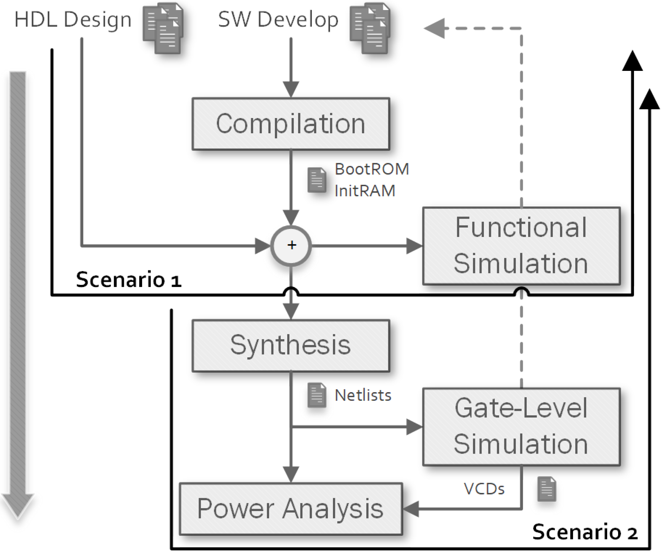
The target of this work, which extends our previous publication [8], is the workflow of heterogeneous digital designs described in Figure 1. The development cycle of these designs is very long. The most prominent hardware/software partitioning solutions must be evaluated in term of performance, power consumption, and area utilisation. The power analysis can be performed only at the final stage, when hardware and software development paths are integrated. Hardware emulation can integrate the two separated paths in advance, however, it does not validate any hardware-dependent results, only the functionality.
For simple designs, workflow automation is conducted by using scripting languages, such as Bash [9]. But this approach is not scalable and is prone to errors due to manual modification of scripts. To ensure the consistency of the results, the workflow should implement dependency checks between tools, and should support the integration of different tools. Furthermore, since these workflows take up to several hours to complete, it is important that their automation mechanisms do not produce undesirable results due to errors in the environment itself. Our contribution focuses on the automation of design and verification workflows. Designers should not take care of tool configurations, inter-tool dependencies, and automation scripts. We want to eliminate the time overheads caused by these tasks and their tendency to be error prone when performed manually.
We propose an automating framework implementing hardware and software compilation techniques to accelerate the design space exploration of hardware/software co-designs in heterogeneous digital systems. It makes the customization of state-of-art design tools simple and efficient by interacting with it at a single and high-level of abstraction provided by our Makefile-based infrastructure. The aim of the proposed framework is to improve the productivity of designers of such complex systems. In a team, designers use their knowledge to customise a particular portion of the design flow, benefiting from other contributions. Our framework provides a standardised interface to adapt the workflow to the needs of the designer, while not limiting the capabilities of state-of-the-art tools, such as compilers, Hardware Description Language (HDL) simulators, synthesisers, and others. All the different hardware and software choices identified during the co-design phase of the project can be evaluated by setting up multiple workflow executions with different parameters. We also integrate into the framework the RISC-V toolchain, an emerging state-of-the-art technology that is pervading every field of application. To adequately prepare the framework to use cases characterised by cycle-accurate simulations used to gather a more accurate time-based power consumption, we focused its development on post-synthesis analyses and related tools. Design space explorations following accurate power consumption and area occupancy evaluations cannot be done with faster but less detailed tools, such as emulators or ISA simulators [10]. Our framework can be exploited when designing robust systems against Side-Channel Attack (SCA) [11], ultra-low-power and heterogeneous [12], or space-grade SoCs, where the target technology, in both Application Specific Integrated Circuit (ASIC) or Field Programmable Gate Array (FPGA) development flows, determines the time-based power consumption and area occupancy outcomes. It has been used in [6] to assist the design of a Post-Quantum Cryptography ISA extension for RISC-V, and in [13] to collect post-synthesis results of a cryptographic hardware accelerator for Advanced Encryption Standard (AES). To describe our work, we present an use case in which the performance of an Elliptic Curve Cryptography (ECC) accelerator [14] are assessed using the proposed framework, showing how the complexity of the design flow is reduced thanks to the automation provided. The implemented workflow is important in security applications where SCAs could exploit physical vulnerabilities to obtain information on secret keys used for cryptographic operations.

1.1. Related Works

From all the flow optimisation works for heterogeneous digital systems design found in literature [15,16,17,18,19,20,21], Highly Agile Masks Made Effortlessly from RTL (HAMMER) [22] is one of the projects closest to our work, as it focuses on workflow automation. It is used within the Chipyard framework [23] to automate its Very Large Scale Integration (VLSI) design flow. The generation of scripts and collaterals is done by exploiting Pyhton and Make, and it can be integrated by implementing a set of Application Program Interfaces (APIs) to run the steps of the flow. It is focused on the hardware design space exploration, i.e., synthesis, Place-and-Route (P&R), Design Rule Check (DRC), gate-level simulation, and power analysis and does not provide software support in it. Its execution is demanded to an executable separated from GNU Make, hence it cannot trace dependencies between each tool using the Make dependency check system. Furthermore, it does not provide a way to run the tools in the flow multiple times with different configurations. Our framework is better integrated with the GNU Make tool, providing finer control on the execution of the various design tools and on their output files. It integrates also the bare-metal software design flow, which is required when designing SoC solutions composed of processors (based on RISC-V ISA in our case) and peripherals.

1.2. Outline

In Section 2 we describe the proposed co-design verification framework: how it can be used and configured. In Section 3 we go into the various parts of the framework, describing all its configuration options. In Section 4 we describe the use-case workflow for the post-synthesis performance evaluation of an ECC accelerator that will be integrated into the Hardware Secure Module (HSM) of the European Processor Initiative (EPI) [24]. In the end, we discuss the conclusions in Section 5.

2. Our Script-Based Verification Framework

This section describes the main aspects of the framework in order to explain how the designers can exploit it during their works. Figure 2 illustrates the four main components of the framework: projects, tool handlers, Register Transfer Level (RTL) library and Software-Development-Kits (SDKs). Tool handlers are scripts written in Make syntax that execute an associated third-party tool, and are organized by type (software compilers, simulators, synthesisers, and power analysers). Up to now, there are four types of tools, each one driven by the associated tool handler that customize its behaviour with project configurations:
  • Software Compilation: generates synthesizable Read-Only Memorys (ROMs) or simulation-only initialized Random-Access Memorys (RAMs) through RISC-V GNU Toolchain 12.1.0.
  • RTL Synthesis: provides the netlists used in timing verification and power analysis through Synopsis Design Compiler 2022.03.
  • RTL Simulation: performs functional and gate-level simulations (depending on whether the synthesis has been performed or not) through Mentor QuestaSIM 21.3.
  • Power Analysis: provides cycle-true power consumption profiles using simulation results and synthesized netlists through Synopsis PrimeTime 2022.03.
Other tools can be integrated into the framework (such as VCS or Verilator simulator, Synplify synthesis tool and Clang compiler) thanks to the standardised interface represented by the naming of Make variables and the paths of generated files, which the tool handlers use to communicate with each other. The requested tool handlers define a set of targets that perform the design tasks. They are invoked by the framework using one of the two workflow executors implementing a particular behaviour to conduct the design flow:
  • Default: during parallel executions, Make decide how to schedule the invocation of all targets the selected tool handlers have defined.
  • Limited Power-Analysis: targets defined by simulation and power analysis tool handlers are grouped together to constraint their concurrent execution, thus reducing the number of Value Change Dump (VCD) files residing on the disk simultaneously. With many parallel simulations, this solution can limit disk usage.

2.1. Workflow Customisation: Projects

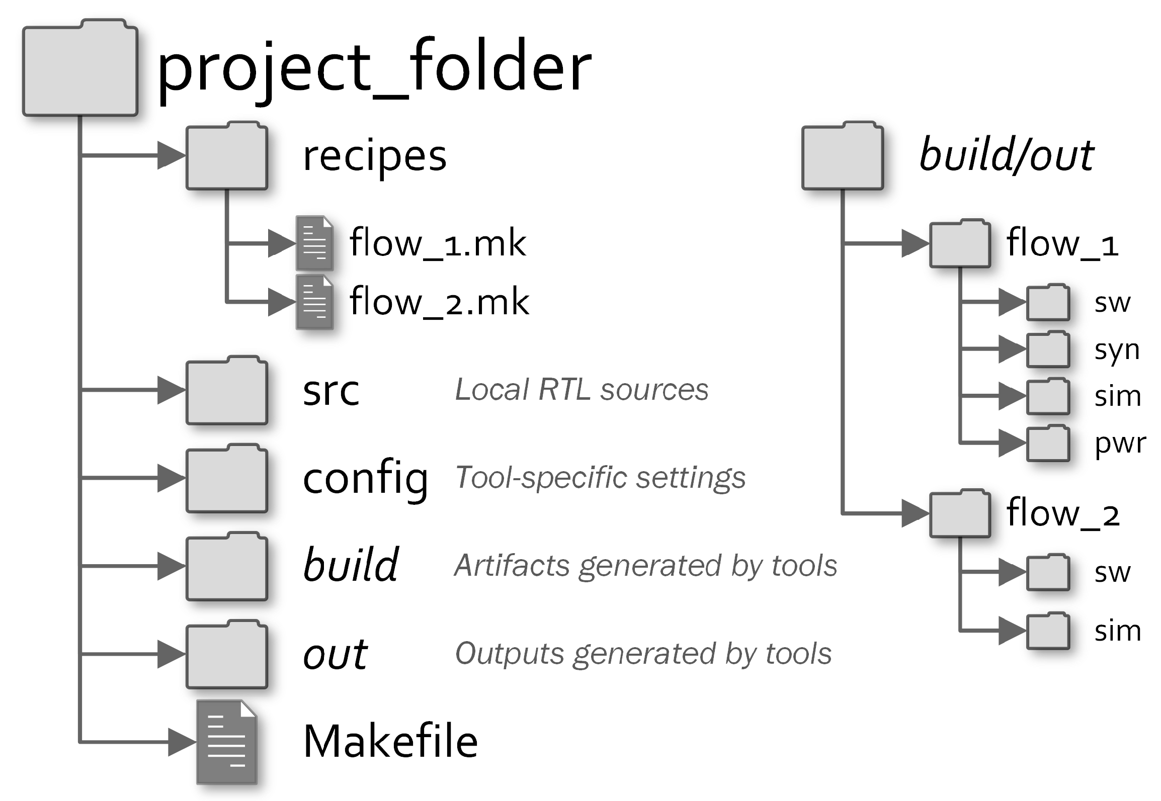
Figure 3 illustrates that each project is composed of flow recipes, RTL sources, tool-related configuration files and the main Makefile. Also flow recipes are written in Make syntax and define the variables, referred to as properties henceforth, which customise the execution of the tools. Designers select the tools to run at Make invocation by writing the flow recipes of the project. To increase the productivity of design space exploration, recipes and tools can be executed in parallel also respecting the dependency constraints. During the execution of the workflow, the framework generates the output artefacts of each recipe in the relevant folder, where it in turn calls up the required tools in separate folders.
Sharing only flow recipes and related configuration files, each designer of a team, software or hardware, can test its system with contributions from the others. The automation mechanisms makes the evaluation of each optimisation choice simple, reliable, and reproducible, because using the same flow recipe gives the same results. Customizing flow recipes, designers can choose:
  • HDL files to include into the workflow.
  • applications to compile for generating ROMs or initializing RAMs.
  • hardware modules to synthesize.
  • how many parametrized simulations to validate different SoC configurations.
  • to perform power analysis for evaluating the power consumption in each simulated scenario.
As reported in Figure 4, by configuring the flow recipes the workflow accomplishes the following verification scenarios:
  • Functional verification: it may compile some applications and then perform RTL simulations to verify the functionality of both hardware and software.
  • Post-Synthesis verification: it may compile some applications used to stimulate the netlist of the RTL modules synthesised using the requested technology library. After that, it performs a timing gate-level simulation of the system to verify constraints and perform a cycle-true power consumption analysis. Furthermore, post-layout (for ASIC-based flows) and post-routing (for FPGA-based flows) netlists can be simulated.

2.2. Underlying Makefile System

The framework is started by invoking Make inside the project directory (i.e., Figure 3) where the primary makefile is located. Make takes the instructions to generate the targets from a file called Makefile. The targets are files generated by the execution of a list of commands called recipe. The generation of some targets may depend on some other files, which can be source files located on the disk or can be represented in turn by other Make targets. The dependencies of a target are called prerequisites. For example, a target A which has got two targets B and C as prerequisites is not generated until they have been satisfied. Thus, the recipes of B and C are executed if they are missing or if they are older than the prerequisites on which they in turn depend. This mechanism ensures that the generated files are consistent with all the sources on which they depend directly or indirectly. Each target in the makefile can be defined with this syntax:
  • target … : prerequisites …     
  •     recipe     
  •     …     
The Makefile of the project includes the entry script which starts the execution of the framework. After loading the selected flow recipe, it loads the requested tool handlers that define the targets performing the tasks of the workflow. Designers can set the property related to a tool type with the name of the desired tool:
  • SW: can be set to cxx to enable compilation with RISC-V GNU Toolchain.
  • SIM: can be set to questa to enable the simulation with Mentor QuestaSIM.
  • SYN: can be set to dc to enable the synthesis with Synopsys Design Compiler.
  • PWR: can be set to pt to enable the power analysis with Synopsys PrimeTime.
The Make targets defined by each tool handler are responsible to run the design flow. Make ensures dependencies between them, allowing the workflow to be executed without any user interaction. By simply invoking make, the designer lets the requested workflow executor handle the tool invocations and carry out the whole workflow. He can also run only a step by invoking make on the related target (e.g., make sw to compile all applications).
The execution of the desired tools is obtained by setting them as prerequisites of the default Make target default, which starts when the designer invokes make without targets. For example, a flow recipe that defines a workflow composed of all four steps, the dependencies between the tools could be described by this pseudo-Make syntax:
  • default: sw syn sim pwr
  • sw:  sw-app1 sw-app2
  • syn: syn-mod1 syn-mod2 syn-mod3
  • sim: sim-run1 sim-run2
  • pwr: pwr-run1-mod1 pwr-run1-mod2 pwr-run1-mod3
  •      pwr-run2-mod1 pwr-run2-mod2 pwr-run2-mod3
  •  
  • sw-app1: app1.mem <other deps>
  • app1.mem: <src deps>
  •     <commands>
  • […]
  •  
  • syn-mod1: mod1.v <other deps>
  • mod1.v: <hdl deps>
  •     <commands>
  • […]
  •  
  • sim-run1: run1-dump1.vcd <other deps>
  • run1-dump.vcd: app1.mem mod1.v <hdl deps>
  •     <commands>
  • […]
  •  
  • pwr-run1-mod1: run1-mod1-power.out <other deps>
  • run1-mod1-power.out: dump1.vcd mod1.v <other deps>
  •     <commands>
  • […]
The four tools are instructed to build two application images (sw-app1, sw-app2), generate three synthesised netlists (syn-mod1, syn-mod2, syn-mod3), run two simulation (sim-run1, sim-run2), and perform six power analyses (all pwr-sim*-mod*). Each target lists its dependencies as prerequisites and defines the commands to launch for carrying out its part of the design flow.

3. Tool Handlers

In this section we will describe the most important configuration options provided by the various tool handlers of the framework. The workflow execution can be customized according to the user needs by setting these properties as described in the next paragraphs.

3.1. Software Tool Handler

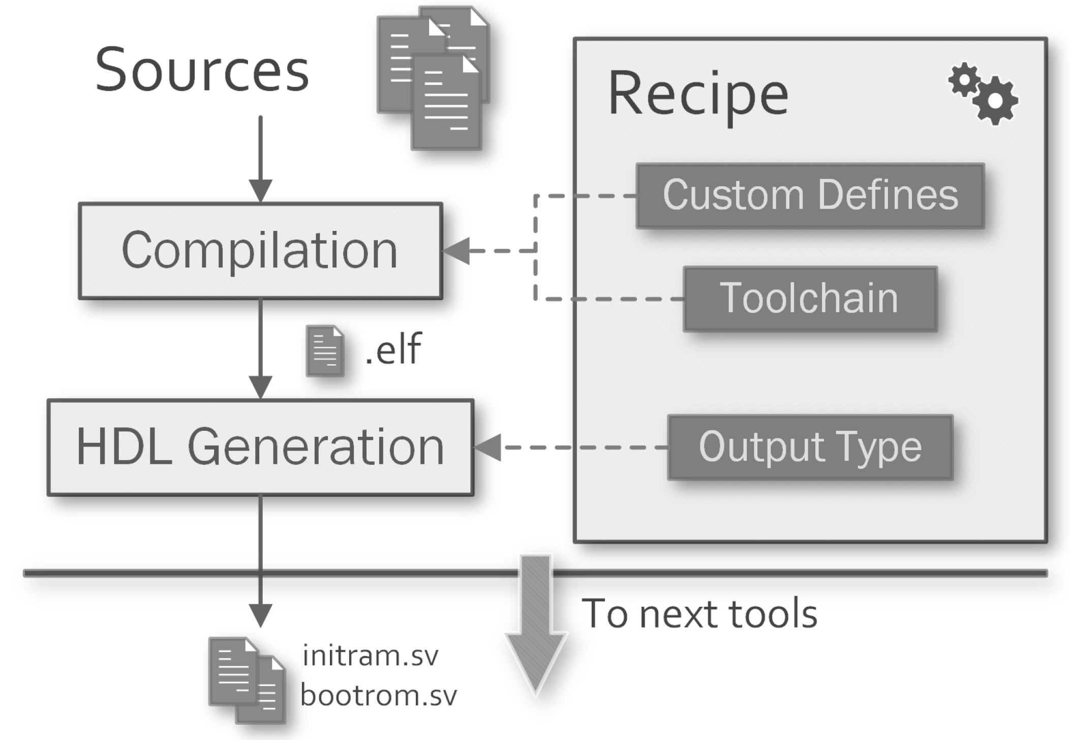
Software compilation is the first step of the workflow. As described in Figure 5, it generates the Executable and Linkable Format (ELF) images of the applications to run using the desired toolchain. The ELF images can be used to load the applications into the real platform or can be dumped for debugging purposes.
The compilation process can be customized with the flow recipe using C/C++ defines and it can feed the successive phases of the workflow converting the built images into an HDL ROM or a simulation-only initialized RAM. These files can be used to synthesise the boot ROMs of the SoC or to run the application within the simulator. The compilation can be performed with different toolchains by setting the SW property to the desired one. Using cxx, the targets are compiled with the GCC Toolchain architectures using the tool handler we wrote. The designer can define multiple targets to generate more than one application image, this can be useful for projects containing several ROMs or initialized RAMs. The idea behind this is to support a multi-ISA heterogeneous architecture in which the binaries can be compiled with different toolchain settings.

3.1.1. Make Targets

For each requested application, defined with the SW_TARGETS property, the framework generates a sw-<target> Make target on which sw depends on, along with others utility targets:
  • sw-<target>: starts the compilation of the specific target.
  • sw-<target>-recompile: removes the generated output files and causes the recompilation of the modified sources to update the resulting image.
  • sw-<target>-dump: after compilation, it prints the objdump of the specified target.
  • sw-<target>-clean: deletes the build directory and the generated output.
The compilation process can be customized with several properties that can be provided to the handler:
  • SW_<target>_SDK: it specifies the SDK to use for compilation. Up to now, only a baremetal SDK is integrated within the framework. The actual compilation is performed by a sub-invocation of make into the desired software application directory using its own build system. In this way, any other SDK tool that produces ELF images as output can be included into the framework.
  • SW_<target>_TYPE: can be bin, rom or ram. Binary output is desired to load the application on the target platform. ROM output generates a synthesizable SystemVerilog read-only memory. RAM output generates a simulation-only memory initialized with the application code.
  • SW_<target>_MEMNAME: in case of rom or ram output, it specifies the name of the generated SystemVerilog module. This is desired to correctly instantiate the memory in the SoC.

3.1.2. Baremetal SDK

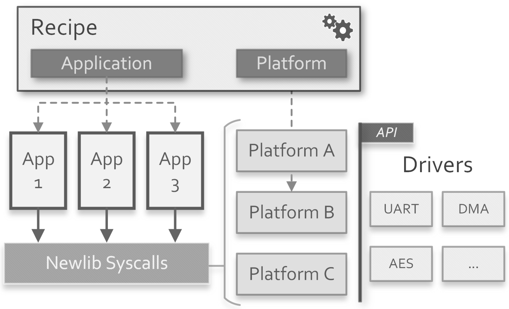
Applications can be compiled using different SDKs and build systems. The compilation process is accomplished through a sub-invocation of Make (or another build utility) into the desired project of the SDK. The reason behind this is to keep compatibility with many software environments available online, for example the ones based on seL4 Microkernel [25], Zephyr Project [26] and Yocto Project [27]. In this work, we set up a baremetal SDK based on the Newlib C standard library [28] provided by the RISC-V GCC Toolchain.
As shown in Figure 6, the SDK is composed of three parts: the platform-independent code, composed by drivers and syscalls redefinitions; the platform-dependent code, which initializes peripherals using drivers and provides the linker script; the applications, which use the Newlib interface and the API provided by drivers.
Each image compiled with the baremetal SDK can be customized using these properties provided by the framework:
  • SW_<target>_BAREMETAL_APP: used to select an available application located into the baremetal SDK directory.
  • SW_<target>_BAREMETAL_ARCH: used to select the Application Binary Interface (ABI) string of the compiled image. It can be [soft|hard][32|64].
  • SW_<target>_BAREMETAL_PLATFORM: used to select an available platform which provides the linker script, initialize the drivers, and redefines part of the Newlib syscalls.
  • SW_<target>_BAREMETAL_DEFINES: a list of C defines passed to the compiler to customize the build process.

3.2. Synthesis Tool Handler

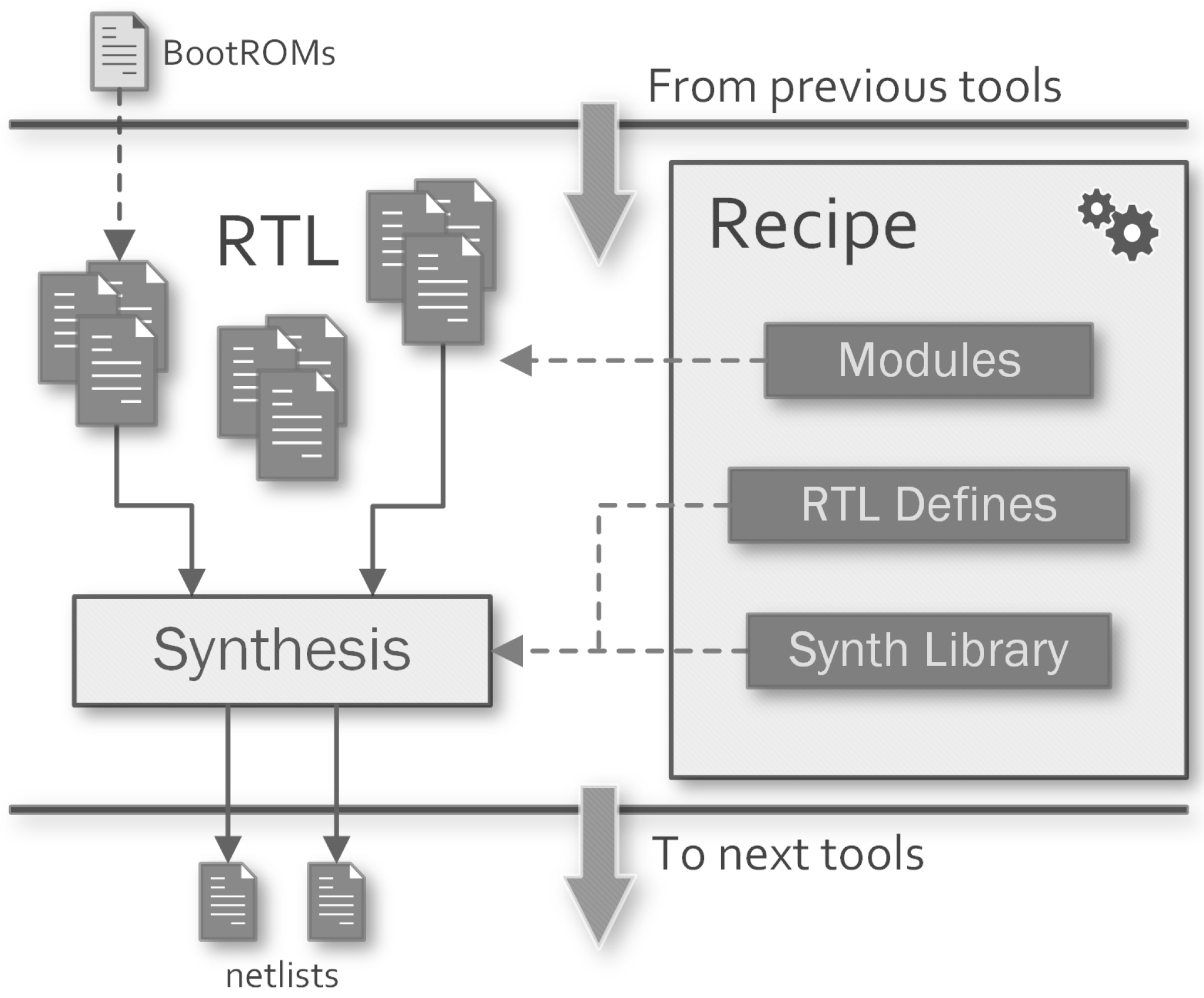
RTL synthesis can be performed to generate the netlist of different modules of the system using an available synthesis library. As illustrated in Figure 7, if previous tools provide any synthesisable sources (e.g., ROMs from software tool), this step is executed after their completion.
The synthesis can be performed with different tools setting the SYN property to the desired one. Using dc, the modules are synthesised with Synopsys Design Compiler using the tool handler we wrote. Into the flow recipe there can be defined multiple targets to generate more than one synthesised netlist. The idea behind this is to perform a mixed functional and gate-level simulation to evaluate the post-synth performances of the desired modules, using the stimulus given by the functional part of the simulated system.

Make Targets

For each module requested to be synthesised through the SYN_TARGETS property, the framework generates a syn-<target> Make target on which syn depends on, along with a cleaning target:
  • syn-<target>: starts the synthesis process for the module <target>.
  • syn-<target>-gui: starts the Graphical User Interface (GUI) of the third-party tool for the module <target>.
  • syn-<target>-clean: deletes the build directory and the generated output.
The synthesis process can be customized with several properties that can be provided to the handler:
  • SYN_NETLIST_ANNOTATED: instruct the tool to generate the Standard Delay Format (SDF) files for the synthesised netlists.
  • SYN_<target>_TOP: the name of the top-level module to synthesise the target.
  • SYN_<target>_TOP_LIB: the name of the library where the top-level module of the target resides.
  • SYN_<target>_RTL_DEFINES: can be used to provide per-target HDL defines to customize the RTL elaboration.
  • SYN_<target>_REQUIRE_SW: if the requested target depends on a generated ROM from the software compilation step, this property can be set with the names of the related software targets. Make will ensure the dependency with the file generated by these targets.
  • SYN_DC_LIB: relative path to the technology library to use for synthesis.
  • SYN_DC_SETUP_FILE: the designer can pass a custom setup script to Design Compiler to customize more settings. It will be executed before the RTL analysis step.
  • SYN_DC_SDC_FILES: can be used to provide constraints to the synthesis process of all targets.
  • SYN_<target>_DC_SDC_FILES: can be used to provide per-target constraints to the synthesis process.

3.3. Simulation Tool Handler

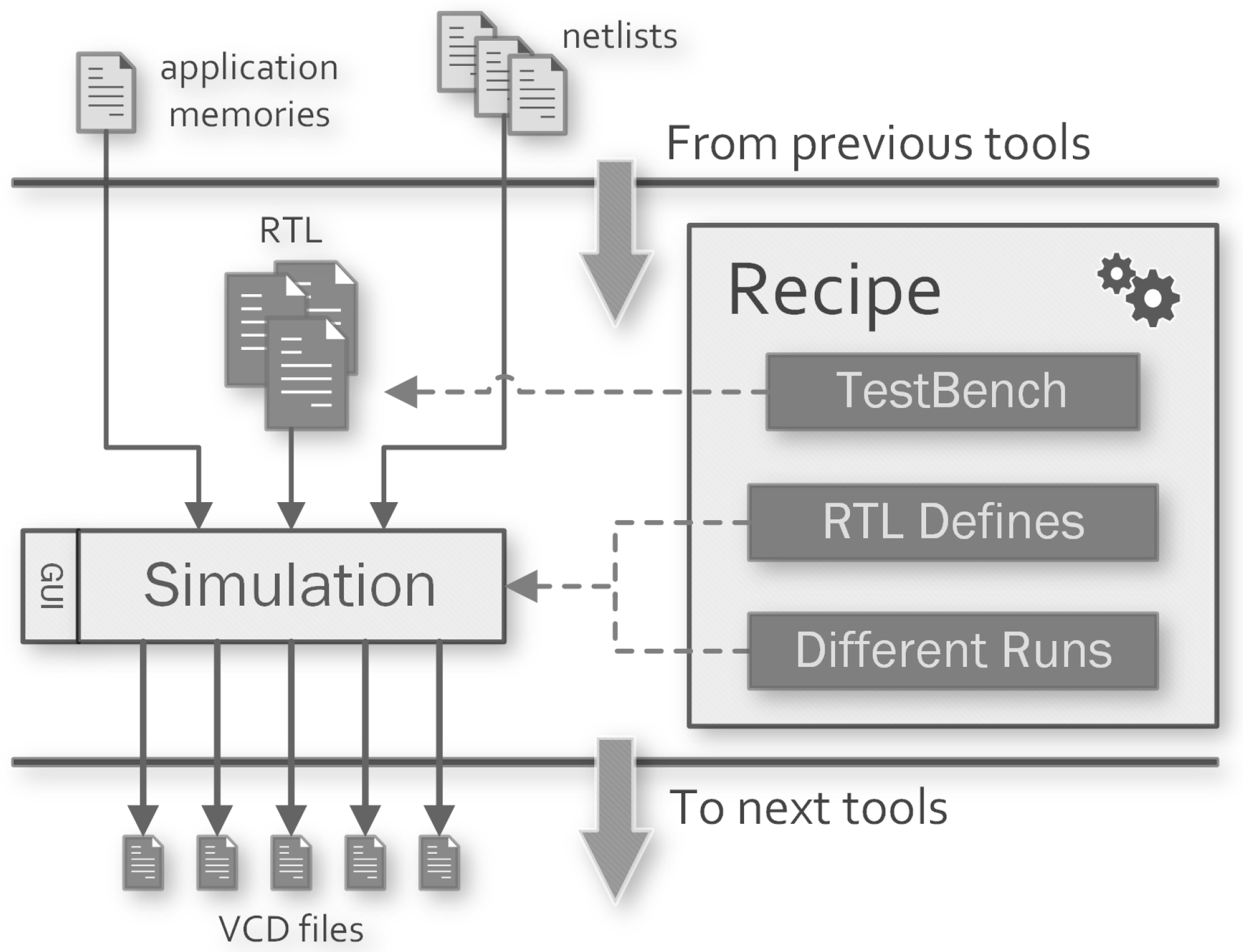
Functional and gate-level simulations are performed using the HDL modules provided by the framework library, the local sources and the modules generated by previous tools. As shown in Figure 8, different simulations can be started and customized to perform functional verification of the SoC starting the GUI or the batch simulation.
The designer can use this phase to provide VCD files for further evaluations with successive tools. The simulation step can be performed with different tools setting the SIM property to the desired one. Using questa the targets are simulated by Mentor QuestaSIM using the tool handler we wrote. Into the flow recipe there can be defined multiple targets to simulate testbenches with different parameters. The HDL outputs from the software compilation and the RTL synthesis steps are automatically added to the prerequisites of the simulation Make target to ensure their generation before the simulation begins.

Make Targets

For each simulation target defined through the SIM_TARGETS property, the framework generates a sim-<target> Make target on which sim depends on, along with others utility targets:
  • sim-<target>: after compiling and optimising the HDL sources, the simulation is executed in batch mode. Further commands can be provided to the simulator specifying the inclusion of a .do file with the SIM_CMD_FILE property.
  • sim-<target>-gui: after compiling and optimizing the HDL sources, the GUI of the simulator tool is launched to continue the simulation manually. Further commands can be provided to the simulator specifying the inclusion of a .do file with the SIM_WAVE_FILE property, which is generally used to setup the Wave window of QuestaSIM.
  • sim-<target>-compile: compile and optimise the HDL sources.
  • sim-<target>-clean: deletes the build directory and the generated output files.
SIM_CMD_FILE and SIM_WAVE_FILE properties are evaluated in the same manner by the simulator. They are kept separated to provide different behaviour for batch and GUI simulations.
Batch and GUI simulations can be customized with several properties that can be provided to the handler:
  • SIM_TB: specifies the name of the testbench module to run for the simulation.
  • SIM_TIMESCALE: sets the time unit and the time resolution for the simulation. A different timescale can be set for a specific target using the property SIM_<target>_TIMESCALE.
  • SIM_RUNTIME: specifies the duration of the simulation, it can be set to all in order to wait for its end.
  • SIM_RTL_DEFINES: list of defines passed to the compiler when compiling the functional HDL modules for all targets. Different defines can be specified for a specific target using the property SIM_<target>_RTL_DEFINES.
  • SIM_SYN_DEFINES: list of defines passed to the compiler when compiling the synthesised HDL modules for all targets. Different defines can be specified for a specific target using the property SIM_<target>_SYN_DEFINES.
  • SIM_VCD_MODULES: a list of modules whose nets activity will be saved in the compressed VCD file.
  • SIM_VCD_ENTITIES: a list of entities whose activity will be saved in the compressed VCD file.
  • SIM_<target>_REQUIRE_SW: list of software targets on which the simulation for <target> depends.
  • SIM_<target>_REQUIRE_SYN: list of synthesis targets on which the simulation for <target> depends.
  • SIM_DELETE_INTERMEDIATES: if enabled, at the end of each simulation, the compiled library is deleted to save space on disk. It can be useful when a lot of simulations which cannot share the compiled library (see next property) are performed.
  • SIM_SHARE_LIB: if the design units does not need to be recompiled for each target, this property instructs the framework to compile the sources just once and share the library across the targets. It speeds up the simulation process and saves space on the disk when the designer sets up a lot of targets.
In addition, there are dedicated properties for netlist optimisation and tool-dependent command-line arguments (e.g., vopt […] -sdftyp /dut/path=/sdf/path) that can be specified.

3.4. Power Analysis Tool Handler

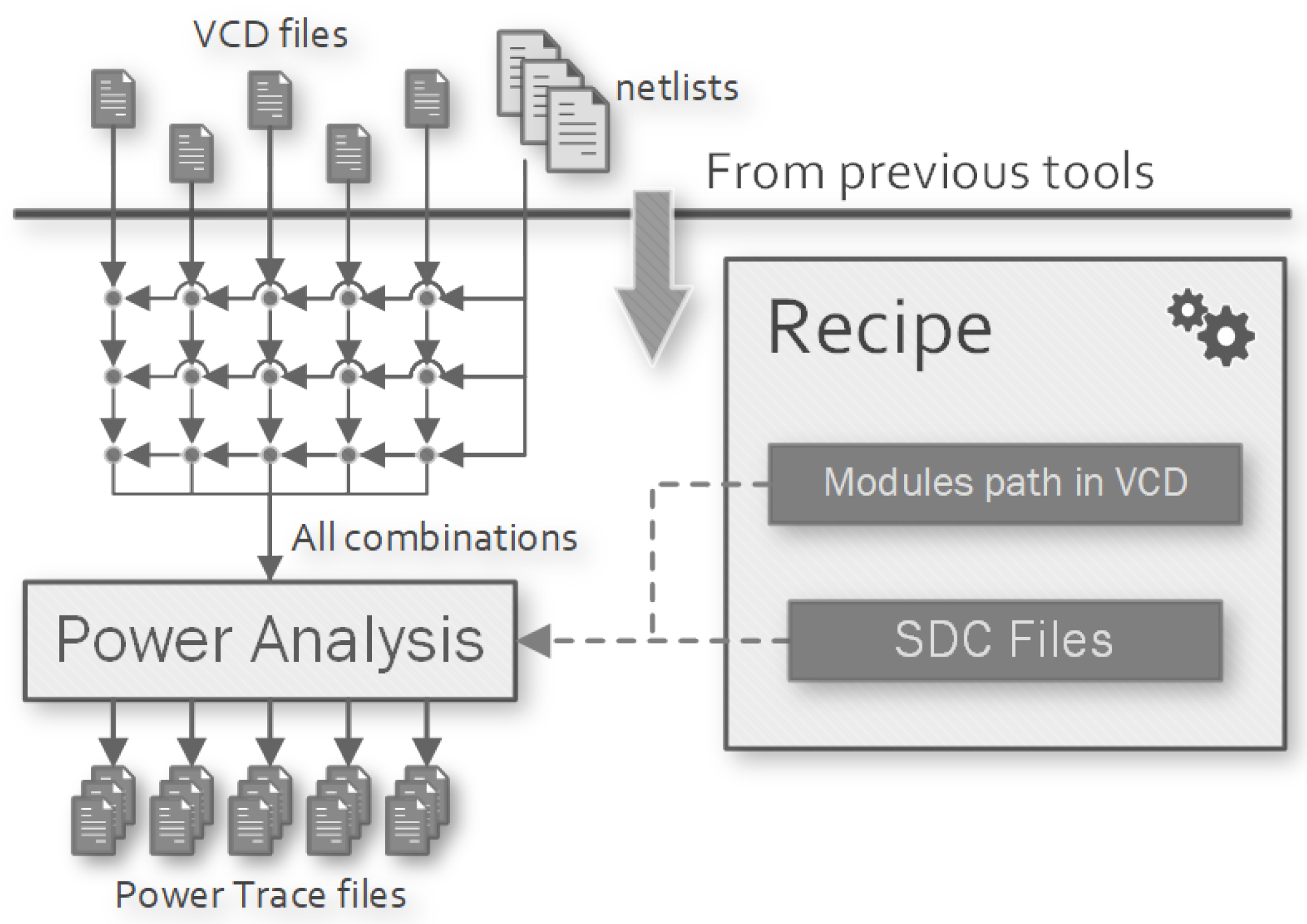
Power analysis is performed to provide an estimation of the time-based power consumption of the synthesised modules using their netlist, the synthesis library and all the VCD files generated by the simulations.
The power analysis step can be performed with different tools by setting the PWR property to the desired one. Using pt, the power consumption evaluation is done by Synopsys PrimeTime using the tool handler we wrote. The Make targets may not be defined into the flow recipe because they are generated automatically: one for each combination of synthesised module and simulation run, as shown in Figure 9. The VCD files generated by the simulator and the synthesised modules are automatically added to the prerequisites of the power analysis Make targets to ensure their generation before the analysis begins.

Make Targets

For each combination of simulation runs (SIM_TARGETS property) and synthesised modules (SYN_TARGETS property) on which they depends (defined by the SIM_<target>_ REQUIRE_SYN properties), the framework generates a pwr-<target> Make target (where <target> = <syn_target>-<sim_target>) on which pwr depends on, along with a cleaning target:
  • pwr-<target>: starts the power analysis process for the target.
  • pwr-<target>-clean: deletes the build directory and the generated outputs of the target.
Power analysis process can be customised with two properties that must be provided to the handler:
  • PWR_DELETE_INPUTS: delete the input VCD file when power analysis completes to save space on disk.
  • PWR_<syn_target>_NETLIST_PATH: identify the synthesised module <syn_target> into the VCD record.

3.5. Limited Power-Simulation Workflow Executor

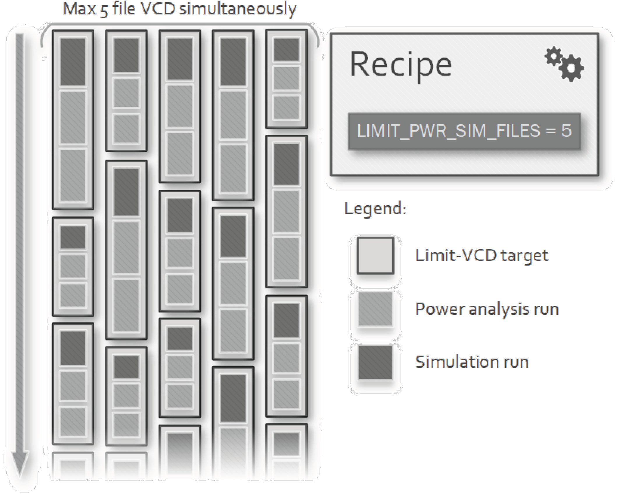
In complete workflows, when simulation and power analysis are requested, the generated VCD files can be very large and in case the recipes define several simulation targets, disk space could easily run out. The solution is to delete each VCD file as soon as it has been used by the power analysis tool. This cannot be easily done with the execution of the default Make target recipe, because the order in which the targets are executed when make is invoked with -j option is not defined. All simulations could be executed before running all the power analysis, ending up with a lot of VCD files. Even though the files are all deleted at the end of the workflow, the number of them on disk at the same time cannot be controlled. To accomplish this scenario, the designer must set the property WORKFLOW to limit-pwr-sim and define the property LIMIT_PWR_SIM_FILES = N. The framework will include the workflow executor we wrote that defines a limit-pwr-sim-<sim> target for each simulation run. They are generated specifically for grouping together the simulation and the power analysis targets related to the same VCD file.
The execution of its recipe performs a sub-invocation of the Make command with the specific pwr-<sim> target as argument, which then depends on all pwr-<sim>-* targets as described in Figure 10. This invocation is wrapped into a wait-post sequence on a semaphore file on the disk initialized with N to limit the sequences running simultaneously. In this way, only up to N simulation outputs can reside on disk at the same time. This number does not interfere with the limitation of parallel instances given by the set of *_PARALLEL properties, which are always respected. The Make recipe generated for simulation <sim> can be summarized by the following simplified version:
  • limit-pwr-sim-<sim>: $(LIMIT_VCD_DEPS)      
  •     $(limit-pwr-sim-semaphore) wait   
  •     $(MAKE) PWR_DELETE_INPUTS=yes pwr-<sim>   
  •     $(limit-pwr-sim-semaphore) post   
where limit-pwr-sim-semaphore is a shortcut for the execution of the bash script which handles the semaphore for this task. When Make is invoked with -jM option with M > N , only N spawned jobs can execute the pwr-<sim> target, the other ones must wait on the semaphore.
The limit-pwr-sim-<sim> targets must take care of dependency with the simulation targets to prevent a race condition within the sub-invocation of the make command. There could be multiple executions of the software or synthesis targets on which the simulation and the power analysis steps depends. Depending on the type of simulation performed, the dependencies are adjusted accordingly:
  • default: it runs software compilation and netlist synthesis before the sub-invocations of Make. Then, each sub-instance will compile the RTL sources in its build directory.
  • shared library: it performs the compilation of the first simulation target before the sub-invocations of Make. Then, each sub-instance will create a symbolic link to the compiled library to perform the simulation.
As the other tools, this one stores all the necessary files into its build directory and defines some Make targets: for each simulation run, this workflow executor generates a limit-pwr-sim-<sim> Make target on which limit-pwr-sim depends on, plus a cleaning target:
  • limit-pwr-sim-<sim>: waits on the limiting semaphore, runs Make on the pwr-<sim>, create a file to mark the run as completed and then posts on the semaphore.
  • limit-pwr-sim-<sim>-clean: deletes the file used to mark the <sim> run as completed, to evaluate whether it should be updated through the sub-invocation of Make.

4. Use-Case: Performance Evaluation of an ECC Accelerator within a RISC-V-Based SoC

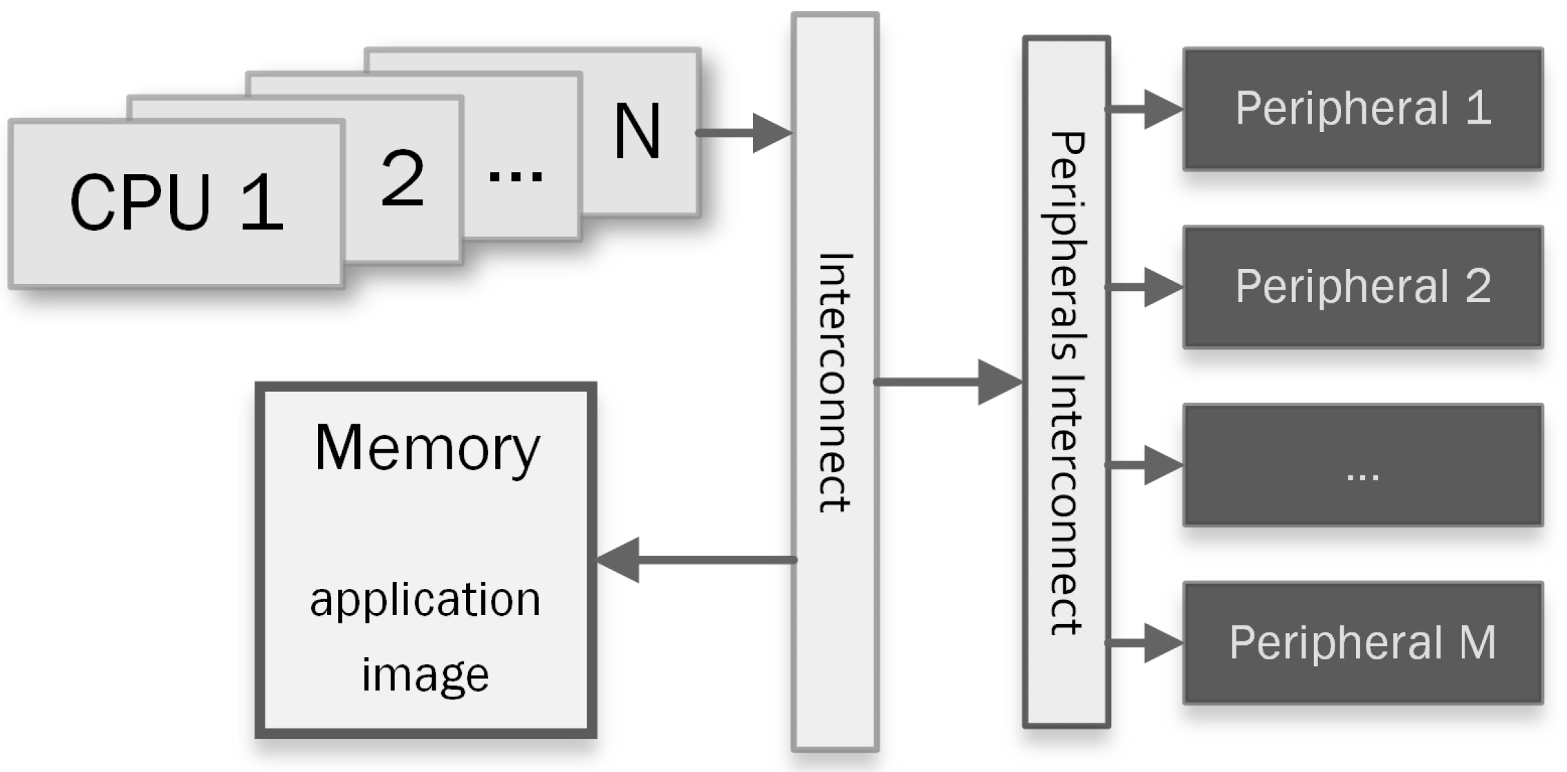
The use-case in Figure 11 schematizes the typical scenarios in which the proposed framework aids the design process.
They are composed of one or more Central Processing Units (CPUs), an interconnection mechanism, some peripherals, and the memories where the applications, executed during the simulation, reside. From this general scenario, we want to focus on the power consumption evaluation of some modules in the design, using different parameters to customize the analysis procedure. To further illustrate the framework features and prove the design productivity gain achieved with the aided workflow, we present a use-case example where the framework helps to set up the environment needed to obtain the desired result. The execution of the workflows described in next section has been performed on a computer equipped with two Intel(R) Xeon(R) E5-2650 v3 CPUs and 384 G i B of RAM running CentOS Linux 7.

4.1. Use-Case System-on-Chip

This section presents how the various parts of the framework have been used to perform the post-synthesis evaluation of a hardware accelerator for ECC. As reported in Section 1, such hardware module will be integrated into the Hardware Secure Module of the European Processor Initiative (EPI) chip and implemented in a 7 nm ARM® Artisan technology. The use of the framework has reduced the time spent on building up the design and verification environment to set up all the synthesis, simulations, and power analysis steps of the workflow. It has also permitted the evaluation of many simulations with different input data.
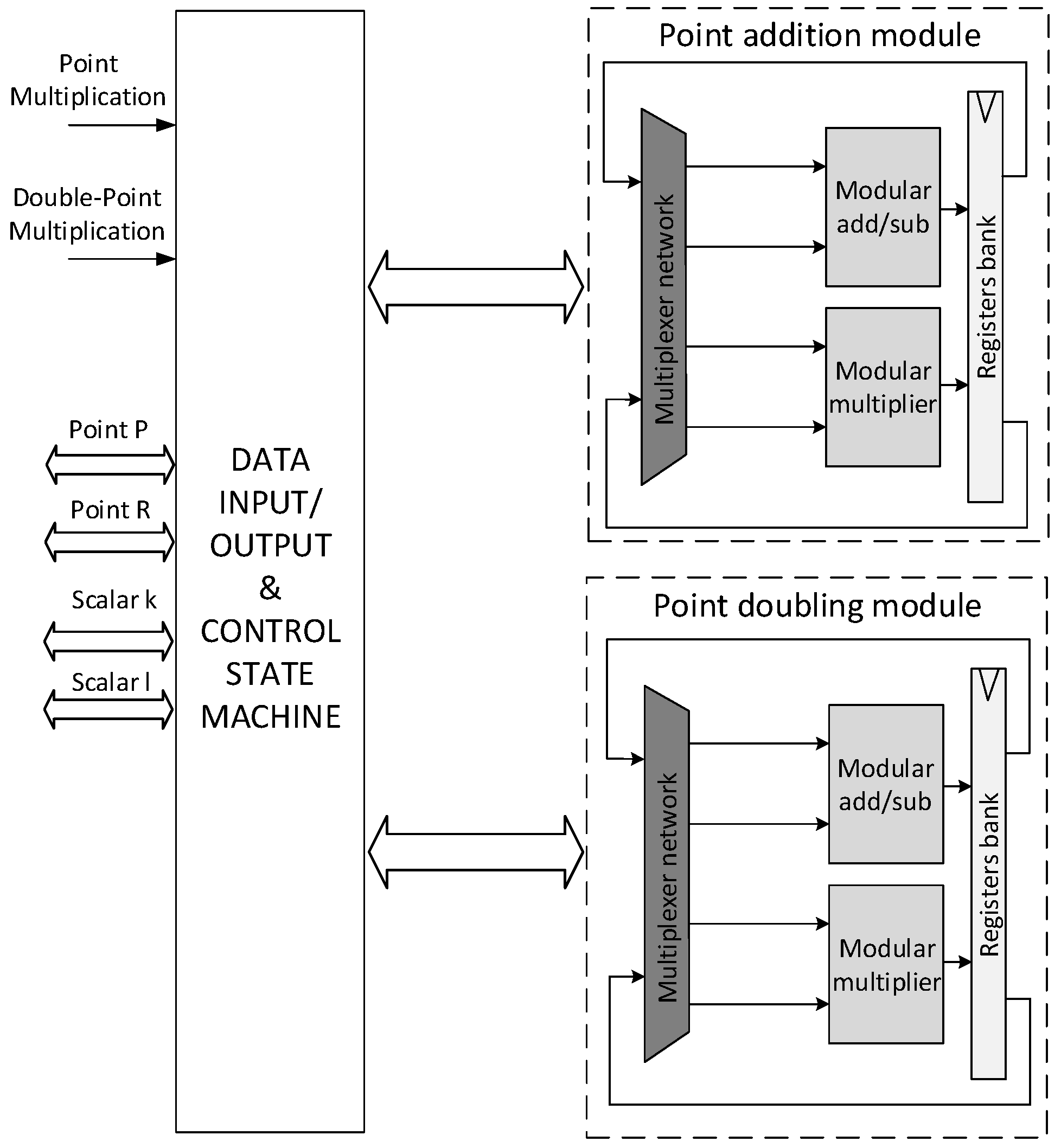
As shown in Figure 12, the simulations instantiate a SoC composed of a RISC-V CPU (64bit CVA6 by OpenHw Group [29]), an Advanced eXtensible Interconnect (AXI) communication network, a simulation-only RAM initialised with the binary of the application, and the hardware accelerator for ECC (henceforth ECC Core). The ECC Core under evaluation can be configured to support both the NIST P-256 and NIST P-521 elliptic curves [30], which are used to accelerate different cryptographic schemes such as Elliptic Curve Digital Signature Algorithm (ECDSA) and Elliptic Curve Diffie-Hellman (ECDH). In this work, we are focusing on the evaluation of the performance of the ECC Point Multiplication (PM) operation, which in ECC represents the most important primitive. The architectural details of the ECC Core that we want to evaluate in this work are presented in [14]. In the cited work, three different algorithms are implemented to perform the PM and an evaluation of performance in terms of latency, power and area consumption has been made. In addition, [14] provides a preliminary evaluation on the resistance against Simple Power Analysis (SPA) attacks of the accelerator for the three different architectures implemented on the ARM® Artisan® (typical corner case: 0.75 V, 85 °C) technology at 100 MHz. The architecture of the ECC Core is reported in Figure 13: it features two computational units (i.e., Point addition module and Point doubling module in Figure 13), and a state machine. The latter manages the computational modules and the data flow according to the PM algorithm; at synthesis level the state machine can be configured to execute three different PM algorithms, and a brief description of them is reported as follows:
  • DA: This configuration (already presented in [14]) performs PM using the standard Double-and-Add (DA) algorithm that is not resistant to SPA. This algorithm has no fixed latency, which depends on the value of the key k.
  • DAA: This configuration (already presented in [14]) performs PM using the Double-and-Add-Always (DAA) algorithm, which is retained secure against SPA.
  • MDAA: This configuration (already presented in [14]) performs PM using a Modified Double-and-Add-Always (MDAA) algorithm.
In this work, we introduced an additional randomized MDAA architecture to improve SCA resistance of the ECC Core, named Randomized Modified Double-and-Add-Always (RMDAA). All the architectures in [14] employ a redundant projective representation of the elliptic curve points (named Standard Projective representation), which allows reducing the computation time of PM at the cost of higher resources consumption. This approach requires to map every generic point P ( x , y ) of the elliptic curve with its projective representation P ( X , Y , Z ) where Z can be arbitrarily chosen. In the presented solution, we randomized the Z-coordinate to find whether this countermeasure provides benefit against SPA attacks. Furthermore, different works as [31,32,33] showed that randomization of the Z-coordinate can be used as countermeasure also against Differential Power Analysis (DPA) SCAs.
Thanks to the functionalities offered by the framework presented in this paper, we were able to obtain a more accurate characterisation of the ECC Core in the four different synthesis scenarios (i.e., DA, DAA, MDAA, RMDAA). In particular, we used the SDF generated by Design Compiler for the gate-level simulations, synthesised the hardware designs at 1 GHz of frequency, and evaluated the power consumption profile of the four architectures. We used the proposed framework to synthesise the four ECC Core configurations (for simplicity only the configuration for NIST P-256 elliptic curve is synthesized, but the workflow allows to synthesize automatically all the configurations), evaluating area utilization, latency, and power consumption. Additionally, we performed an assessment on its resistance to SPA. We needed to extract the power trace of the ECC Core while performing the PM with different inputs, provided from the software side. For reason of readability and conciseness in this work, we provided only six different keys for each architectures. Therefore, the workflow must execute: six software compilations, one per each key (k1, k2, k3, k4, k5, k6); four syntheses, one per each PM implementation (da, daa, mdaa, rmdaa); twenty-four simulations and power analyses, one for each combination of compiled software and synthesised netlist (targets are named as <sw>-<syn>). It should be noted that for a complete characterization of an ECC architecture against SPA or DPA SCAs thousands of simulations shall be required. The flow recipe can easily scale with the complexity of the desired simulations reducing the time spent for the setup of the workflow and the data collection.

4.2. Recipe Configuration

We wrote the recipe exploiting GNU Make functions to define the various properties dynamically. Firstly, we select the RTL modules to include into the workflow by using the RTL_MODULES property. The RTL_DEFINES is used to set some SystemVerilog defines common to all targets. The ecc_soc module includes as dependencies the RTL modules of the CPU, the AXI interconnect, and the ECC core.
  • RTL_MODULES = ecc_soc     
  • RTL_DEFINES = <global defines>     
The software handler uses the GCC compiler and the Baremetal SDK included in the framework to build the six different applications.
  • SW = cxx. # CXX tool
  • SW_TARGETS = k1 k2 k3 k4 k5 k6
  •  
  • define gen-sw-props
  •  SW_$1_SDK = baremetal
  •  SW_$1_TYPE = vmem
  •  SW_$1_MEMNAME = initram
  •  SW_$1_BAREMETAL_APP = ecc/spa_test
  •  SW_$1_BAREMETAL_ARCH = soft64
  •  SW_$1_BAREMETAL_PLATFORM = ecc_soc
  • enddef
  •  
  • $(foreach t,$(SW_TARGETS),$(eval $(call gen-sw-props,$t)))
  •  
  • SW_k1_BAREMETAL_DEFINES = ECC_K=101010
  • SW_k2_BAREMETAL_DEFINES = ECC_K=010101
  • SW_k3_BAREMETAL_DEFINES = ECC_K=001100
  • SW_k4_BAREMETAL_DEFINES = ECC_K=110011
  • SW_k5_BAREMETAL_DEFINES = ECC_K=110000
  • SW_k6_BAREMETAL_DEFINES = ECC_K=001111
The synthesis handler uses Design Compiler to synthesize the four configurations of the ECC Core for the provided Process Development Kit (PDK).
  • SYN = dc          # DesignCompiler tool
  • SYN_PARALLEL = 5  # Limit for license availability
  •  
  • SYN_TARGETS = da daa mdaa rmdaa
  •  
  • SYN_NETLIST_ANNOTATED = yes
  •  
  • SYN_DC_LIB = libs/epi7nm
  • SYN_DC_SETUP_FILE = scripts/dc_setup.tcl
  • SYN_DC_SDC_FILES = constr/ecc_core.sdc
  •  
  • define gen-syn-props
  •  SYN_$1_TOP = ecc_core_wrapper
  •  SYN_$1_TOP_LIB = ecc_core
  •  SYN_$1_REQUIRE_SW =  # Force no dependencies with SW
  • enddef
  •  
  • $(foreach t,$(SYN_TARGETS),$(eval $(call gen-syn-props,$t)))
  •  
  • SYN_daa_RTL_DEFINES = ECC_PROT_DAA
  • SYN_mdaa_RTL_DEFINES = ECC_PROT_MDAA
  • SYN_rmdaa_RTL_DEFINES = ECC_PROT_MDAA ECC_RAND
The simulation handler uses QuestaSim to perform twenty-four simulations. The software and synthesis dependencies of each target have been correctly limited using SIM_<target>_ REQUIRE_SYN/SW properties. The SDF annotation is performed adding QuestaSim-specific command-line arguments to each simulation target.
  • SIM = questa  # QuestaSIM tool
  •  
  • SIM_TB     = tb_ecc_core
  • SIM_TB_LIB = ecc_core
  •  
  • SIM_TIMESCALE = 100ps/1ps
  • SIM_RUN_TIME  = all
  • SIM_OPT       = yes
  •  
  • 1 GHz clock from testbench
  • SIM_RTL_DEFINES = CLK_PERIOD=10
  •  
  • SIM_VCD_LOG_MODULES = tb_ecc_soc/soc/ecc_core
  •  
  • SIM_QUESTA_VOPT_ARGS = +sdf_verbose +sdf_iopath_to_prim_ok
  •  
  • Generation of simulation targets
  • $(foreach t,$(SYN_TARGETS),
  •   $(foreach k,$(SW_TARGETS),\
  •     $(eval SIM_TARGETS += $t-$k)\
  •     $(eval SIM_$t-$k_REQUIRE_SYN = $t)\
  •     $(eval SIM_$t-$k_REQUIRE_SW  = $k)\
  •     $(eval SIM_$t-$k_QUESTA_VOPT_ARGS = -sdftyp /tb_ecc_soc/soc/ecc_core=$t-ecc_core_wrapper.sdf)))
The power analysis handler generates the targets automatically, only the netlist path into the VCD file must be specified.
  • PWR = pt          # PrimeTime tool
  • PWR_PARALLEL = 5  # Limit for license availability
  •  
  • $(foreach t,$(SYN_TARGETS),\
  •   $(eval PWR_$t_NETLIST_PATH = tb_ecc_soc/soc/ecc_core))
To prevent huge space utilization on the host disk, the Limited Power-Simulation workflow has been used, limiting the number of VCD files on disk to five.
  • WORKFLOW = limit-pwr-sim
  • LIMIT_PWR_SIM_FILES = 5

4.3. Performance Evaluation Results

A designer with good knowledge of the GNU Make syntax takes just 30 min to set up the entire workflow, including the organisation of the RTL, the software sources, the technological synthesis library, and all the scripts and constraint files. After that, the framework can be invoked with make -j to parallelise the workload. At the end of the workflow, which took ≃ 12 h, the designer finds all the files required to evaluate the performance of the architecture in the output directory of the flow recipe. In particular, in the output folders of the synthesis targets the designer can find various synthesis reports, in the simulation output folder he can find reports on the latency of the operations, and in the power analysis output folder he can find the power report and the power trace of the simulation. In Table 1 are reported the results for the different PM architectures.
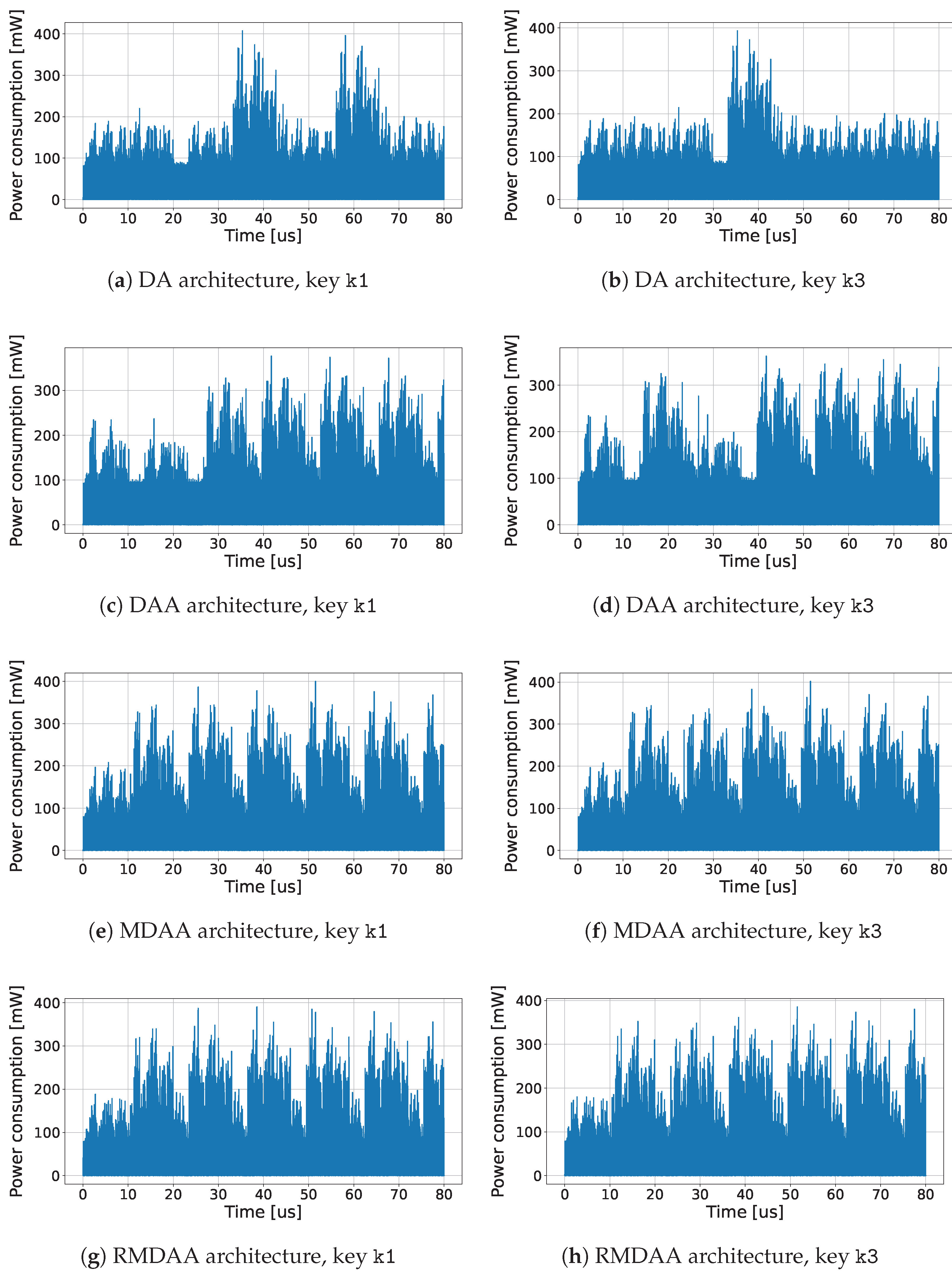
We used the simulated approach to assess the resistance to SPA attacks. Figure 14 shows some power traces for each accelerator configuration. In particular, the four pictures on the left side of Figure 14 are the ones acquired for the key k1, where the first one corresponds to the DA architecture, the second one for the DAA, the third one for the MDAA and the last one for the RMDAA. Instead, the four pictures on the right side of Figure 14 are the ones acquired for the key k3, where the first one corresponds to the DA architecture, the second one for the DAA, the third one for the MDAA and the last one for the RMDAA. As already stated in [14], the information leakage of DA architecture allows to easily retrieve the whole private key, instead of the DAA architecture where some part of the key can still be guessed. The power traces of the MDAA and RMDAA architectures are extremely similar and there are no substantial differences among them.
To further investigate the results of the architectures MDAA and RMDAA, we measured and plotted in Figure 15 the average power consumption during the computation of the PM operation. The power is averaged on the intervals corresponding to the use of an ECC key bit. While the MDAA architecture presents the same power consumption profile each time it is used with the same key, the RMDAA hides the information of the key, thanks to the randomness added by the random Z coordinate of the projective representation.
The result presented in this work related to the characterisation of the ECC Core must not be intended as complete and exhaustive, but the use-case aims to show how the proposed framework accelerates verification, validation and characterisation of SoC design workflows. In particular, the results obtained in previous work [14] required a few days of development and verification of the simulation and analysis environment itself. Here, the correct use of the various third-party tools, needed to complete the workflow, is ensured and automated by the proposed framework, which permitted the set up of the environment in around 30 min, plus 12 h of actual flow execution. Using the proposed framework, we can continue the SCA assessment of the ECC Core, in particular against the DPA attacks, which could require around thousands simulations and power analyses that will be completely automated. In an ordinary design flow, all the scripts for simulations and analyses must be carefully modified in order to adapt their use to the new necessities, with our framework instead, changing only few properties in the flow recipe permits to obtain very different design and verification environments.

5. Conclusions

This work described the use of a verification framework to automate the evaluation of software and hardware choices during co-design of SoC solutions. After the typical design workflow problems are introduced and the related works are compared, we described how our framework can be used to automate compilation of software applications, synthesis, cycle-true simulations, and power analyses. The aim of our solution is to make the framework capable of running a completely customized workflow, taking advantage of its versatility and modular structure to integrate various tools and assist even more complex use-cases. We illustrated the flow recipes, which provide a simple method for ensuring consistency among different workflow executions, improving cooperation in development teams by sharing configurations. Finally, we presented a use-case demonstrating how the framework can accelerate the setup of the verification environment used to assess the performance of the ECC accelerator embedded into the HSM module of the EPI chip. Area occupation, latency, power consumption, and resistance to SPA SCAs of four different accelerator configurations have been reported and discussed. The framework made it possible to significantly reduce the time taken to set up the various tools to perform the described use-case and collect the results.

Author Contributions

Conceptualization, L.Z., S.D.M. and P.N.; methodology, L.Z., S.D.M. and P.N.; software, L.Z.; validation, L.Z., S.D.M. and P.N.; investigation, L.Z., S.D.M. and P.N.; resources, S.D.M. and P.N.; data curation, L.Z., S.D.M. and P.N.; writing—original draft preparation, L.Z., S.D.M. and P.N.; writing—review and editing, L.Z., S.D.M., P.N., S.S. and L.F.; visualization, L.Z., S.D.M., P.N., S.S. and L.F.; supervision, S.S. and L.F.; project administration, S.S and L.F. All authors have read and agreed to the published version of the manuscript.

Funding

This research was funded by European Processor Initiative Specific Grant Agreement No 101036168.

Conflicts of Interest

The authors declare no conflict of interest.

Abbreviations

ABIApplication Binary Interface
AESAdvanced Encryption Standard
APIApplication Program Interface
ASICApplication Specific Integrated Circuit
AXIAdvanced eXtensible Interconnect
CPUCentral Processing Unit
DADouble-and-Add
DAADouble-and-Add-Always
DPADifferential Power Analysis
DRCDesign Rule Check
ECCElliptic Curve Cryptography
ECDHElliptic Curve Diffie-Hellman
ECDSA       Elliptic Curve Digital Signature Algorithm
ELFExecutable and Linkable Format
EPIEuropean Processor Initiative
FPGAField Programmable Gate Array
GUIGraphical User Interface
HAMMERHighly Agile Masks Made Effortlessly from RTL
HDLHardware Description Language
HSMHardware Secure Module
ISAInstruction Set Architecture
MDAAModified Double-and-Add-Always
MPSoCMulti-Processor Systems-on-Chip
P&RPlace-and-Route
PDKProcess Development Kit
PMPoint Multiplication
RAMRandom-Access Memory
RMDAARandomized Modified Double-and-Add-Always
ROMRead-Only Memory
RTLRegister Transfer Level
SCASide-Channel Attack
SDFStandard Delay Format
SDKSoftware-Development-Kit
SoCSystem-on-Chip
SPASimple Power Analysis
VCDValue Change Dump
VLSIVery Large Scale Integration

References

  1. Balkind, J.; Lim, K.; Schaffner, M.; Gao, F.; Chirkov, G.; Li, A.; Lavrov, A.; Nguyen, T.M.; Fu, Y.; Zaruba, F.; et al. BYOC: A “Bring Your Own Core” Framework for Heterogeneous-ISA Research. In Proceedings of the ASPLOS ’20—Twenty-Fifth International Conference on Architectural Support for Programming Languages and Operating Systems, Lausanne Switzerland, 16–20 March 2020; Association for Computing Machinery: New York, NY, USA, 2020; pp. 699–714. [Google Scholar] [CrossRef] [Green Version]
  2. Mittal, S.; Vetter, J.S. A Survey of CPU-GPU Heterogeneous Computing Techniques. ACM Comput. Surv. 2015, 47, 1–35. [Google Scholar] [CrossRef]
  3. Wolf, W.; Jerraya, A.A.; Martin, G. Multiprocessor System-on-Chip (MPSoC) Technology. IEEE Trans. Comput.-Aided Des. Integr. Circuits Syst. 2008, 27, 1701–1713. [Google Scholar] [CrossRef]
  4. Balkind, J.; McKeown, M.; Fu, Y.; Nguyen, T.; Zhou, Y.; Lavrov, A.; Shahrad, M.; Fuchs, A.; Payne, S.; Liang, X.; et al. OpenPiton: An Open Source Manycore Research Framework. SIGARCH Comput. Archit. News 2016, 44, 217–232. [Google Scholar] [CrossRef] [Green Version]
  5. Waterman, A.; Asanovic, K. (Eds.) The RISC-V Instruction Set Manual, Volume I: User-Level ISA, Document Version 20191213; RISC-V Foundation: San Francisco, CA, USA, 2019. [Google Scholar]
  6. Nannipieri, P.; Di Matteo, S.; Zulberti, L.; Albicocchi, F.; Saponara, S.; Fanucci, L. A RISC-V Post Quantum Cryptography Instruction Set Extension for Number Theoretic Transform to Speed-Up CRYSTALS Algorithms. IEEE Access 2021, 9, 150798–150808. [Google Scholar] [CrossRef]
  7. Chen, W.; Ray, S.; Bhadra, J.; Abadir, M.; Wang, L. Challenges and Trends in Modern SoC Design Verification. IEEE Des. Test 2017, 34, 7–22. [Google Scholar] [CrossRef]
  8. Zulberti, L.; Nannipieri, P.; Fanucci, L. A Script-Based Cycle-True Verification Framework to Speed-Up Hardware and Software Co-Design of System-on-Chip exploiting RISC-V Architecture. In Proceedings of the 2021 16th International Conference on Design Technology of Integrated Systems in Nanoscale Era (DTIS), Montpellier, France, 28–30 June 2021; pp. 1–6. [Google Scholar] [CrossRef]
  9. Bash. by Free Software Foundation. Available online: https://www.gnu.org/software/bash (accessed on 11 November 2022).
  10. Spike RISC-V ISA Simulator. Available online: https://github.com/riscv-software-src/riscv-isa-sim (accessed on 11 November 2022).
  11. Sarti, L.; Baldanzi, L.; Crocetti, L.; Carnevale, B.; Fanucci, L. A Simulated Approach to Evaluate Side Channel Attack Countermeasures for the Advanced Encryption Standard. In Proceedings of the 2018 14th Conference on Ph.D. Research in Microelectronics and Electronics (PRIME), Prague, Czech Republic, 2–5 July 2018; pp. 77–80. [Google Scholar] [CrossRef]
  12. Adegbija, T.; Rogacs, A.; Patel, C.; Gordon-Ross, A. Microprocessor Optimizations for the Internet of Things: A Survey. IEEE Trans. Comput.-Aided Des. Integr. Circuits Syst. 2018, 37, 7–20. [Google Scholar] [CrossRef] [Green Version]
  13. Nannipieri, P.; Matteo, S.D.; Baldanzi, L.; Crocetti, L.; Zulberti, L.; Saponara, S.; Fanucci, L. VLSI Design of Advanced-Features AES Cryptoprocessor in the Framework of the European Processor Initiative. IEEE Trans. Very Large Scale Integr. (VLSI) Syst. 2022, 30, 177–186. [Google Scholar] [CrossRef]
  14. Di Matteo, S.; Baldanzi, L.; Crocetti, L.; Nannipieri, P.; Fanucci, L.; Saponara, S. Secure Elliptic Curve Crypto-Processor for Real-Time IoT Applications. Energies 2021, 14, 4676. [Google Scholar] [CrossRef]
  15. Hoffmann, A.; Kogel, T.; Nohl, A.; Braun, G.; Schliebusch, O.; Wahlen, O.; Wieferink, A.; Meyr, H. A novel methodology for the design of application-specific instruction-set processors (ASIPs) using a machine description language. IEEE Trans. Comput.-Aided Des. Integr. Circuits Syst. 2001, 20, 1338–1354. [Google Scholar] [CrossRef]
  16. Kinsy, M.A.; Pellauer, M.; Devadas, S. Heracles: A Tool for Fast RTL-Based Design Space Exploration of Multicore Processors. In Proceedings of the FPGA ’13—ACM/SIGDA International Symposium on Field Programmable Gate Arrays, Monterey, CA, USA, 11–13 February 2013; Association for Computing Machinery: New York, NY, USA, 2013; pp. 125–134. [Google Scholar] [CrossRef] [Green Version]
  17. Genko, N.; Atienza, D.; De Micheli, G.; Benini, L. Feature-NoC emulation: A tool and design flow for MPSoC. IEEE Circuits Syst. Mag. 2007, 7, 42–51. [Google Scholar] [CrossRef] [Green Version]
  18. de Micheli, G.; Benini, L. Networks on Chip: A New Paradigm for Systems on Chip Design. In Proceedings of the DATE ’02—Conference on Design, Automation and Test in Europe, Paris, France, 4–8 March 2002; IEEE Computer Society: Washington, DC, USA, 2002; p. 418. [Google Scholar]
  19. Pani, D.; Palumbo, F.; Raffo, L. A fast MPI-based parallel framework for cycle-accurate HDL multi-parametric simulations. Int. J. High Perform. Syst. Archit. 2010, 2, 187–202. [Google Scholar] [CrossRef]
  20. Wang, S.; Possignolo, R.T.; Skinner, H.B.; Renau, J. LiveHD: A Productive Live Hardware Development Flow. IEEE Micro 2020, 40, 67–75. [Google Scholar] [CrossRef]
  21. Tagliavini, G.; Rossi, D.; Marongiu, A.; Benini, L. Synergistic HW/SW Approximation Techniques for Ultralow-Power Parallel Computing. IEEE Trans. Comput.-Aided Des. Integr. Circuits Syst. 2018, 37, 982–995. [Google Scholar] [CrossRef] [Green Version]
  22. HAMMER: Highly Agile Masks Made Effortlessly from RTL. By UC Berkeley Architecture Research. Available online: https://github.com/ucb-bar/hammer (accessed on 11 November 2022).
  23. Chipyard Framework. By UC Berkley Architecture Research. Available online: https://github.com/ucb-bar/chipyard (accessed on 11 November 2022).
  24. European Processor Initiative. Available online: https://www.european-processor-initiative.eu (accessed on 11 November 2022).
  25. seL4 Microkernel. A Series of LF Projects, LLC. Available online: https://sel4.systems (accessed on 11 November 2022).
  26. Zephyr Project. A Linux Foundation Project. Available online: https://www.zephyrproject.org (accessed on 1 November 2022).
  27. Yocto Project. A Linux Foundation Collaborative Project. Available online: https://www.yoctoproject.org (accessed on 11 November 2022).
  28. Newlib C standard Library. Maintained by Red Hat. Available online: https://sourceware.org/newlib (accessed on 11 November 2022).
  29. Zaruba, F.; Benini, L. The Cost of Application-Class Processing: Energy and Performance Analysis of a Linux-Ready 1.7-GHz 64-Bit RISC-V Core in 22-nm FDSOI Technology. IEEE Trans. Very Large Scale Integr. (VLSI) Syst. 2019, 27, 2629–2640. [Google Scholar] [CrossRef]
  30. NIST, F. FIPS 186-4–Digital Signature Standard (DSS). 2013. Available online: https://csrc.nist.gov/publications/detail/fips/186/4/final (accessed on 11 November 2022).
  31. Möller, B. Parallelizable elliptic curve point multiplication method with resistance against side-channel attacks. In Information Security, Proceedings of the International Conference on Information Security, Sao Paulo, Brazil, 30 September–2 October 2002; Springer: Berlin/Heidelberg, Germany, 2002; pp. 402–413. [Google Scholar]
  32. Giraud, C.; Verneuil, V. Atomicity improvement for elliptic curve scalar multiplication. In Smart Card Research and Advanced Application, Proceedings of the International Conference on Smart Card Research and Advanced Applications, Passau, Germany, 14–16 April 2010; Springer: Berlin/Heidelberg, Germany, 2010; pp. 80–101. [Google Scholar]
  33. Dupuy, W.; Kunz-Jacques, S. Resistance of randomized projective coordinates against power analysis. In Cryptographic Hardware and Embedded Systems—CHES 2005, Proceedings of the International Workshop on Cryptographic Hardware and Embedded Systems, Edinburgh, UK, 29 August–1 September 2005; Springer: Berlin/Heidelberg, Germany, 2005; pp. 1–14. [Google Scholar]
Figure 1. Common Workflow for Heterogeneous Digital Systems Design.
Electronics 11 03704 g001
Figure 2. Structure of the Framework. From the left, the Baremetal SDK used to compile software; the RTL Library containing all the HDL sources; the tool handlers which manage actual tools and inter-tool dependencies; the projects which are used to configure the workflow. Below there are the four third-party tools we have integrated into the framework.
Electronics 11 03704 g002
Figure 3. A Directory Tree of an Example Project.
Electronics 11 03704 g003
Figure 4. Typical Design Workflow.
Electronics 11 03704 g004
Figure 5. Flow execution and customization of the software compilation phase.
Electronics 11 03704 g005
Figure 6. Structure of the Baremetal SDK.
Electronics 11 03704 g006
Figure 7. Flow execution, dependencies, and customization of the synthesis phase.
Electronics 11 03704 g007
Figure 8. Flow execution, dependencies, and customization of the simulation phase.
Electronics 11 03704 g008
Figure 9. Flow execution, dependencies, and customization of the power analysis phase.
Electronics 11 03704 g009
Figure 10. Description of the VCD limited type of workflow when the limiting factor is set to 5 and there are two synthesised modules per simulation to analyse.
Electronics 11 03704 g010
Figure 11. Structure of a general SoC.
Electronics 11 03704 g011
Figure 12. The System-On-Chip for the Evaluation of the ECC module.
Electronics 11 03704 g012
Figure 13. Architecture of the ECC Core described in [14].
Electronics 11 03704 g013
Figure 14. Power trace for k1 (the least significant part is K = ..101010, with MSB first) of DA (a), DAA (c), MDAA (e), RMDAA (g) and for k3 (the least significant part is K = ..010101, with MSB first) of DA (b), DAA (d), MDAA (f), RMDAA (h).
Electronics 11 03704 g014
Figure 15. Power trace for k1 (the least significant part is K = ..101010, with MSB first) of MDAA (a), RMDAA (c,e,g), and for k3 (the least significant part is K = ..010101, with MSB first) of MDAA (b), RMDAA (d,f,h).
Electronics 11 03704 g015
Table 1. Performance results for the four ECC Core configurations averaged on the different execution with the six keys. Power and latency of the DA architecture strongly depends on the Hamming weight of the key that is around 128.
ECC PM
Config
Area
(kGE)
Latency
(us)
Power
(mW)
Peak
(mW)
DA247.9232.25657.1407.1
DAA253.8836.88069.7394.0
MDAA248.0536.84868.1401.3
RMDAA249.8036.84868.6398.5
Publisher’s Note: MDPI stays neutral with regard to jurisdictional claims in published maps and institutional affiliations.