Article

FLIA: Architecture of Collaborated Mobile GPU and FPGA Heterogeneous Computing

School of Computer Science, University of Science and Technology of China, Hefei 230052, China
*
Author to whom correspondence should be addressed.
Electronics 2022, 11(22), 3756; https://doi.org/10.3390/electronics11223756
Submission received: 10 October 2022 / Revised: 4 November 2022 / Accepted: 14 November 2022 / Published: 16 November 2022
(This article belongs to the Section Computer Science & Engineering)

Abstract

:
Accelerators, such as GPUs (Graphics Processing Unit) that is suitable for handling highly parallel data, and FPGA (Field Programmable Gate Array) with algorithms customized architectures, are widely adopted. The motivation is that algorithms with various parallel characteristics can efficiently map to the heterogeneous computing architecture by collaborated GPU and FPGA. However, current applications always utilize only one type of accelerator because the traditional development approaches need more support for heterogeneous processor collaboration. Therefore, a comprehensible architecture facilitates developers to employ heterogeneous computing applications. This paper proposes FLIA (Flow-Lead-In Architecture) for abstracting heterogeneous computing. FLIA implementation based on OpenCL extension supports task partition, communication, and synchronization. An embedded system of a three-dimensional waveform oscilloscope is selected as a case study. The experimental results show that the embedded heterogeneous computing achieves 21× speedup than the OpenCV baseline. Heterogeneous computing also consumes fewer FPGA resources than the pure FPGA accelerator, but their performance and energy consumption are approximate.

1. Introduction

In many applications nowadays, embedded SoCs (System-on-a-Chip) integrate mobile GPU (Graphics Processing Unit) that optimizes image rendering. As an accelerator of the host CPU (Central Processing Unit), FPGA (Field Programmable Gate Array) accelerates the algorithm and reduces energy consumption at the hardware level.
The motivation is that mobile GPU supports accelerating general algorithms by OpenCL development [1]. Therefore, the algorithms with diverse parallel characteristics can pertinently map to the heterogeneous GPU-FPGA accelerators. The heterogeneous computing platform successfully combines flexibility and efficiency [2]. Meanwhile, image processing tasks offloaded from the FPGA into GPU will reduce the usage of FPGA resources.
However, in the common scenario, the applications always utilize only one type of accelerator. The traditional development toolchain lacks portability and collaboration of heterogeneous accelerators. The collaborative GPU-FPGA design faces a series of challenges: (1) The development environment and the programming toolchain of these accelerators are reasonably different. A unified and comprehensive development model will facilitate the application of heterogeneous computing. (2) The programming languages should be portable to various accelerators while ensuring individual performance. Specific architectural optimizations are necessary to explore the performance potential of the accelerator. (3) Heterogeneous computing involves tasks partitioning, mapping, and other jobs, that lead to vast combinations of design space.
To solve the above problems, this paper proposes FLIA (Flow-Lead-In Architecture) to abstract heterogeneous computing that supports task partitioning, communication, and synchronization. This paper also extends OpenCL and presents two communication mechanisms.
This paper contributes in the following aspects:
  • The comprehensible FLIA and its implementation facilitate developers to employ heterogeneous computing applications.
  • A case study developed on the collaborated mobile GPU and FPGA platform proves the effectiveness of heterogeneous computing.
The paper is organized as follows: Section 2 overviews the background and related work. Section 3 presents the Flow-Lead-In architecture, including the model description and model analysis, then Section 4 describes the implementation of the FLIA architecture. Section 5 proposes the case study design, and Section 6 shows the evaluation results. Finally, Section 7 concludes the paper.

2. Background and Related Work

Many applications benefit from heterogeneous computing, e.g., the virtual reality field uses the global illumination algorithm on mobile SoC with CPU and GPU [3], whose approach increases CPU utilization from 13% to 80%. In the collaborated CPU and mobile GPU computing, [4] reduces the data initialization latency caused by the shared memory of heterogeneous processors. [5] profits from CPU-FPGA collaboration in the cloud-accelerating environment.

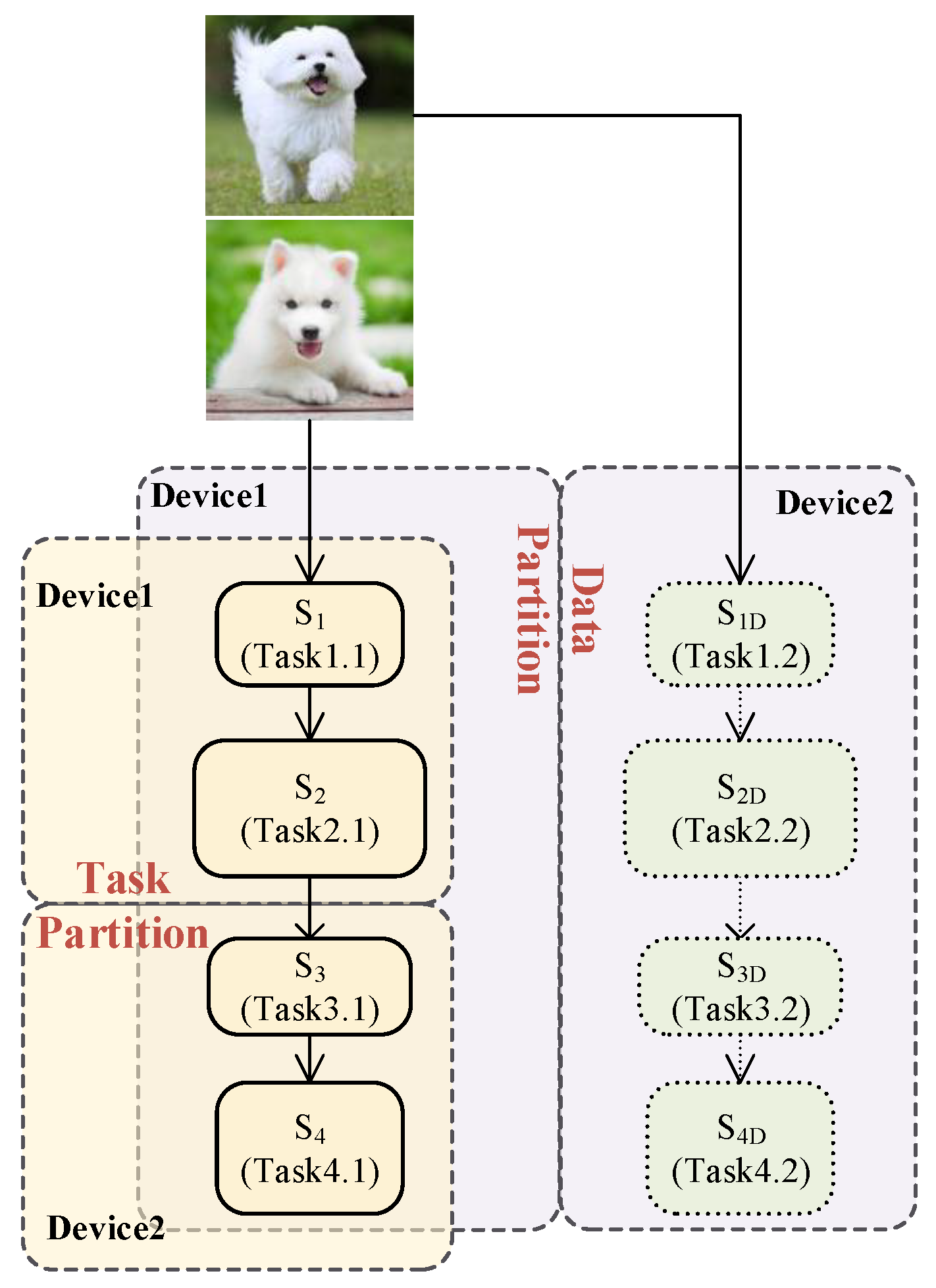
2.1. Heterogeneous Computing Workload Partioning

The current mainstream idea of heterogeneous computing is to partition the overall computing task into small workloads. [6] classifies the partitioning methods into two categories, task partitioning and data partitioning.
CED (Canny Edge Detection) is an edge detection algorithm that consists of four stages: (1) a Gaussian filter, (2) a Sobel filter, (3) non-maximum suppression, and (4) hysteresis. As shown in Figure 1, lateral data partitioning means the heterogeneous accelerators perform the identical task with different subsets of the data. Vertical task partitioning means each heterogeneous accelerator performs various sub-tasks and communicates between devices. Taking CED processing a stream of video frames as an example, in the case of data partitioning, each heterogeneous accelerator handles a mutually disjoint set of frames. As task partitioning, all frames are serially processed by the first two stages on device1, then by the last two stages on device2.
Each partitioning strategy entails its tradeoffs. The main challenge with data partitioning is determining the distribution of data workloads across devices that results in the workload balance. MultiFastFit [7] divides consecutive iterations into chunks, whose sizes are modeled to ensure performance and resource utilization. Similarly, HGuided [8] dynamically calculates partitioned data packets size with considering the power of various accelerators. In order to reduce the idle time of each accelerator, the data partitioning method tends to divide data workloads into smaller sizes, which increases the cost of sub-task synchronization.
On the other side, task partitioning does not need to deploy FPGA resources to all sub-tasks, because part of sub-tasks entirely runs on the GPU or CPU. Refs. [9,10] propose task-level schedulers to accelerate the modules running in parallel on FPGA. HRES is a task partitioning method based on DPR (dynamic partial reconfiguration) [11]. HRES implements an identical task with different scaling factors to facilitate the scheduling algorithm fills up the resource slots on FPGA [12].
As a result, task partitioning generally enables more task duplication on the FPGA than data partitioning, and gains better overall performance in most application scenarios [13]. FLIA adopts a task partitioning strategy that is suitable for the application scenario of the data processing pipeline. CAL provides a data flow programming language whose primary concern is converting the model to hardware description language [14]. CDFG adopts directed acyclic graph as an input format to high-level synthesis tools, which is always used to study the CPU and FPGA tasks partition [15], and positively inspires FLIA. However, FLIA focus on the heterogeneous accelerators collaboration and the communication mechanism between tasks.

2.2. OpenCL Runtime

OpenCL is a platform-independent open standard that supports compiling CPUs, GPUs, and FPGAs from various accelerator vendors [16]. Base64 encoding [17], Face recognition [18], object removal [19], and SIFT (scale-invariant feature transform) feature detector [20] are developed using OpenCL on mobile GPUs. K-Nearest neighbor and bitonic sorting algorithms have been modeled in OpenCL for both GPU and FPGA [21]. However, OpenCL does not focus on the hardware and software tasks partitioning, nor the communication between modules on heterogeneous accelerators [22].
Previous [7,12,13] perform data partitioning studies based on OpenCL. These experiments only accelerate one algorithm at a time, because OpenCL cannot natively support task-level scheduling in heterogeneous computing.
Although OpenCL is portable at the language level, the toolchains provided by accelerator vendors are hard to work together, especially for collaborated heterogeneous accelerators. Ref. [23] extracts kernel-level task parallelism from in-order queues by extending an open-source implementation of OpenCL. In addition, OpenCL natively lacks several critical mechanisms of heterogeneous computing, such as communication and synchronization across accelerators, which are manually implemented by many studies. Ref. [7] provides HBB library to fill the gap of OpenCL for heterogeneous computing. Therefore, this paper proposes FLIA that extends the OpenCL to simplify of heterogeneous computing applications.

3. Flow-Lead-In Architecture for Heterogeneous Computing

Heterogeneous computing faces problems with development complexity and high barriers to entry. FLIA abstracts an application as a data-flow-driven processing pipeline consisting of servants and execution-flows. Quoting the concepts from OS area of SEFM (Servant & Execution-Flow Model) [24,25], the servant stands for the functional module that accomplishes specific computational task in the system. The execution-flow represents the data-flow between the servants, and is responsible for communication and synchronization. The FLIA owns four characteristics: portability, encapsulation, parallelism, and reusability:
  • Portability: As an abstraction of the computational unit, the servant does not dedicate to the specific accelerator.
  • Encapsulation: The servant is a self-fulfilled module. The developers only focus on the algorithm of the servant, knowing neither the details of FLIA runtime nor the internal implementation of other servants.
  • Parallelism: Multiple servants can run on heterogeneous accelerators in parallel to improve system performance.
  • Reusability: The design of the servant can be reused on various accelerators.

3.1. Model Definition

The application is modeled as a sextuple:
M ( S , Q , C , δ , Q 0 , F )
S is the servant, Q is the execution-flow, C is the computational resource, δ is the state transition function, Q 0 and F are the initial and terminated states. The definitions in more detail are as follows:
Definition: Servant S: An operational component that can perform a particular computing task.
The system has a set of N servants represented as:
S = { S i | i N }
This model specifies that a servant is a minimum unit that can be loaded and unloaded while the system runs. Thus, the servant is the fundamental unit of scheduling in heterogeneous computing.
Definition: Execution-flow Q: Message (data structure) transferred between servants. Execution-flow is represented as symbol ×, and indicated by an arrow in diagrams. As shown in Figure 2, the computing result of the servant S1 transfers to S2 for the subsequent processing. This execution-flow is represented as:
S 1 × S 2
The set of execution-flows in the system is:
Q = { Q i j | i , j N         Q i j       Q i j M i j }
Q i j stands for the execution-flow S i × S j . Both i and j range from 1 to N (N is the total number of servants). Q i j indicates the number of messages on the execution-flow that S i has produced but S j has not consumed. When the leading servant S i completes and generates its output, an additional message exists on the execution-flow, i.e., Q i j = 1 . After the subsequent servant S j consumes this message, Q i j = 0 .
An execution-flow has dual roles: (1) Data communication. The execution-flow describes the communication relationship between the servants. (2) Drive the successive servants to start execution. After a servant executes completed, the generated execution-flow will issue the successor servant to push the whole computing task. Therefore, the FLIA is driven by data flow, which is different from the Von Neumann architecture of instruction-driven.
Definition: FIFO-execution-flow: The execution-flow contains FIFO (First-In-First-Out) queue. The FIFO can buffer one or more messages. M i j is defined as the maximum legal capacity of FIFO Q i j . Therefore, Q i j = M i j means buffers of FIFO are full.
Definition: Resource C: The set of processing units is:
C s e t = { G P U , F P G A , C P U }
States of the resources can be:
C s t a t e = { B U S Y , I D L E }
Then, the set of resources is:
C = { C i R i | i N C i C s t a t e R i C s e t }
Definition: State transition function δ :
δ ( C i = I D L E , j ( Q i j < M i j ) k Q k i 0 ) Δ C i = B U S Y δ ( C i = B U S Y , C i = I D L E ) Δ ( Q k i Q , Q k i ) ( Q i j Q , Q i j + + )
As shown in Figure 3, the first state transition function means the servant S i will occupy resource and issue execution while S i meets the following three conditions simultaneously: (1) S i is under resource idle state; (2) j ( Q i j < M i j ) , i.e., any output port has free space; (3) k Q k i 0 , i.e., all input ports are not empty.
The second state transition function means that when the resource’s state of servant S i changes from BUSY to IDLE, the space count of each input buffer decreases and the space count of output buffer increases.

3.2. Model Analysis

FLIA is analyzed using the directed graph of graph theory, which defines:
  • Vertex: The servant is regarded as the vertex of the graph.
  • Edge: The execution-flow is regarded as the edge of the graph.
  • Weight of edge: The sum of a servant’s execution duration and its initiated execution-flow’s communication duration.
  • Path: A path between servants S A and S B means that the execution result of S A is processed by one or many servants finally sent to S B . Such as Figure 4, there are two paths between the servants S A and S B .
To simplify following analysis, the weights of all edges are assumed to be 1, i.e., the execution duration of all servants is identical. For a graph with multiple paths, like Figure 4, the result from starting point transfers through all paths and eventually arrive at S B . Considering the spanning tree with S B as the root vertex, weighted depths of S A are 2 and 3, respectively. Different depths mean that the operands issued by S A along two paths do not arrive at S B simultaneously.
Analysis 1 Synchronous flow controlling: If there are multiple paths between head-end and tail-end servants, even if each path has different execution duration, the tail-end servant’s inputs always consume the same operand from the head-end servant.
Taking Figure 4 as an example, operands arrived at S A are marked by α, β, γ… in chronological order. Table 1 shows the execution space-time diagram of Figure 4.
At the moment t1, operand α is transferred from S A to S X and S Y simultaneously while a new operand β arrives at S A .
At the moment t2, α from S X arrives S B , while α from S Y arrives S Z without reaching S B . According to the state transition conditions, S B does not meet the third condition (execution-flows of all input ports are ready). Thus, S B does not run, causing that S X not to meet the second condition (execution-flows of all output ports transfer to the successive servant). Consequently, S A does not run.
At the moment t3, α goes through both paths and arrives at S B . S X processes β then S A processes γ .
The following process is similar to those mentioned above.
According to the initial analysis of Table 1, the servant S B in the tail never fetches different operands from two paths simultaneously. Therefore, it can be conjectured that if there are multiple paths between two servants, the operands of the tail-end servant are always from the same operand transferred by the head-end servant. This phenomenon is called synchronous flow controlling.
The inductive proof: The pipeline is empty at the start-up. Then the first operand α issues and arrives S B along the less weighted path in advance of the path with heavy weight. However, S B does not meet the third state transition condition that ‘all inputs are ready’. Therefore, S B will not run until the operands from all children vertices arrive. (1) For the first operand, the above conjecture is true. (2) Assuming the conjecture is also true for the operand n. Then the computing resource of S B is occupied by operand n. Two servants before S B can execute the operand (n + 1), according to the second state transition condition. (3) S B runs when two operands (n + 1) both arrive from the previous servants, according to the third state transition condition. So, the conjecture for the two paths is true.
If there is only one path between two servants, i.e., a simple serial flow without any branch, such as Figure 2, the above conjecture is true. Using the inductive method again, it is easily obtained that the conjecture remains true when there are multiple paths between two servants.
Due to the intrinsic feature of synchronous flow controlling, there is no write-conflict problem caused by the multiple-issuing of the Von Neumann processor. Thus, the FLIA is beneficial to developing a parallel computing system.
Analysis 2 The elimination of different execution duration of paths: The execution duration analysis of the intersected paths benefits from a spanning tree, which is derived from the intersected vertex as the root. The weighted depth of the spanning tree’s leaf vertex equals its path’s total running duration. Therefore, the total running duration of the whole spanning tree depends on the path with the deepest leaf. According to Amdahl’s law, optimization efforts aim at the path with the largest weight.
Analysis 3 Cyclic execution-flows and deadlock: Figure 5 is an example of execution-flows with a loop, where S B and S D are two vertices on the loop. In the initialization, since S B is the successor of S D , S B must wait for the output of S D to start. At the same time, S D must wait for S B . Both S B and S D are waiting for the resource held by each other, which originates a classic deadlock problem.
Being similar with the process of solving the deadlock in the operating system field, one of the cyclic servants should first acquire all necessary resources. For instance, an initial execution-flow should be output by S D when the system boots. By this time, S B starts after the execution-flow arrival from S A . Then the S B output execution-flow starts S D . This loop will continue till the entire operation completed.

4. Implementation of FLIA

FLIA is suitable for the data processing pipeline application that always contains multiple stages, and each stage can run on an accelerator. Thus, numerous stages can run in parallel on heterogeneous accelerators. FLIA implements this feature based on an extension of OpenCL, whose architecture is shown in Figure 6. FLIA involves variety of heterogeneous accelerators, each with a vendor-dedicated OpenCL runtime. The scheduler of FLIA integrates these runtimes for collaborative work.

4.1. Servant Implementation

A servant consists of two critical elements: kernel function and parametric-instantiation. In practice, the kernel function is usually the innermost iteration of large nested loops [23]. Vendor-specific OpenCL toolchain compiles the source code of the kernel then the kernel maps to various accelerators. The scheduler inserts the kernel into the commands queue of the corresponding accelerator runtime and issues the kernel execution. The optimization of the generated logic circuit and executable code inner a servant is not done by FLIA, but a task of the OpenCL compiler.

4.2. Execution-Flow Implementation

Typically, there are communication and coordination overheads involved in heterogeneous computing. The execution-flow is responsible for this critical work. The scheduler of FLIA listens to the events from all accelerator vendor-specific runtimes. When the vendor-specific OpenCL runtime calls clFinish() hook function to indicate the completed signal of a servant, the scheduler performs the state transition functions, including transactions as buffer copy, multiple servants execution synchronizations, new servant issuing, etc.
A hardware implementation of execution-flow, referring to the bus-style communication architecture of OneSys [26], is presented in Figure 7. All FPGA-based servants and a memory controller with MMU (Memory Management Unit) are attached to the bus.
FLIA maps the data inner an execution-flow to an area of memory. S A × S B is taken as an example for illustration: The servant S A writes computing results to the memory as an output execution-flow. After that, the FLIA scheduler switches this memory area to the address space of the subsequent servant S B using MMU. After that, the data packet is transferred from S A to S B . This design reduces memory duplication between FPGA servants.
In the case of bus-style communication, the execution-flow is sent to the subsequent servant S B , then S B starts executing. At this time, if S A produces a new execution-flow that requires a memory writing operation, the bus will conflict with S B reading operation. It is necessary to extend the bus-style execution-flow.
The architecture of the post-style execution-flow is shown in Figure 8. It contains multiple buses, and all servants share each bus. When the writing operation of S A conflicts with the reading operation of S B , the FLIA scheduler will choose a new bus for S A to reduce the latency of bus waiting.

5. Case Studies

The 3D waveform oscilloscope displays the time-amplitude information of the signal. Furthermore, it can use the pseudo-color and luminance to present the waveform’s statistical information. Through this method, the 3D waveform takes advantage of capturing incidental events such as burrs [27]. The application’s block diagram is shown in Figure 9.
3D waveforms oscilloscope is built by four commonly used algorithms, string matching, matrix addition, histogram, and contrast stretching. Among these algorithms, string matching and matrix addition belong to the field of digital processing, and histogram and contrast stretching belong to the field of image processing.
Servant1 String Matching: This stage servant matches the trigger pattern in the input sample stream and aligns each waveform segment onto that trigger point to stabilize the afterglow display. The sample stream is treated as a string, which is processed by the Brute Force string matching algorithm. The matched waveform segment is a two-dimensional plot with time as the horizontal axis.
Servant2 Matrix Accumulator: This stage servant stacks a series of 2D waveform segment plots from the previous stage onto a 3D surface map by the matrix addition algorithm.
Servant3 Histogram: This stage servant converts the 3D surface map into a pseudo-color image through the histogram algorithm.
Servant4 Contrast stretching: This stage servant transforms the pseudo-color image into a thermal map using the contrast stretching algorithm, which enhances the dark brightness of low-probability events.

6. Results

6.1. Experimental Setup

The experiments are conducted on an embedded system with FPGA and mobile SoC collaboration. The SoC is Freescale i.MX6Q includes quad-core ARM Cortex-A9 CPU and Vivante GC2000 GPU, with 2-channels 32-bits memory bandwidth. This ARM processor supports the NEON vector instruction set, essentially an implementation of SIMD (Single Instruction/Multiple Data), which supports four 32-bit integers, four single-precision floating-point, and eight 8-bit integers operations within a single instruction [28]. The Xilinx Kintex-7 series FPGA contains four independent 16-bit memory banks. The FPGA board connects to the SoC via a 1-lane PCI-e 2.0 interface.
Four commonly used algorithms, S1 string matching, S2 matrix addition, S3 histogram, and S4 contrast stretching, are selected as benchmarks. OpenCV library with OpenMP support [29] is the experimental baseline.

6.2. Servants Acceleration

The servants are developed on GPU and FPGA using OpenCL language [30]. FPGA adopts the declarative optimization methods provided by OpenCL. These optimization methods include: UL (Loop Unrolling) and SIMD. UL method unrolls inner loop to increase concurrent execution paths and reduce iterations. ULw represents w loops are transformed into parallel computational units, i.e., w units run on FPGA simultaneously. OpenCL also supports combining v scalar arithmetic operations into a vector operation to be SIMDv.
The measurement results of the throughput of each servant are shown in Figure 10. The mobile GPU achieves 1.9–3.8× speedup over the baseline (traditional CPU). FPGA can change the hardware architecture to meet the characteristics of the algorithms, which is different from GPU. The pipeline in FPGA owns extremely high parallelism of the arithmetic units. For example, the suffix of SIMD in Figure 10, ‘8’ represents that the computing unit on the FPGA processes 8 data simultaneously. By duplicating more computing units, FPGA obtains greater acceleration, while more resources are costed as an expense. Minimum parallelism optimized FPGA achieves 2.7–10.5× speedup over the baseline.

6.3. Heterogeneous Computing Evaluation

FLIA is suitable for the application scenario of the data processing pipeline. According to Amdahl’s Law: The overall performance of a data processing pipeline is determined by the bottleneck stage with the lowest throughput. Because FLIA improves the entire performance through the pipelined parallel, the execution duration of each stage should be as balanced as possible [31]. The throughput advantage of just one stage is not confident of enhancing overall performance.
In this case study 3D waveform oscilloscope, the ADC can sample up to 1G points in a second, and the image processing servants should handle 60 frames per second. Therefore, considering the coordination of modules in this application, the execution frequency of each servant is different. To accomplish these tasks, the execution duration required for each servant is normalized, as Figure 11 shows. For image processing servants (histogram and grayscale stretching), their performance on GPU approximates that on FPGA with SIMD8 optimization. This experiment uses a fixed-point calculation to utilize the DSP arithmetic unit in FPGA [32].
The following experiment is that all servants use only one type of processing resource, CPU, GPU, or FPGA. As Figure 12, FPGA can achieve 22× speedup, but the higher speedup is at the cost of higher parallelism and more resource usage. Then, as a comparison, FPGA and GPU collaborate to implement the same application. There is always an ample design exploration space for the FPGA and GPU collaborating acceleration. For example, these four servants are mapped to FPGA and GPU with combinations of C 4 1 + C 4 2 + C 4 3 = 14 . Automatic scheduling based on the throughput of servants should be future work. To keep the pipeline stages balanced, according to the single servant required execution duration in Figure 11, the data processing algorithms (S1 string matching, S2 matrix addition) run on FPGA, and the image processing algorithms (S3 histogram, S4 grayscale stretching) run on GPU. It is also reasonable to place adjacent servants in the same accelerator, which can reduce memory duplication. The overhead of copying memory data between heterogeneous accelerators is still significant. An efficient communication mechanism should be future work.
In Figure 12, comparing execution-flow communication implementation, the post-style achieves an average 1.3× speedup over the bus-style. Taking the 16 computing units parallelism on FPGA as an example, collaborated GPU-FPGA achieves 21× and 10.5× performance than the CPU baseline and mobile GPU. The heterogeneous computing approaches the performance of the pure FPGA accelerator, while it only consumes about 15% DSP resource of the pure FPGA accelerator.

6.4. Power Evaluation

In Figure 13, the power increases in the order of CPU, GPU, then FPGA, and the energy consumption is in the reverse turn. The energy consumption of the CPU is about 5 times that of FPGA. The energy efficiency of collaborated GPU-FPGA is slightly lower (<10%) than the pure FPGA.

7. Conclusions

This paper proposes FLIA for the collaboration of mobile GPU and FPGA to accelerate the data processing pipeline. Evaluations are conducted on the case study embedded system, 3D waveform oscilloscope. From the experimental results, the benchmark algorithms are accelerated by 1.9–3.8× and 2.7–10.5× on GPU and FPGA respectively, over the OpenCV baseline. The post-style execution-flow achieves an average 1.3× better performance than bus-style. The embedded heterogeneous computing achieves 21× speedup than the OpenCV baseline. Moreover, the collaborate GPU-FPGA consumes fewer FPGA resources than pure FPGA accelerators, but their performance and energy consumption are approximate.
In the future, the work will focus on the following aspects: (1) Iteratively improve FLIA by researching more practical applications. (2) FLIA should support more accelerators, such as multi-core CPUs. (3) Automatic scheduling. The heterogeneous mapping schemes of servants influence the performance enormously. Exploring huge design spaces ought to be more efficient.

Author Contributions

Writing—original draft preparation, N.H.; writing—review and editing, C.W. and X.Z. All authors have read and agreed to the published version of the manuscript.

Funding

This work was supported in part by the National Key R&D Program of China under Grants 2017YFA0700900 and 2017YFA0700903, in part by the National Natural Science Foundation of China under Grants 62102383, 61976200, and 62172380.

Conflicts of Interest

The authors declare no conflict of interest.

References

  1. Ross, J.A.; Richie, D.A.; Song, J.P.; Shires, D.R.; Pollock, L.L. A case study of OpenCL on an Android mobile GPU. In Proceedings of the High PERFORMANCE Extreme Computing Conference, Waltham, MA, USA, 9–11 September 2014; pp. 1–6. [Google Scholar]
  2. Seewald, A.; Schultz, U.P.; Ebeid, E.; Midtiby, H.S. Coarse-Grained Computation-Oriented Energy Modeling for Heterogeneous Parallel Embedded Systems. Int. J. Parallel Program. 2021, 49, 136–157. [Google Scholar] [CrossRef]
  3. Kim, S.K.; Man, K.S. Efficient Path Tracer for the Presence of Mobile Virtual Reality. Hum.-Cent. Comput. Inf. Sci. 2021, 11, 1–14. [Google Scholar]
  4. Wang, Z.; Jiang, Z.; Wang, Z.; Tang, X.; Liu, C.; Yin, S.; Hu, Y. Enabling Latency-Aware Data Initialization for Integrated CPU/GPU Heterogeneous Platform. IEEE Trans. Comput.-Aided Des. Integr. Circuits Syst. 2020, 39, 3433–3444. [Google Scholar] [CrossRef]
  5. Jordan, M.G.; Korol, G.; Rutzig, M.B.; Beck, A.C.S. Resource-Aware Collaborative Allocation for CPU-FPGA Cloud Environments. IEEE Trans. Circuits Syst. II Express Briefs 2021, 68, 1655–1659. [Google Scholar] [CrossRef]
  6. Belviranli, M.E.; Bhuyan, L.N.; Gupta, R. A dynamic self-scheduling scheme for heterogeneous multiprocessor architectures. ACM Trans. Arch. Code Optim. 2013, 9, 1–20. [Google Scholar] [CrossRef] [Green Version]
  7. Rodríguez, A.; Navarro, A.; Nikov, K.; Nunez-Yanez, J.; Gran, R.; Gracia, D.S.; Asenjo, R. Lightweight asynchronous scheduling in heterogeneous reconfigurable systems. J. Syst. Arch. 2022, 124, 102398. [Google Scholar] [CrossRef]
  8. Guzmán, M.A.D.; Nozal, R.; Tejero, R.G.; Villarroya-Gaudó, M.; Gracia, D.S.; Bosque, J.L. Cooperative CPU, GPU, and FPGA heterogeneous execution with EngineCL. J. Supercomput. 2019, 75, 1732–1746. [Google Scholar] [CrossRef]
  9. Xu, J.; Li, K.; Chen, Y. Real-time task scheduling for FPGA-based multicore systems with communication delay. Microprocess. Microsyst. 2022, 90, 104468. [Google Scholar] [CrossRef]
  10. Wang, C.; Zhang, J.; Li, X.; Wang, A.; Zhou, X. Hardware Implementation on FPGA for Task-Level Parallel Dataflow Execution Engine. IEEE Trans. Parallel Distrib. Syst. 2015, 27, 2303–2315. [Google Scholar] [CrossRef]
  11. Vaishnav, A.; Pham, K.D.; Koch, D.; Garside, J. Resource Elastic Virtualization for FPGAs Using OpenCL. In Proceedings of the 2018 28th International Conference on Field Programmable Logic and Applications (FPL), Dublin, Ireland, 27–31 August 2018; pp. 111–1117. [Google Scholar]
  12. Vaishnav, A.; Pham, K.D.; Koch, D. Heterogeneous Resource-Elastic Scheduling for CPU+FPGA Architectures. In Proceedings of the 10th International Symposium on Highly-Efficient Accelerators and Reconfigurable Technologies, Nagasaki, Japan, 6–7 June 2019. [Google Scholar] [CrossRef]
  13. Huang, S.; Chang, L.W.; El Hajj, I.; Garcia de Gonzalo, S.; Gómez-Luna, J.; Chalamalasetti, S.R.; El-Hadedy, M.; Milojicic, D.; Mutlu, O.; Hwu, W.M.; et al. Analysis and Modeling of Collaborative Execution Strategies for Heterogeneous CPU-FPGA Architectures. In Proceedings of the 2019 ACM/SPEC International Conference on Performance Engineering, Mumbai, India, 7–11 April 2019. [Google Scholar] [CrossRef]
  14. Aman-Allah, H.; Maarouf, K.; Hanna, E.; Amer, I.; Mattavelli, M. CAL Dataflow Components for an MPEG RVC AVC Baseline Encoder. J. Signal Process. Syst. 2009, 63, 227–239. [Google Scholar] [CrossRef] [Green Version]
  15. Abdelhalim, M.B.; Habib, E.D. An integrated high-level hardware/software partitioning methodology. Des. Autom. Embed. Syst. 2011, 15, 19–50. [Google Scholar] [CrossRef]
  16. Vaishnav, A.; Pham, K.D.; Koch, D. Live Migration for OpenCL FPGA Accelerators. In Proceedings of the International Conference on Field Programmable Technology (FPT), Naha, Japan, 10–14 December 2018. [Google Scholar]
  17. Jin, Z.; Finkel, H. Base64 Encoding on OpenCL FPGA Platform. In FPGA ’19: Proceedings of the 2019 ACM/SIGDA International Symposium on Field-Programmable Gate Arrays; Association for Computing Machinery: New York, NY, USA, 2019; p. 116. [Google Scholar]
  18. Cheng, K.T.; Wang, Y.C. Using mobile GPU for general-purpose computing—a case study of face recognition on smartphones. In Proceedings of the International Symposium on Vlsi Design, Automation and Test, Hsinchu, Taiwan, 25–28 April 2011; pp. 1–4. [Google Scholar]
  19. Wang, G.; Xiong, Y.; Yun, J.; Cavallaro, J.R. Accelerating computer vision algorithms using OpenCL framework on the mobile GPU—A case study. In Proceedings of the IEEE International Conference on Acoustics, Speech and Signal Processing, Vancouver, BC, Canada, 26–31 May 2013; pp. 2629–2633. [Google Scholar]
  20. Rister, B.; Wang, G.; Wu, M.; Cavallaro, J.R. A fast and efficient sift detector using the mobile GPU. In Proceedings of the IEEE International Conference on Acoustics, Speech and Signal Processing, Vancouver, BC, Canada, 26–31 May 2013; pp. 2674–2678. [Google Scholar]
  21. Muslim, F.B.; Ma, L.; Roozmeh, M.; Lavagno, L. Efficient FPGA Implementation of OpenCL High-Performance Computing Applications via High-Level Synthesis. IEEE Access 2017, 5, 2747–2762. [Google Scholar] [CrossRef]
  22. Stone, J.E.; Gohara, D.; Shi, G. OpenCL: A Parallel Programming Standard for Heterogeneous Computing Systems. Comput. Sci. Eng. 2010, 12, 66–72. [Google Scholar] [CrossRef] [PubMed] [Green Version]
  23. Jääskeläinen, P.; Korhonen, V.; Koskela, M.; Takala, J.; Egiazarian, K.; Danielyan, A.; Cruz, C.; Price, J.; McIntosh-Smith, S. Exploiting Task Parallelism with OpenCL: A Case Study. J. Signal Process. Syst. 2019, 91, 33–46. [Google Scholar] [CrossRef] [Green Version]
  24. Zhou, K.; Wan, B.; Li, X.; Zhang, B.; Zhao, C.; Wang, C. Supporting Predictable Servant-Based Execution Model on Multicore Platforms. In Proceedings of the 2018 IEEE 20th International Conference on High Performance Computing and Communications; IEEE 16th International Conference on Smart City; IEEE 4th International Conference on Data Science and Systems (HPCC/SmartCity/DSS), Exeter, UK, 28–30 June 2018; pp. 667–674. [Google Scholar]
  25. Wan, B.; Li, X.; Zhang, B.; Zhou, K.; Luo, H.; Wang, C.; Chen, X.; Zhou, X. A Predictable Servant-Based Execution Model for Safety-Critical Systems. In Proceedings of the 2017 IEEE International Symposium on Parallel and Distributed Processing with Applications and 2017 IEEE International Conference on Ubiquitous Computing and Communications (ISPA/IUCC), Guangzhou, China, 12–15 December 2017; pp. 892–896. [Google Scholar]
  26. Zhou, X.H.; Luo, S.; Wang, F.; Qi, J. Data-driven uniform programming model for reconfigurable computing. Acta Electron. Sin. 2007, 35, 2123–2128. [Google Scholar]
  27. Li, W. Research on software mapping technology of waveform three-dimensional information of digital oscilloscope. J. Electron. Meas. Instrum. 2010, 24, 1018–1023. [Google Scholar]
  28. Seo, H.; Liu, Z.; Großschädl, J.; Kim, H. Efficient arithmetic on ARM-NEON and its application for high-speed RSA implementation. Secur. Commun. Netw. 2016, 9, 5401–5411. [Google Scholar] [CrossRef] [Green Version]
  29. Melpignano, D.; Benini, L.; Flamand, E.; Jego, B.; Lepley, T.; Haugou, G.; Clermidy, F.; Dutoit, D. Platform 2012, a many-core computing accelerator for embedded SoCs: Performance evaluation of visual analytics applications. In Proceedings of the Design Automation Conference, San Francisco, CA, USA, 3–7 June 2012; pp. 1137–1142. [Google Scholar]
  30. Czajkowski, T.S.; Aydonat, U.; Denisenko, D.; Freeman, J.; Kinsner, M.; Neto, D.; Wong, J.; Yiannacouras, P.; Singh, D.P. From opencl to high-performance hardware on FPGAS. In Proceedings of the International Conference on Field Programmable Logic and Applications, Oslo, Norway, 29–31 August 2012; pp. 531–534. [Google Scholar]
  31. Zhang, K.; Wu, B. Task Scheduling for GPU Heterogeneous Cluster. In Proceedings of the 2012 IEEE International Conference on Cluster Computing (Cluster) Workshops, Beijing, China, 24–28 September 2012; pp. 161–169. [Google Scholar]
  32. Lucas, E.D.; Sanchez-Elez, M.; Pardines, I. DSPONE48: A methodology for automatically synthesize HDL focus on the reuse of DSP slices. J. Parallel Distrib. Comput. 2017, 106, 132–142. [Google Scholar] [CrossRef]
Figure 1. Illustration of workload partitioning approaches.
Electronics 11 03756 g001
Figure 2. Workflow of FLIA. FLIA abstracts an application and maps servants to heterogeneous computing hardware.
Electronics 11 03756 g002
Figure 3. States transition of servant.
Electronics 11 03756 g003
Figure 4. Servants with two paths.
Electronics 11 03756 g004
Figure 5. Cyclic execution-flows cause deadlock.
Electronics 11 03756 g005
Figure 6. Heterogeneous OpenCL runtime architecture of FLIA.
Electronics 11 03756 g006
Figure 7. Bus-style communication architecture.
Electronics 11 03756 g007
Figure 8. Post-style communication architecture.
Electronics 11 03756 g008
Figure 9. Servants and execution-flows model for 3D waveform oscilloscope.
Electronics 11 03756 g009
Figure 10. Throughputs of the single servant running on single accelerator with different optimization parameters. SIMDv and ULw mean the servant runs on FPGA with SIMD and UL strategies, and the subscript numbers represent the parallelism of the computing units.
Electronics 11 03756 g010
Figure 11. Execution duration to accomplish stages computational tasks.
Electronics 11 03756 g011
Figure 12. Speedup and DSP resource utilization of FPGA. The subscript numbers under ‘PARALLEL’ represent the parallelism of the FPGA computing units. The ‘bus’ and ‘post’ represent communication mechanisms between servants.
Electronics 11 03756 g012
Figure 13. Power and energy with the same computational task. The energy efficiency ratio is inversely proportional to the energy consumed.
Electronics 11 03756 g013
Table 1. Space-time diagram.
SAαβ γδ ε
SX α βγ δ
SY αβ γδ
SZ αβ γδ
SB αβ γ
t0t1t2t3t4t5t6
Publisher’s Note: MDPI stays neutral with regard to jurisdictional claims in published maps and institutional affiliations.

