Abstract
In this paper, we experimentally and numerically confirm a planar Mach–Zehnder interferometer (MZI) device for sensing dielectric samples based on a spoof surface plasmon polariton (SSPP) waveguide. The MZI system is constructed using two different ultrathin transmission lines with distinct dispersion units supporting SSPPs. After SSPPs propagate a certain propagation distance, a resonant dip is formed at a specific frequency due to destructive interference, whose displacement enables the SSPP to be modulated by one of the MZI arms loaded with dielectric samples. We investigate how the variations in the permittivity and thickness of dielectric samples affect the sensibility. Through an error analysis between the experimental measurements and numerical calculations, it is demonstrated that the plasmonic sensor based on the MZI has a high precision. The proposed technique is compact and robust and paves a versatile route toward the chip-scale functional devices in microwave circuits.
1. Introduction
Surface plasmon polaritons (SPPs) are electric-magnetic modes constitutive of the collective oscillation response of unbound electrons on a metal surface resonating with incident photons. They propagate at the interface between the conductor and the dielectric material and decline exponentially in the direction perpendicular to the interface [1,2,3,4]. However, metals exhibit ideal conductor properties in low-frequency bands such as microwaves and terahertz waves, and these properties disappear when SPPs cannot be excited. Related research has been conducted to determine the field confinement and enhancement effects of low-frequency surface plasmons through the design of subwavelength metallic corrugations that mimic the behaviors of optical SPPs and generate natural SPP-like surface electromagnetic modes, namely, spoof surface plasmon polaritons (SSPPs) [5,6,7]. Nevertheless, the metallic structures of bulk SSPPs are not suitable for on-chip integration. Shen et al. designed a planar plasmonic metamaterial on a structured metal thin film with nearly no thickness, which maintained highly restricted SPPs along two orthogonal directions [8]. Ma et al. designed a matching transition structure from a conventional coplanar waveguide (CPW) to SSPPs to match the impetus and electric resistance of the CPW and SSPPs, and they achieved efficient excitation of SSPPs using the microwave CPW [9]. Many SSPP devices have been designed based on CPW and SSPP waveguides, including resonators, beam splitters, antennas, and filters [10,11,12,13], to efficiently stimulate the SSPP modes. SSPPs have been used in various applications, including integrated circuit and waveguide fabrication [14,15], biosensing [16,17], subwavelength focusing [18,19], and harmonic generation [20,21].
The sensitivity to the tested materials based on a single SSPP transmission line is extremely limited so that it is not inappropriate for sensing applications on chip-scale systems. Nevertheless, a Mach–Zehnder interferometer (MZI) based on SSPPs is extremely sensitive to environmental variations in the sensing arms [22]. In 1992, an MZI was used for biosensing with high-sensitivity optical waveguides [23]. Subsequently, research on sensing based on the MZI has been actively conducted, which has been applied in fields such as biochemical sensing [24], optical biosensing [25], MZI structure composition measurements [26], glycerin concentration measurements [27], and SSPP power dividers [28]. Recently, the Southeast University team designed the compact, ultra-thin MZI for sensing and phase-to-amplitude modulations of SSPP waves [22,29]. However, the research is mostly focused on MZI structures and experimental testing, and in-depth sensing research using MZI is lacking.
In this study, an MZI is constructed using two different ultrathin SSPP transmission lines, which are excited by a CPW for propagation along a periodically arranged U–shaped metal transmission line via a matching transition structure. Unlike the existing MZI based on SSPPs, the maximum outputs from both arms of the MZI designed in this study are enhanced for interference with the reference arm and the sensing arm through an asymmetric transmission line structure. The SSPP waves on the two arms are recombined at the outputs for interference, and the detected transmission coefficient S21 curve reaches −35 dB at 8.26 GHz. Various materials under testing (MUTs) with different permittivities are used to realize different interference frequencies. Finally, a parabolic equation characterizing the permittivity of an unidentified material is fitted. Furthermore, we also investigate how the variations in the permittivity and MUT thickness affect the frequency shift. The feasibility of this design is verified by sensor simulations and experiments, and it is found that the design can facilitate the application of the planar-sensing structure in integrated microwave circuits.
2. SSPP Waveguide Design and Sensor Simulation
In this study, we design a planar MZI sensor based on SSPPs. A schematic diagram of the MZI waveguide structure based on SSPPs is illustrated in Figure 1a, where l1 = 52.5 mm, l2 = 50 mm, and l3 = 75 mm. A copper layer with a thickness of 0.018 mm is printed on the substrate. The dielectric substrate selected is F4B with a thickness of 0.5 mm, relative dielectric constant of 2.65, and loss tangent of 0.003. F4B is extensively used in standard printed circuit board (PCB) technology. The waveguide is composed of three parts: a CPW, a momentum-matching transition structure, and an SSPP waveguide transmission line that is bilaterally symmetrical. The metal ground on both sides has top–bottom symmetry. Figure 1b shows a CPW structure that supports transverse electromagnetic modes and evenly divides the feeding surface wave into two arms at the first Y-junction. To achieve the 50 Ω characteristic impedance consistent with that of Sub-miniature A (SMA) connectors, the dimensions of the CPW design are set as 2H = 10 mm, g = 0.3 mm, w = 18 mm, l4 = 32 mm, l5 = 2.5 mm, and θ = 60°. Because of the momentum mismatch between the CPW and the SSPP transmission lines, it is necessary to design a momentum-matching transition structure [8]. High-efficiency transmission between the CPW and the SSPP waveguide transmission line is realized as shown in Figure 1c. The metal ground of the transition structure is connected to that of the CPW such that it has an exponential gradient.

Figure 1.
(a) Schematic of the SSPP waveguide structure, where l1 = 52.5 mm, l2 = 50 mm, l3 = 75 mm; (b) Coplanar waveguide; (c) Matching transition structure; (d) SSPP transmission lines and measured sample.
The input and output of the two SSPP transmission lines are center-symmetrical and gradually change in the form of a linear gradient:
As shown in Figure 1d, the upper arm of the two transmission lines is the reference arm, and the lower arm is the sensing arm. The phase of the SSPP signal in the sensing arm varies when the arm is disturbed [22]. All parameters, except h, are the same, with a = 2 mm and p = 5 mm. The MUT has a thickness of 1 mm and a diameter of d = 13 mm. It is placed in the center of the sensing arm.
We utilize the CST Microwave Studio simulation to calculate the corresponding dispersion curves of U–shaped metal units well with respect to the groove depth, as illustrated in Figure 2a. The figure indicates that electromagnetic waves can be confined to the surface of the U–shaped metal unit. The dispersion curve rapidly departs from the light line as the patch height decreases. The cut-off frequency increases when the groove depth height is reduced. This shows that the geometrical parameters are utilized to tailor dispersion features of the SSPPs. As the groove depth changes from 3.15 to 4 mm in Figure 2a, this variation reflects changes in the dispersion from approximately 13.3 GHz to 11.2 GHz. The transmission characteristics of the SSPP waveguide are simulated when h1 = h2 = 4 mm. In the 2-GHz-to-11-GHz frequency band, the transmission coefficient (red line, S21) and reflection coefficient (black line, S11) are distinct, as illustrated in Figure 2b. It is evident that the CPW mode is efficiently converted to the SSPP mode, which is highly consistent with the statement in Figure 2a, and the cut-off frequency is around 11.2 GHz. Figure 2b confirms that the height of h2 in the sensing arm is 4 mm. When h1 = h2 = 4 mm, we find that the completely symmetrical structure of the SSPP waveguide has good transmission characteristics. Based on the above analysis, by adjusting the size of h1 to find when the optical path difference between the reference arm and the sensing arm is the largest, the amplitude of S21 fluctuates significantly. This is considered a basic sensing structure, and its interference frequency is used as the fundamental frequency of the sensor. According to research findings, when h2 = 4 mm, the interference effect of h1 = 3.35 mm is the best, the fundamental frequency of the sensor is 8.46 GHz, the transmission coefficient (S21) reaches −46.6 dB, as shown in Figure 2c, and the cut-off frequency is still highly consistent with dispersion curves in Figure 2a when h = 3.35. The simulated near-electric-field distribution of the device at 8.46 GHz displayed in Figure 2d clearly shows that the surface electromagnetic wave at 8.46 GHz results in the interference of the outputs from the two arms.
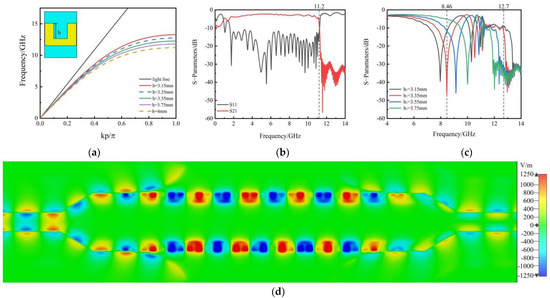
Figure 2.
(a) Dispersion curves of the U–shaped unit structured with respect to groove depths on the SSPP waveguide; (b) Black and red lines represent the reflection (S11) and transmission (S21) coefficients of the SSPP waveguide at h1 = h2 = 4 mm, respectively; (c) Simulated S21 amplitude curves of the SSPP-based MZI with h2 = 4 mm, h1 changes from 3.15 to 3.75 mm in steps of 0.2 mm; (d) Simulated near-electric-field distribution of the device at 8.46 GHz.
To consider how geometric parameters of the measured sample measured by the vector network analyzer (VNA, Agilent N5230C) can influence the functionality of an MZI sensor based on SSPPs, we investigate the impact of the thickness and permittivity of the detected sample on sensibility. Figure 3a shows the test results of the frequency shift when the thickness is the sole variable. When ε of standard MUT = 2.2, we simulate the S−parameters as shown in Figure 3a, where the thickness values of the measured sample are 0.5 mm, 1 mm, and 1.5 mm. We also assess the sensibility using the frequency shift because of the rise in the relative dielectric constant. As shown in Figure 3a, the frequency shifts are approximately 0.255 GHz, 0.435 GHz, and 0.54 GHz. It can be concluded that the frequency shift of the fundamental frequency correlates with the MUT thickness when the MUT thickness is less than 1.5 mm. The larger the thickness, the higher the sensitivity. Furthermore, we find that the permittivity of the MUT wafer affects the sensitivity of the dielectric sample during sensing. In this study, h1 = 3.35 mm, and an MUT thickness of 1.0 mm in the SSPP waveguide was selected as the basic structure of the sensor, and simulation and experimental tests were carried out for five materials, namely, air, ε = 1.0; RT5880, ε = 2.2; RO4003C, ε = 3.38; RO4350B, ε = 3.48; and Kappa 438, ε = 4.38, as shown in Figure 3b. RT5880 is a glass-microfiber-reinforced PTFE composite for transmitting the surface wave on microstrip lines and SSPP waveguides with lower losses. RO4003C is a ceramic laminates/glass reinforced hydrocarbon for the frequency radio circuit. According to the simulation results, at a fundamental frequency of 8.46 GHz, the designed sensor structure can detect the MUT with a permittivity range from 1 to 4.38 and can be sensitively evaluated on the basis of frequency shifts caused by the increase in the dielectric constant. Its frequency shift variations are all within the visual range, enhancing the feasibility of the observation and experimental measurement.
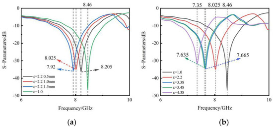
Figure 3.
(a) Simulated S21 amplitude curves of different thicknesses where the ε of the standard MUT is 2.2; (b) Simulation results for different permittivities with an MUT thickness of 1 mm.
3. Fabrication and Measurements
To confirm the aforementioned simulation results and prove the sensing performance of the MZI based on SSPPs, we fabricate a dielectric sample, as shown in Figure 4a. The thickness of the MUT wafer is 1 mm, with a diameter of d = 13 mm. Figure 4b shows the measured S21 curves. As shown in Figure 3b and Figure 4b, the amplitude variation of the simulated S21 curve is in conformity with that of the measured S21 curve. However, the overall interference frequency of the measured results is low, which may be due to the manufacturing error of the physical sensor. The total frequency shift values obtained from the measurement and simulation are 0.94 GHz and 1.11 GHz, respectively, and the difference between them is only 0.17 GHz. The data shown in Figure 4b are presented in Table 1.
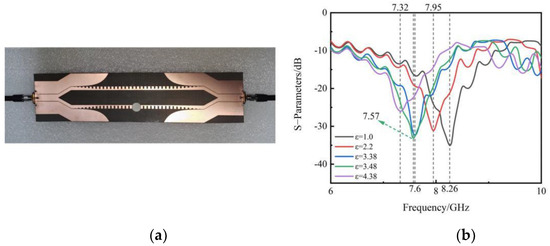
Figure 4.
(a) Actual fabricated sample; (b) Measured S–parameters under diverse capacitances.

Table 1.
Error analysis of calculated and actual permittivities.
Existing resonant sensors [30,31] can be evaluated based on their permittivity through variations in the resonant frequency. The resonant frequency approximates the permittivity utilizing a parabolic equation, which is described as follows:
The sensor designed in this study also satisfies this equation, and the changes in the interference frequency can also be represented by the permittivity. According to Table 1, by substituting the values for RO4003C, RO4350B, and Air into Equation (5), A1, A2, and A3 are obtained, and the parabolic equation of the sensor is obtained, as shown in Equation (6). Here, is the measured interference frequency, ε is the permittivity of the MUT wafer, and A1, A2, and A3 are polynomial constants.
By transforming Equation (6), the following equation is obtained, which characterizes the permittivity using the measured frequency.
By substituting the measured interference frequency of the corresponding MUT in Table 1, the error between the calculated permittivity and actual permittivity is obtained. The values are listed in Table 1. Through a comparative analysis, it is found that the calculated permittivity is close to the actual permittivity of the MUT. RT5800 and Kappa438 are verified using Equation (7), and the errors are 1.59% and 2.03%, respectively. The error analysis of the calculated permittivity and measured permittivity shows that the average error of the sensor is only 0.77%, indicating that the sensor has a high sensitivity and precision.
4. Conclusions
In this paper, the sensing feasibility of an MZI structure based on an SSPP waveguide is verified by full-wave simulations and experimental measurements. We investigate the dispersion curves and transmission capability of the design under different capacitances. The dispersion curves with respect to the groove depths are calculated to obtain the fact that the cut-off frequency increases when the groove depth height is reduced. As the groove depths of two arms in the MZI system are h2 = 4 mm and h1 = 3.35 respectively, the working frequency of the designed sensor is 8.46 GHz, and the transmission coefficient (S21) reaches −46.6 dB. According to the geometric parameters of the measured sample, we observe how the variations in the permittivity and thickness of the detected samples affect the sensibility. We fabricate a dielectric sample to verify the sensing performance, finding the amplitude variation of the simulated result is in conformity with that of the measured result. The experimental results show that the average error of the sensor is only 0.77%, and therefore, the designed sensor is highly accurate. The proposed sensor is expected to be applied in microwave integrated circuits and systems and can be extended to other frequency bands by changing the size in the design.
Author Contributions
Y.Z. Conceptualization and Writing—original draft; Y.L. investigation and methodology; H.X. formal analysis and software; T.M. writing—review and editing and resources; G.Z. project administration. All authors have read and agreed to the published version of the manuscript.
Funding
This work is funded by the National Key Research and Development Program of China (Grant No. 2021YFB3200100), the Applied Basic Research Project of Shanxi Province (Grant No. 202303021211328), the Scientific and Technological Innovation Programs of Higher Education Institutions in Shanxi (Grant No. 2021L369), the Shanxi Scholarship Council (Grant No. 2020-135), and the Yungang Special Fund of Shanxi Datong University (Grant Nos. 2020YGZX003 and 2020YGZX004).
Conflicts of Interest
The authors declare no conflict of interest.
References
- Harvey, A.F. Periodic and guiding structures at microwave frequencies. IEEE Trans. Microw. Theor. Tech. 1960, 8, 30–61. [Google Scholar] [CrossRef]
- Barnes, W.L.; Dereux, A.; Ebbesen, T.W. Surface plasmon subwavelength optics. Nature 2003, 424, 824–830. [Google Scholar] [CrossRef] [PubMed]
- Xu, X.G.; Ghamsari, B.G.; Jiang, J.H.; Gilburd, L.; Andreev, G.O.; Zhi, C.; Bando, Y.; Golberg, D.; Berini, P.; Walker, G.C. One-dimensional surface phonon polaritons in boron nitride nanotubes. Nat. Commun. 2014, 5, 4782. [Google Scholar] [CrossRef] [PubMed]
- Foley, J.J.; McMahon, J.M.; Schatz, G.C.; Harutyunyan, H.; Wiederrecht, G.P.; Gray, S.K. Inhomogeneous surface plasmon polaritons. ACS Photonics 2014, 1, 739–745. [Google Scholar] [CrossRef]
- Pendry, J.B.; Martín-Moreno, L.; Garcia-Vidal, F.J. Mimicking surface plasmons with structured surfaces. Science 2004, 305, 847–848. [Google Scholar] [CrossRef]
- Hibbins, A.P.; Evans, B.R.; Sambles, J.R. Experimental verification of designer surface plasmons. Science 2005, 308, 670–672. [Google Scholar] [CrossRef] [PubMed]
- Navarro-Cía, M.; Beruete, M.; Agrafiotis, S.; Falcone, F.; Sorolla, M.; Maier, S.A. Broadband spoof plasmons and subwavelength electromagnetic energy confinement on ultrathin metafilms. Opt. Express 2009, 17, 18184–18195. [Google Scholar] [CrossRef] [PubMed]
- Shen, X.P.; Cui, T.J. Planar plasmonic metamaterial on a thin film with nearly zero thickness. Appl. Phys. Lett. 2013, 102, 211909. [Google Scholar] [CrossRef]
- Ma, H.F.; Shen, X.; Cheng, Q.; Jiang, W.X.; Cui, T.J. Broadband and high-efficiency conversion from guided waves to spoof surface plasmon polaritons. Laser Photonics Rev. 2014, 8, 146–151. [Google Scholar] [CrossRef]
- Pan, B.C.; Liao, Z.; Zhao, J.; Cui, T.J. Controlling rejections of spoof surface plasmon polaritons using metamaterial particles. Opt. Express 2014, 22, 13940–13950. [Google Scholar] [CrossRef]
- Gao, X.; Zhou, L.; Yu, X.Y.; Cao, W.P.; Li, H.O.; Ma, H.F.; Cui, T.J. Ultra-wideband surface plasmonic Y-splitter. Opt. Express 2015, 23, 23270–23277. [Google Scholar] [CrossRef] [PubMed]
- Jia, Y.Y.; Ren, J.; Zhang, Q.; Zhang, H.C.; Liu, Y.Q.; Li, Y.B.; Wan, X.; Cui, T.J. Frequency-Controlled Broad-Angle Beam Scanning of Patch Array Fed by Spoof Surface Plasmon Polaritons. IEEE Trans. Antennas Propag. 2016, 64, 5181–5189. [Google Scholar]
- Xiao, B.; Chen, J.; Kong, S. Filters based on spoof surface plasmon polaritons composed of planar mach–Zehnder interferometer. J. Mod. Opt. 2016, 63, 1529–1532. [Google Scholar] [CrossRef]
- Moreno, E.; Rodrigo, S.G.; Bozhevolnyi, S.I.; Martín-Moreno, L.; García-Vidal, F.J. Guiding and focusing of electromagnetic fields with wedge plasmon polaritons. Phys. Rev. Lett. 2008, 100, 023901. [Google Scholar] [CrossRef] [PubMed]
- Zhang, H.C.; Liu, S.; Shen, X.; Chen, L.H.; Li, L.; Cui, T.J. Broadband amplification of spoof surface plasmon polaritons at microwave frequencies. Laser Photonics Rev. 2015, 9, 83–90. [Google Scholar] [CrossRef]
- Huang, T.; Zeng, S.; Zhao, X.; Cheng, Z.; Shum, P. Fano resonance enhanced surface plasmon resonance sensors operating in near-infrared. Photonics 2018, 5, 23. [Google Scholar] [CrossRef]
- Yanik, A.A.; Huang, M.; Kamohara, O.; Artar, A.; Geisbert, T.W.; Connor, J.H.; Altug, H. An optofluidic nanoplasmonic biosensor for direct detection of live viruses from biological media. Nano Lett. 2010, 10, 4962–4969. [Google Scholar] [CrossRef] [PubMed]
- Yin, L.; Vlasko-Vlasov, V.K.; Pearson, J.; Hiller, J.M.; Hua, J.; Welp, U.; Brown, D.E.; Kimball, C.W. Subwavelength focusing and guiding of surface plasmons. Nano Lett. 2005, 5, 1399–1402. [Google Scholar] [CrossRef] [PubMed]
- Fang, N.; Lee, H.; Sun, C.; Zhang, X. Sub-diffraction-limited optical imaging with a silver superlens. Science 2005, 308, 534–537. [Google Scholar] [CrossRef] [PubMed]
- Li, Y.; Kang, M.; Shi, J.; Wu, K.; Zhang, S.; Xu, H. Transversely divergent second harmonic generation by surface plasmon polaritons on single metallic nanowires. Nano Lett. 2017, 17, 7803–7808. [Google Scholar] [CrossRef] [PubMed]
- De Hoogh, A.; Opheij, A.; Wulf, M.; Rotenberg, N.; Kuipers, L. Harmonics generation by surface plasmon polaritons on single nanowires. ACS Photonics 2016, 3, 1446–1452. [Google Scholar] [CrossRef] [PubMed]
- Cui, W.Y.; Zhang, J.; Gao, X.; Zhang, X.; Cui, T.J. Passive amplitude-phase modulations and sensing based on Mach-Zehnder interferometer of spoof surface plasmon polaritons. J. Opt. 2021, 23, 075101. [Google Scholar] [CrossRef]
- Heideman, R.G.; Kooyman, R.P.H.; Greve, J. Performance of a highly sensitive optical waveguide Mach-Zehnder interferometer immunosensor. Sens. Actuators B 1993, 10, 209–217. [Google Scholar] [CrossRef]
- Blanco, F.J.; Agirregabiria, M.; Berganzo, J.; Mayora, K.; Elizalde, J.; Calle, A.; Dominguez, C.; Lechuga, L.M. Microfluidic-optical integrated cmos compatible devices for label-free biochemical sensing. J. Micromech. Microeng. 2006, 16, 1006–1016. [Google Scholar] [CrossRef]
- Gao, Y.; Gan, Q.; Xin, Z.; Cheng, X.; Bartoli, F.J. Plasmonic Mach-Zehnder interferometer for ultrasensitive On-Chip biosensing. ACS Nano 2011, 5, 9836–9844. [Google Scholar] [CrossRef]
- Zhao, X.; Mazumder, P. Bio-sensing by Mach-Zehnder interferometer comprising doubly-corrugated spoofed surface plasmon polariton (DC-SSPP) wave guide. IEEE Trans. THz Sci. Technol. 2012, 2, 460–466. [Google Scholar]
- Kashif, M.; Bakar, A.A.A.; Hashim, F.H. Analysing surface plasmon resonance phase sensor based on Mach-Zehnder interferometer technique using glycerin. Opt. Commun. 2016, 380, 419–424. [Google Scholar] [CrossRef]
- Wang, J.; Zhao, L.; Hao, Z.C.; Shen, X.; Cui, T.J. Splitting spoof surface plasmon polaritons to different directions with high efficiency in ultra-wideband frequencies. Opt. Lett. 2019, 44, 3374–3377. [Google Scholar] [CrossRef]
- Cui, W.Y.; Zhang, J.; Gao, X.; Cui, T.J. Reconfigurable Mach–Zehnder interferometer for dynamic modulations of spoof surface plasmon polaritons. Nanophotonics 2022, 11, 1913–1921. [Google Scholar] [CrossRef]
- Lim, S.; Kim, C.Y.; Hong, S. Simultaneous measurement of thickness and permittivity by means of the resonant frequency fitting of a microstrip line ring resonator. IEEE Microw. Wirel. Compon. Lett. 2018, 28, 539–541. [Google Scholar] [CrossRef]
- Samad, A.; Hu, W.D.; Shahzad, W.; Raza, H.; Ligthart, L.P. Design of highly sensitive complementary metamaterial-based microwave sensor for characterisation of dielectric materials. IET Microw. Antennas Propag. 2020, 14, 2064–2073. [Google Scholar] [CrossRef]


Publisher’s Note: MDPI stays neutral with regard to jurisdictional claims in published maps and institutional affiliations. |
© 2022 by the authors. Licensee MDPI, Basel, Switzerland. This article is an open access article distributed under the terms and conditions of the Creative Commons Attribution (CC BY) license (https://creativecommons.org/licenses/by/4.0/).