1. Introduction
In remote areas and particularly in the sub-Saharan territories, the low population distribution causes difficulties in ensuring on-site health coverage in emergency cases requiring medical evacuation, such as the Coronavirus Disease 2019 (COVID-19) pandemic [
1,
2]. Therefore, mobile hospitals are needed to be built or deployed in the desert and remote areas. These hospitals include different medical treatment and diagnostic equipment, which are essentially required in medical emergency [
3]. The smooth operation of these medical devices requires a continuous power supply from diesel generators, which result in high fuel costs and preventive maintenance [
4,
5].
In remote areas with high solar potential, the combination of a diesel generator (DG) with photovoltaic (PV) generators offers better energy services in terms of reduced operating costs and achievement of gradual transition from fossil to renewable sources [
6,
7]. In case of low demand, excess energy from PV generators needs to be stored using energy storage systems. However, some medical devices may require high peak power, and batteries suffer from a short life span due to suddenly high energy requirements (5–10 years) and low dynamic behavior [
8]. However, peak power demand can be supported by ultracapacitors due to their high power density capability [
9,
10]. The management of all these generation sources and storage systems presents a major challenge in determining the relationship between energy production and consumption in a mobile hospital. In this context, there are few research studies in the literature that address this problem [
11]. The profile of electrical energy consumption is illustrated in an isolated hotel where its consumption is pre-determined according to the number of clients or visits during the year [
12]. On the other hand, the authors in [
13] have proposed a model for distributing the energy produced between different departments of a hospital while minimizing the energy cost. In the same context, the resiliency of a hospital is studied in [
14] by optimizing the sizing of its generation sources. The hospital is powered by renewable energy and a conventional generation source. The techno-economic potential of hybrid power generation systems is studied for refugee camps and rural areas [
15,
16]. Nonetheless, all these studies do not consider a mobile hospital, which is needed in the case of medical emergencies.
For medical emergencies, the reliability of a hybrid power generation system for mobile hospitals is also important. In this regard, the mean time between failure (MTBF) of different generators, converters, and wirings plays a vital role in determining reliability for continuous energy supply to critical applications like mobile hospitals [
17]. In case of DG failure, the main backup source has been lost for mobile hospitals. Hence, MTBF of DG must be incorporated at the planning and sizing stages of hybrid power generation systems for mobile hospitals [
18,
19]. Moreover, an inverter source can also be added as a redundant power supply on each floor to ensure a reliable power supply for mobile hospitals.
The integration of different production and storage systems for mobile hospitals requires an efficient energy management strategy. Many papers have proposed microgrid applications that are designed for autonomous operation, where the main control objective is to know how to manage the energy flow between the different loads of the system. In the microgrid framework, various control strategies have been proposed in the literature. A frequency-based power-sharing method is presented in [
20] to mitigate the effect of weather or sea state variations on the integrated onboard ship microgrid. A hybrid energy storage system (HESS) based on ultracapacitor and battery is developed such that high power and short-term fluctuations are handled by the battery and ultracapacitor. Proportional integral derivative (PID) and proportional derivative (PD) based control methods are introduced in [
21] for the smooth operation of hybrid power generation under steady-state and dynamic operating conditions, respectively. In [
22], the power balance control is achieved for a multi-source microgrid hybrid system to meet the DC load power demand while ensuring DC bus voltage stabilization. In the same context, Ref. [
23] proposes a coupling structure of the DG on the DC bus side to slow down the power dynamics produced by the DG and ensure the efficiency and profitability of the system by operating the DG around its rated power. A voltage and frequency control strategy is developed in [
24] for a renewable power generation system. An inverter interfaced energy storage system is connected with an AC bus instead of a conventional generator to regulate system frequency.
Most of the energy management techniques presented above require the DG to remain operational most of the time for avoiding transition regimes of operating modes. In [
25,
26], a transition control strategy between the connected and disconnected modes of the grid was proposed for a three-phase voltage source based on the calculation of reference powers and a virtual impedance control strategy to achieve efficient power distribution in the hybrid energy storage elements, where the battery provides steady-state power and supports only transient power fluctuations.
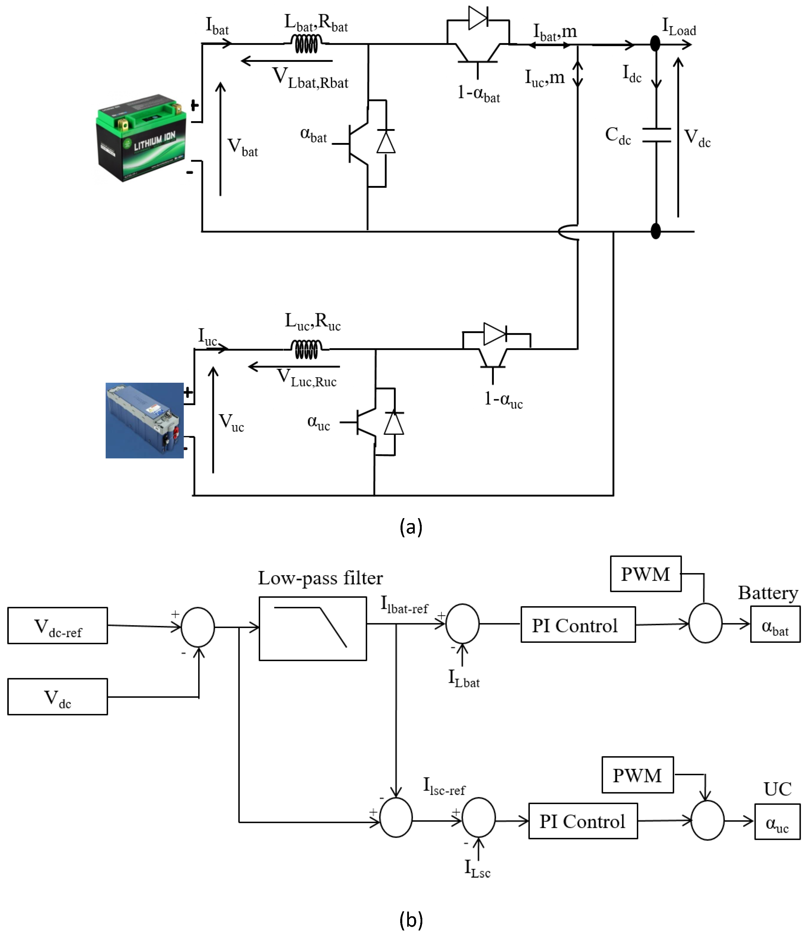
This paper proposes a new energy flow supervision for a PV-diesel-HESS microgrid that efficiently manages the operation of generation and storage systems in different operating modes. For PV system management, it is connected with a boost converter to operate in either maximum power tracking mode or power curtailment (Off-MPPT) mode. The battery is connected to a bidirectional DC-DC converter, which regulates the DC bus voltage and controls the state of charge (SOC) of the battery. The ultracapacitor is also included with the batteries to compensate for peak power demand. The diesel generator is connected in parallel with the PV generator, battery, and ultracapacitor to provide the insufficient power required by the load. For the efficient operation of all these generation sources and storage systems, an energy management algorithm is developed to manage the energy flow between the sources and load through effective control of power converters.
2. Power Sizing of Mobile Hospital
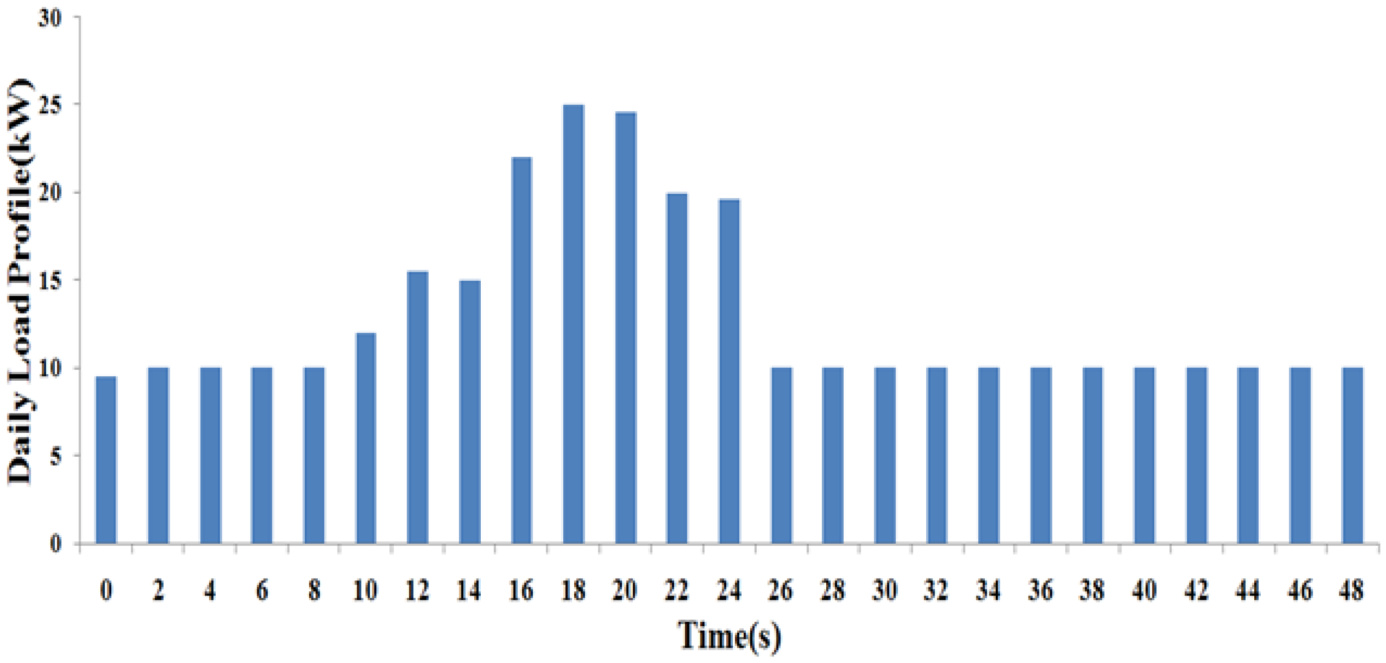
Table 1 presents a list of medical and non-medical equipment with their estimated daily energy needs according to their power consumption priority. In hybrid power system designing, the proper sizing of each source is important. It must be efficiently determined such that the continuous power supply is ensured for smooth energy availability at a lower cost. The sizing depends on both the location-dependent meteorological characteristics and the required load demand. A typical daily load profile of a mobile hospital is shown in
Figure 1.
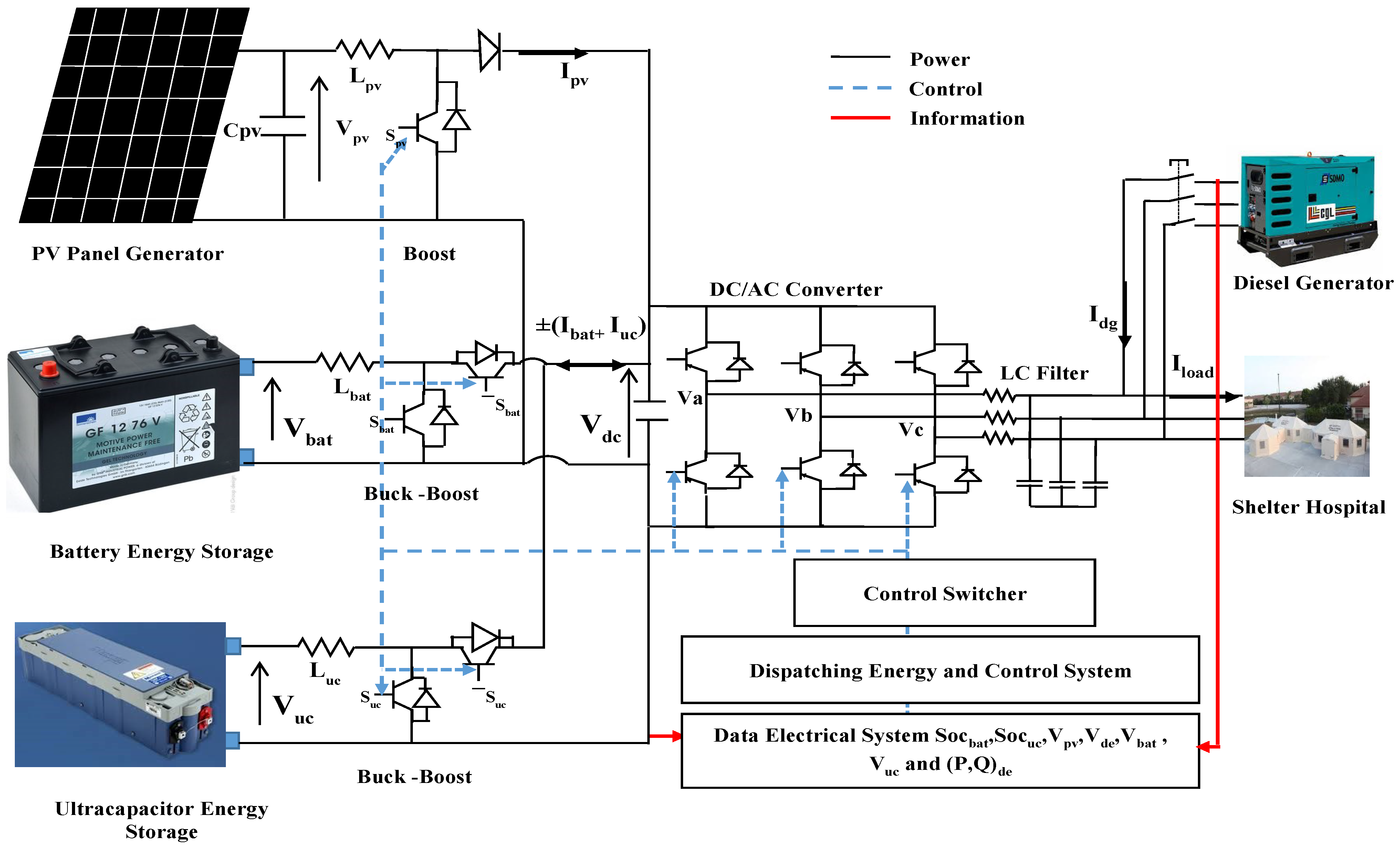
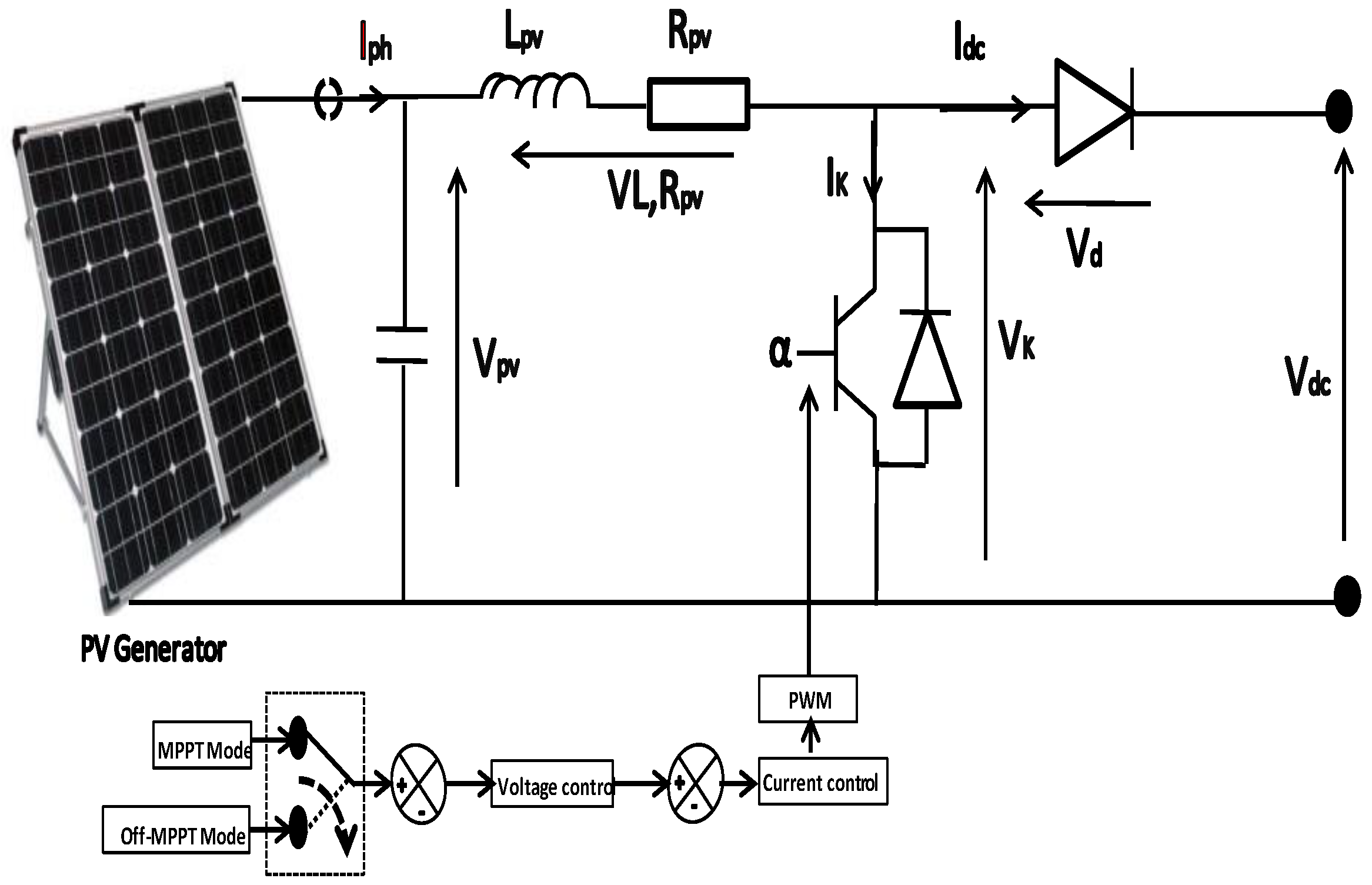
The hybrid power system is presented in
Figure 2. It is composed of a photovoltaic generator as a renewable energy source, battery, ultracapacitor, diesel generator as a source of emergency energy, and power electronics converters as elements of electric power exchange of energy flow in the system. PV generator is connected with a boost converter. However, the battery and ultracapacitor are connected to bidirectional DC-DC converters. The diesel generator is connected in parallel with the DC bus through a bidirectional inverter while it is directly connected with the AC load.
During the design, the sizing of the power appears as an important aspect. It must be done in such a way as to ensure a continuous power supply while ensuring energy availability at a lower cost. The sizing depends on both the meteorological characteristics depending on the location and the required load demand. However, this paper focuses only on proposing energy management and control structure for the hybrid power system of a mobile hospital.
5. Power Management Strategy
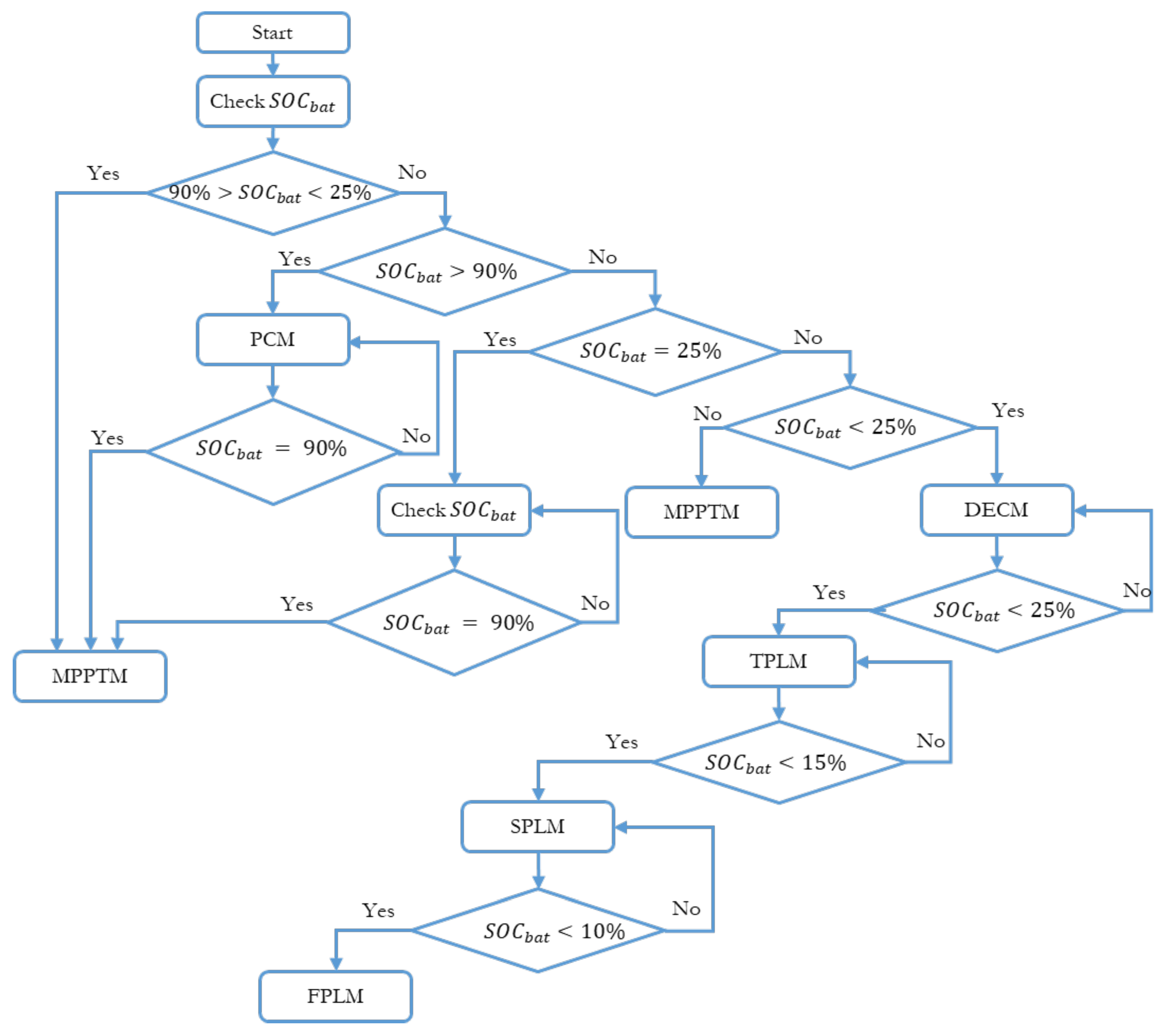
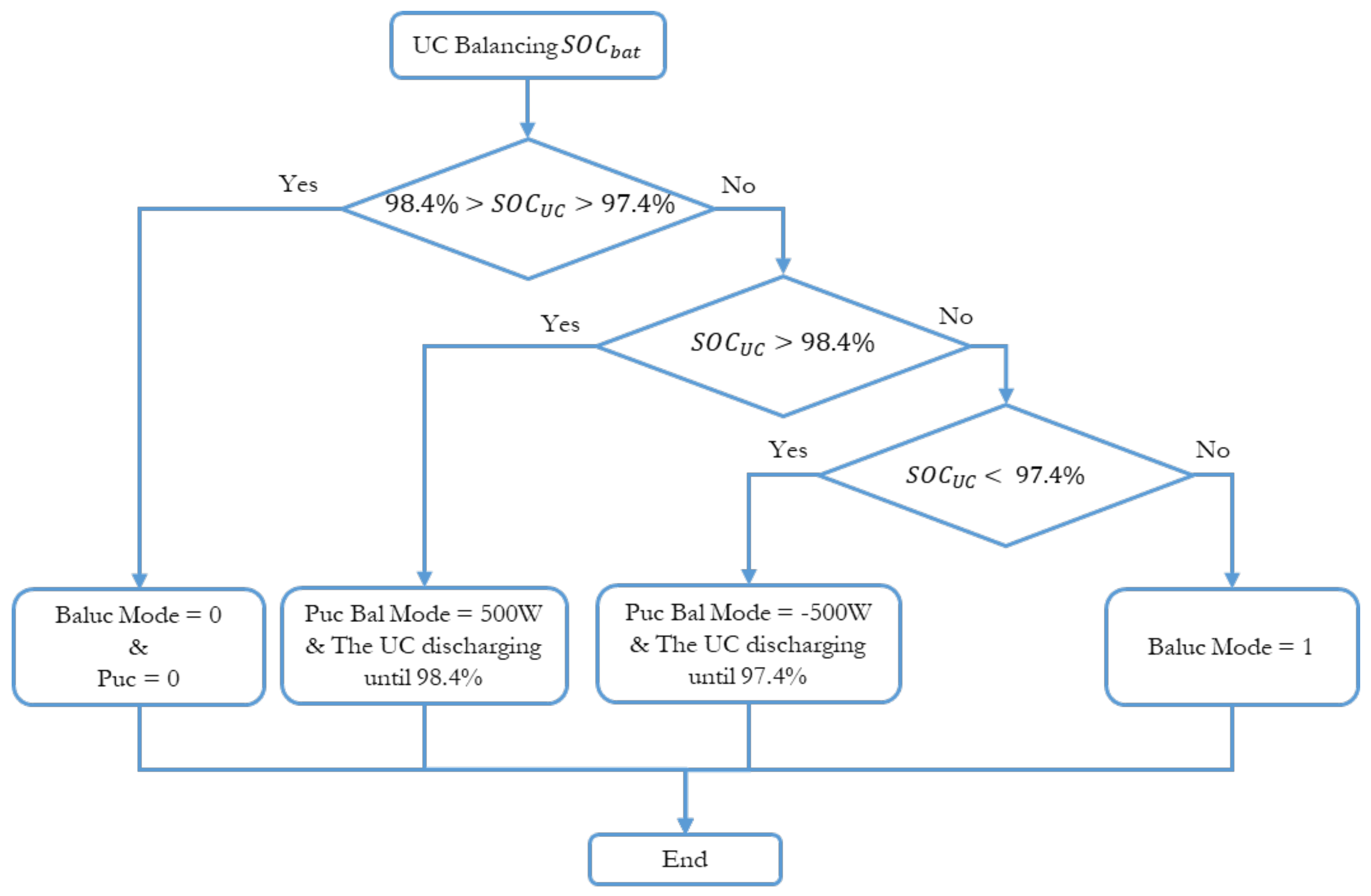
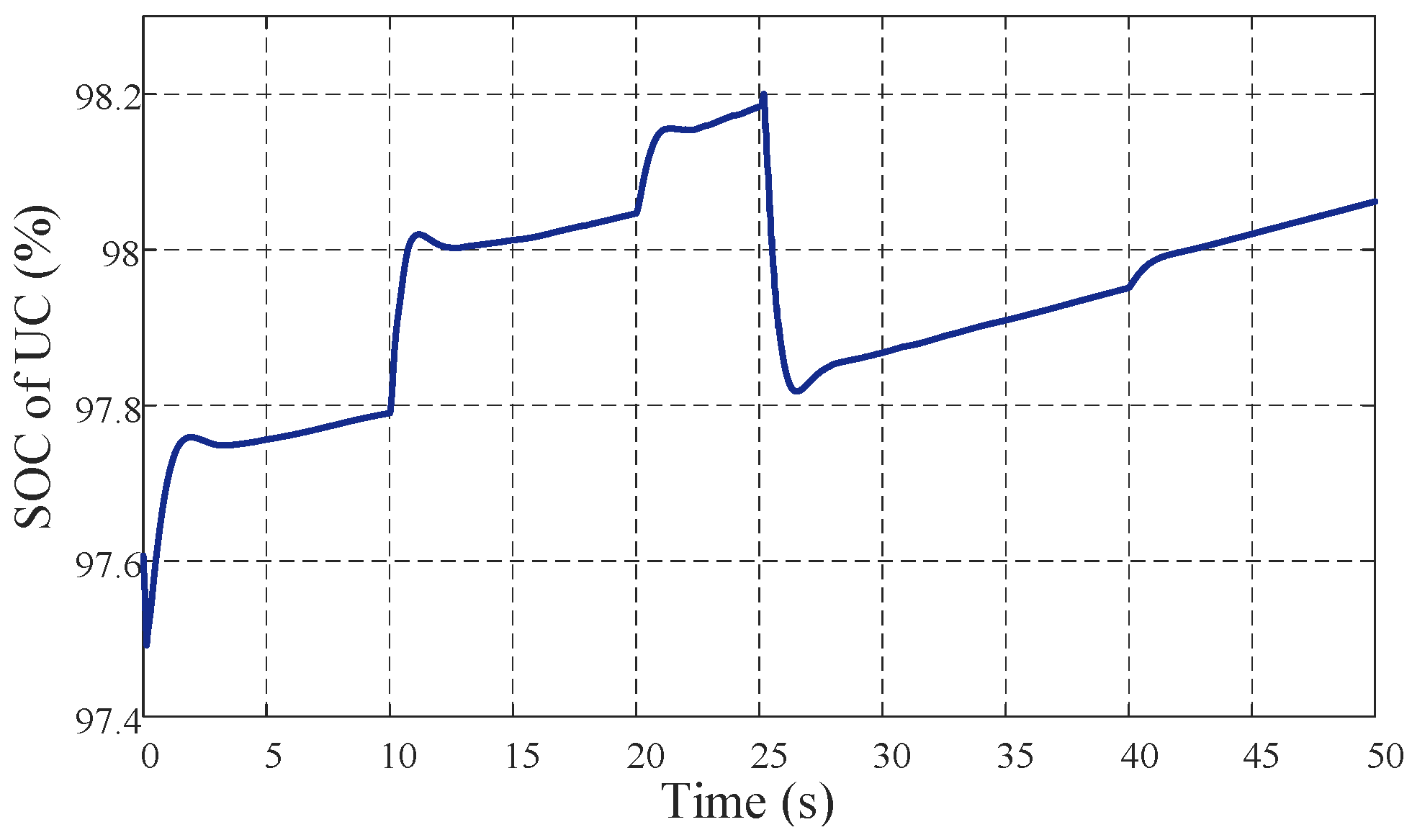
Power management and sharing in the electrical system are developed according to the state of charge and discharge of the battery storage system. In this case, the ultracapacitor state of charge is kept between 97.4% and 98.4%. The proposed power management strategy of the battery is illustrated by
Figure 14, while
Figure 15 illustrates the ultracapacitor level balancing algorithm.
The proposed power management strategy contains seven operating modes as presented in
Table 2.
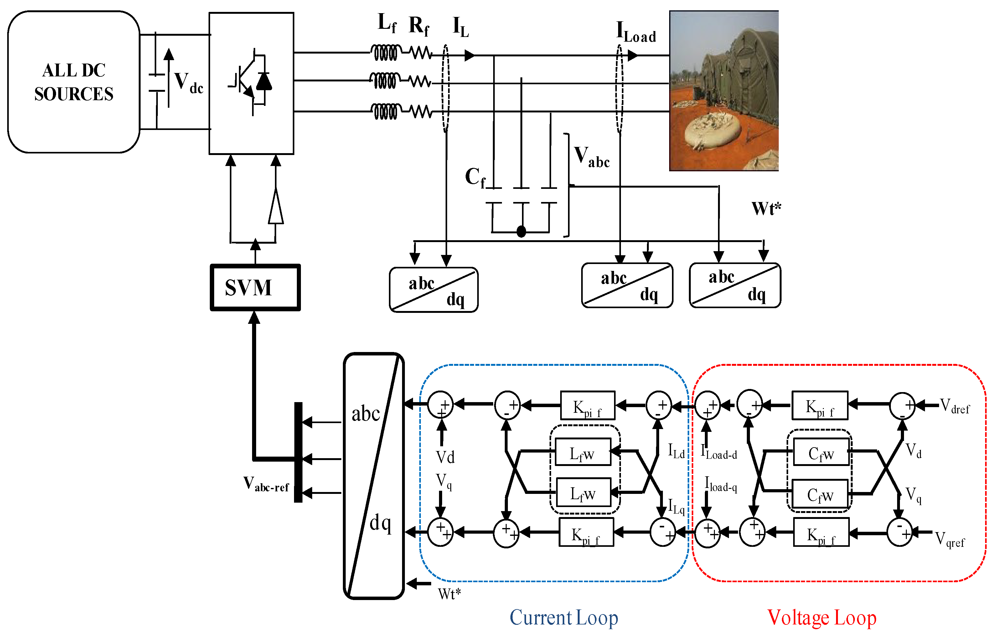
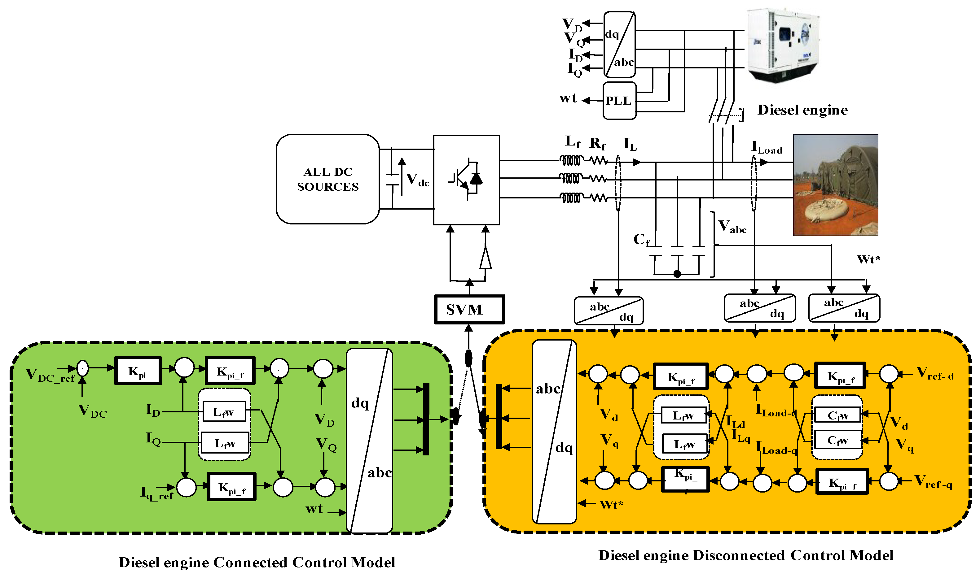
5.1. Diesel Engine Disconnected Mode (DEDM)
This mode is activated when battery SOC is greater than 25% (). In this case, the PV generator operates either in MPPT mode or in Off-MPPT (Power Curtailment). Therefore, it has two sub-modes: power curtailment mode (PCM) and MPPT mode (MPPTM).
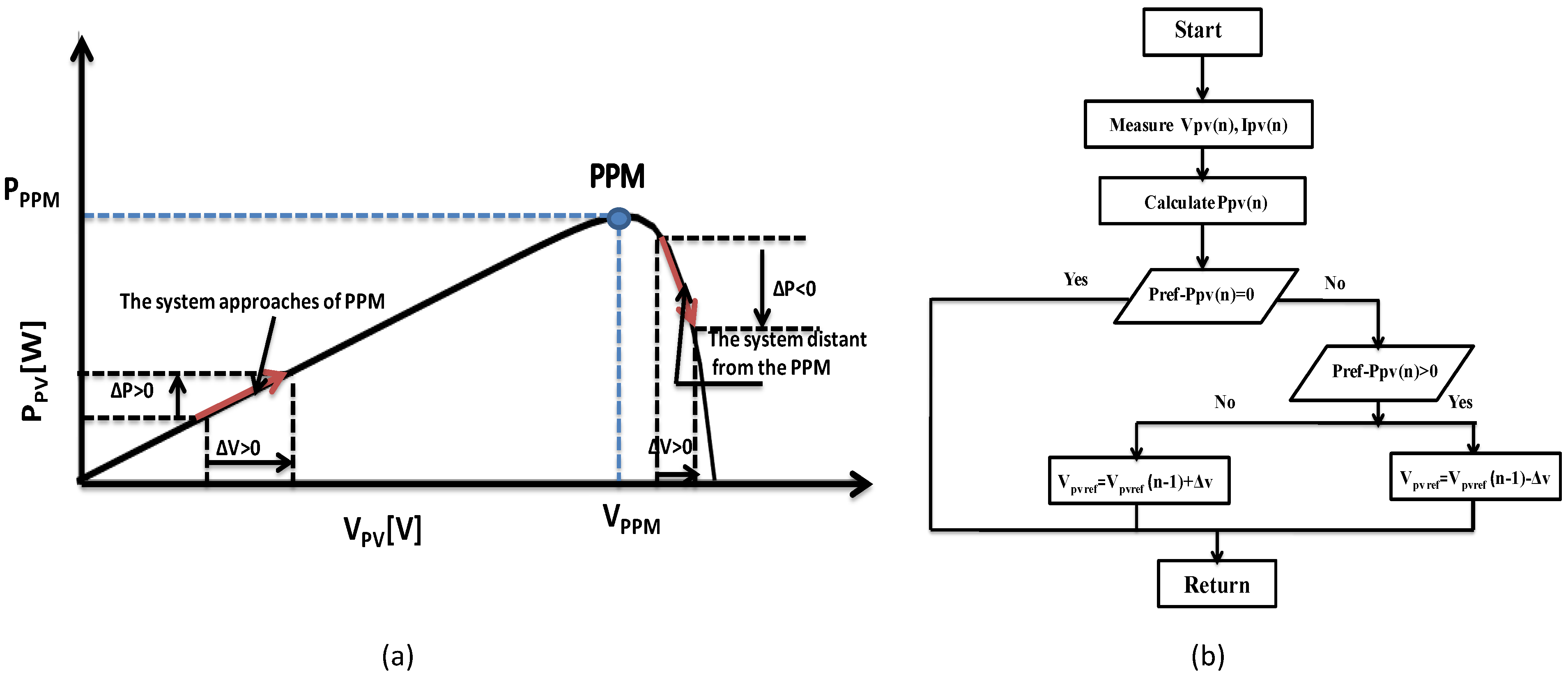
5.1.1. Power Curtailment Mode (PCM)
This operating mode is selected when the power of the photovoltaic generator meets the total load demand and the two storage elements are fully charged i.e., (
), The PV power must be limited to a reference value lower than
(Maximum PowerPoint). The control algorithm enabling PCM is illustrated by
Figure 9b.
5.1.2. Maximum Power Point Tracking Mode (MPPTM)
This mode is activated when the state of charge of the battery is less than the maximum permissible state (). In this case, the PV generator operates in MPPT mode to extract the maximum amount of electrical energy depending on the climate conditions. The storage elements have the possibility of absorbing or compensating to keep the DC bus around its value of reference V, the diesel generator is stopped, and all loads are connected.
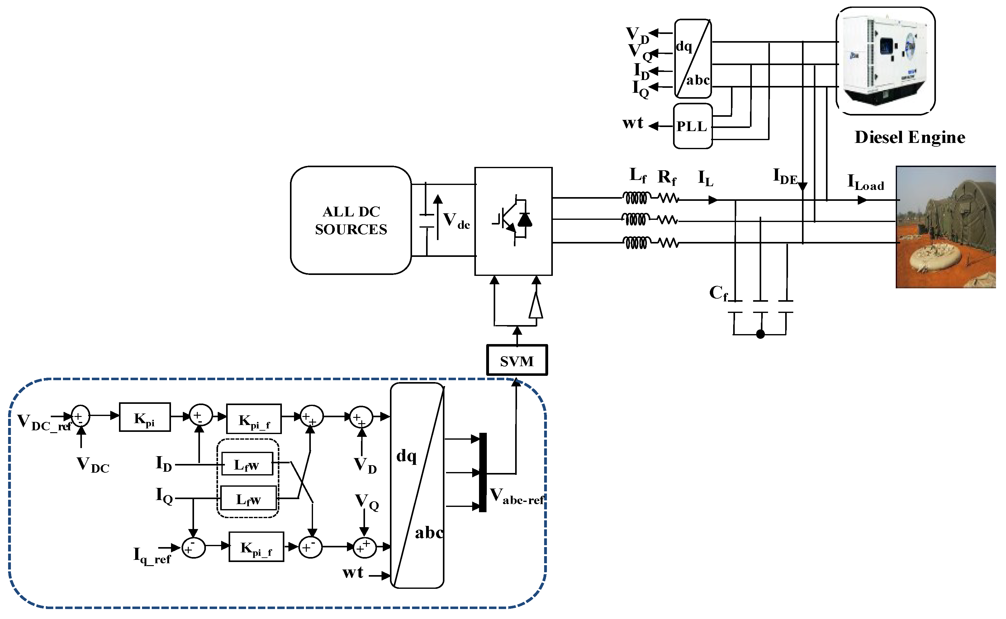
5.2. Diesel Engine Connected Mode (DECM)
This mode is selected when the state of charge of the battery pack is equal to 25%. In this case, the diesel generator operates at its nominal power in parallel with the PV in MPPT mode and charges the storage elements up to 90%.
5.3. First Priority Load Mode (FPLM)
When the Diesel generator is operating alone and the state of charge of the batteries and the ultracapacitor is insufficient and continues to charge (weak climatic conditions) below 10%, the system will be unable to satisfy the main load (load P1). In this case, the load must be disconnected to allow the hybrid storage device to charge.
5.4. Second Priority Load Mode (SPLM)
If the state of charge of the hybrid storage is between 10% and 15% (), the load with the second priority (load P2) will be disconnected and only the load with the priority (load P1) will remain connected.
5.5. Third Priority Load Mode (TPLM)
This mode is activated when the operation of the diesel generator is connected and when the state of charge of the batteries is below 25% but remains above 15%. To avoid an additional discharge of the batteries, the supervision algorithm will disconnect the load with the lowest priority (P3).
6. Results and Discussion
To validate the proposed power management strategy, the following system and mode parameters are adopted:
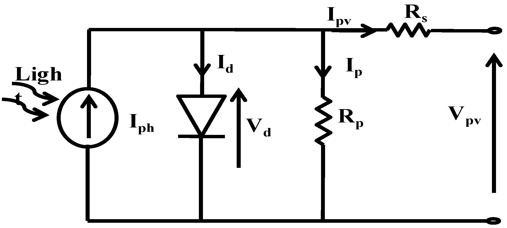
Table 3 provides parameters of PV generator and
Table 4 summarizes DC system parameters. AC source parameters are given in
Table 5. The controller parameters for both grid-connected and off-grid modes of the hybrid power system are provided in
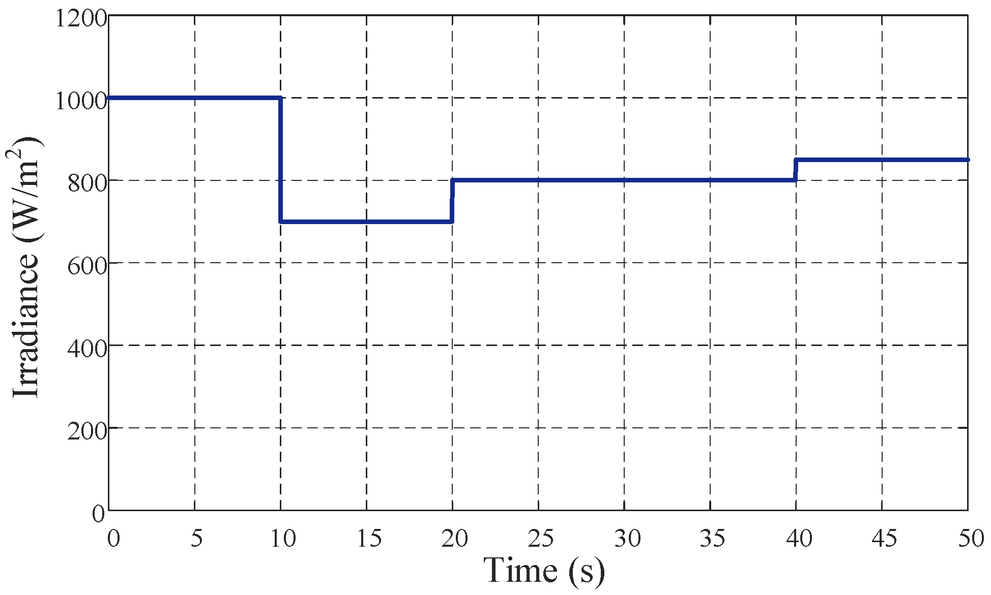
Table 6. The solar irradiance profile is shown by
Figure 16.
DC bus voltage, as shown in
Figure 17, is clearly following its reference (700 V). For regulation of the DC bus voltage
, the inverter intervenes by absorbing the surplus current to inject it into the storage sources and discharge the ultracapacitor until
= 700 V. In steady-state, the voltage across the DC bus remains constant due to fast dynamic voltage regulator that maintains it at its reference value (
= 700 V). Few disturbances have been observed in DC bus voltage at
t = 10 s, 20 s, and 25 s with change in operating modes, which are happened due to sudden changes in PV power generation and load requirements.
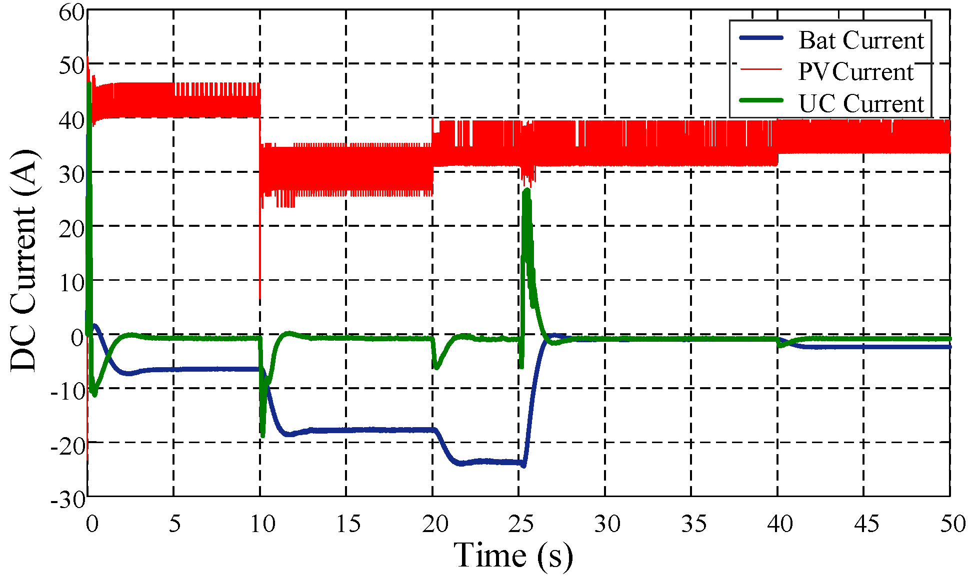
Figure 18 and
Figure 19 show the DC power and current outputs of PV generator, battery storage, and ultracapacitor following proposed power management strategy under sudden changes in irradiance and load profiles. The ultracapacitor is rapidly balancing power demand mismatch at balancing at
t = 10 s, 20 s, and 25 s. It should be noted that the DC sources quickly meet system requirements in terms of power demand in both DC and AC buses. Different operating modes of the system start with the MPPT mode at 0.10 s.
When , PV generator supplies the required power to load and the power surplus will be stored in both battery and ultracapacitor.
With low PV power output and increase in load demand (
G = 700 W/m
2,
P = 25 kW), DG intervenes and the DECM mode is activated at
t = 10 s to ensure continuous power supply to the load while also charging the battery. At instant
t = 25 s, the storage system is sufficiently charged and the requested load demand is satisfied which leads to the switch to the PCM mode. DG is also disconnected from the hybrid power system, as combination of PV and hybrid storage systems are enough to meet the load demand. At instant
t = 40 s and after a slight disturbance, the MPPT mode is activated again and the battery begins recharging.
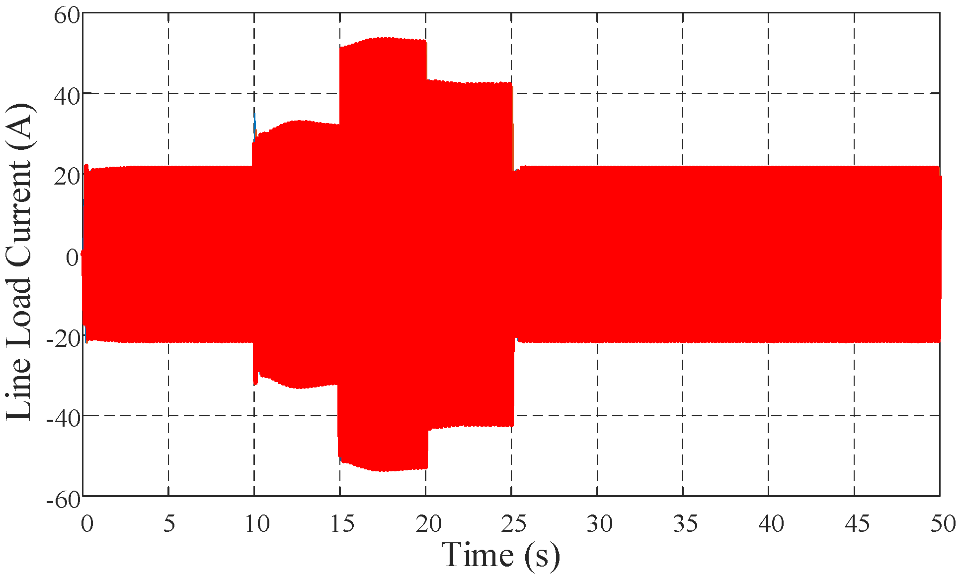
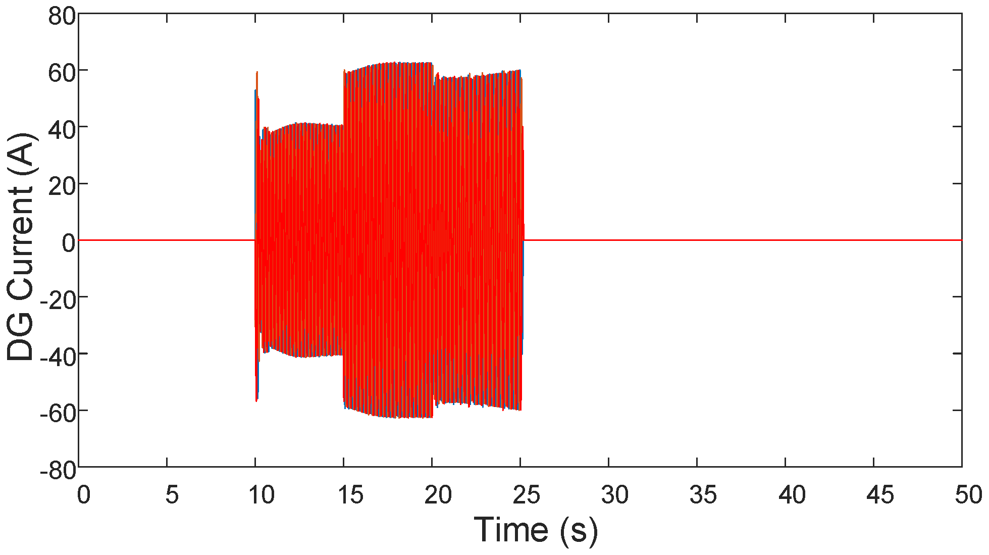
Figure 20 and
Figure 21 present the current profiles of load and DG, respectively. Load is increased between
t = 10 s to 25 s, DG connects to the system to meet the load demand during this period because DC power generation and storage systems are unable to meet this increasing demand.
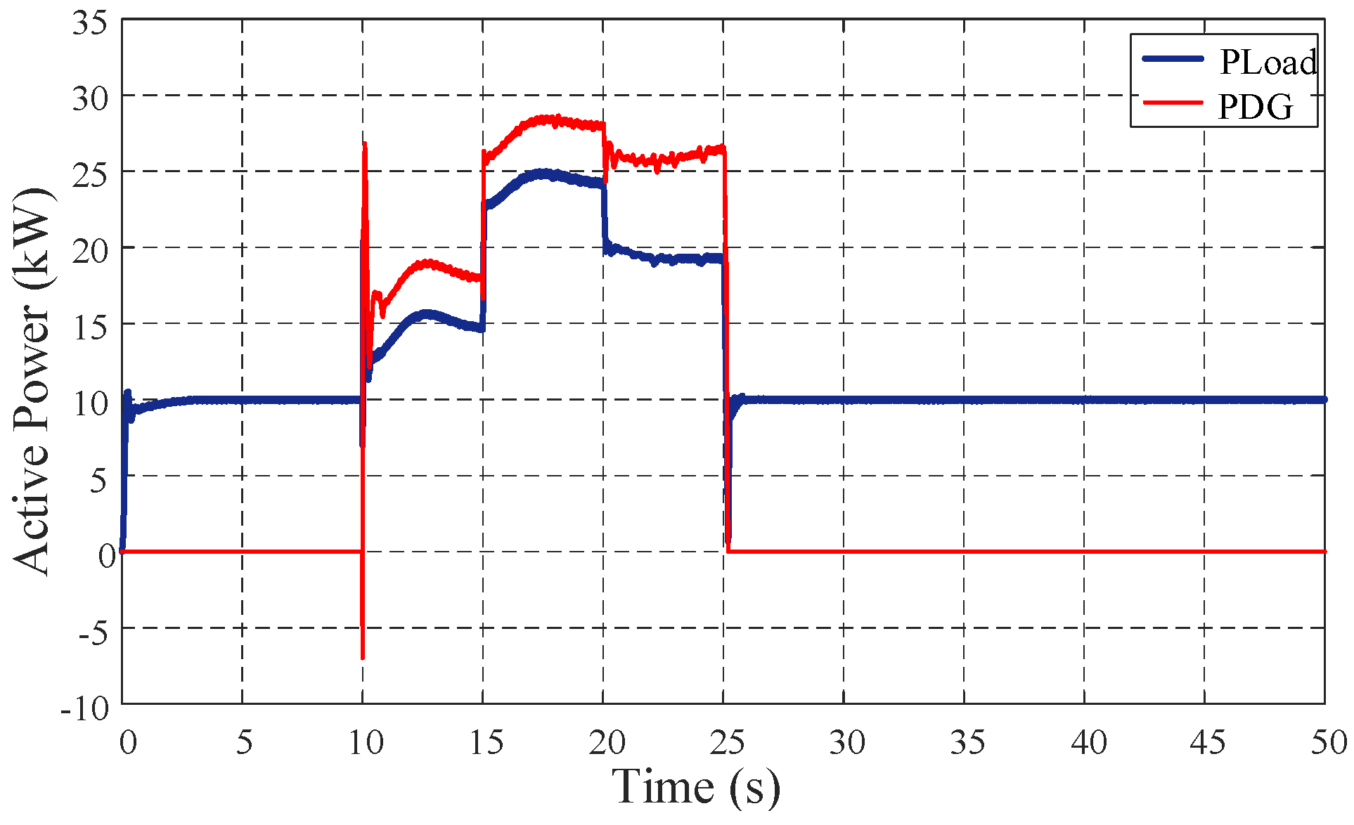
Figure 22 illustrates the two operating modes of DG disconnection and connection with the system. The specified mode appears between
t = 10 s and 25 s when active power demand is requested and it cannot be met by only DC power generation and storage systems (
). In this case, DG connects and supplies to the load in the connected mode.
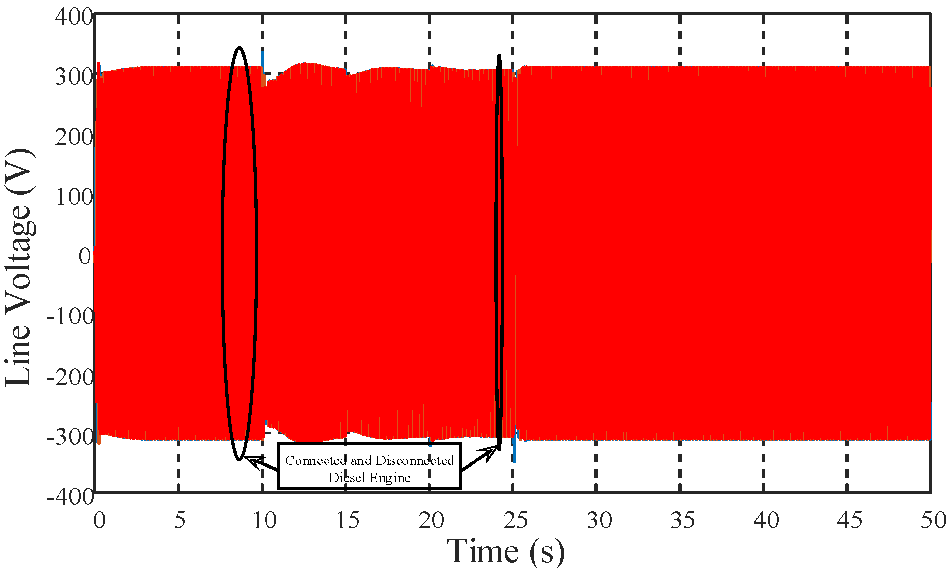
Figure 23 illustrates the case where the inverter and DG are connected with disturbances due to synchronization of the two voltage sources in the two operating modes. Due to the DG starting, voltage is provided by the inverter (disconnected mode) until
t = 13 s when the DG stabilizes.
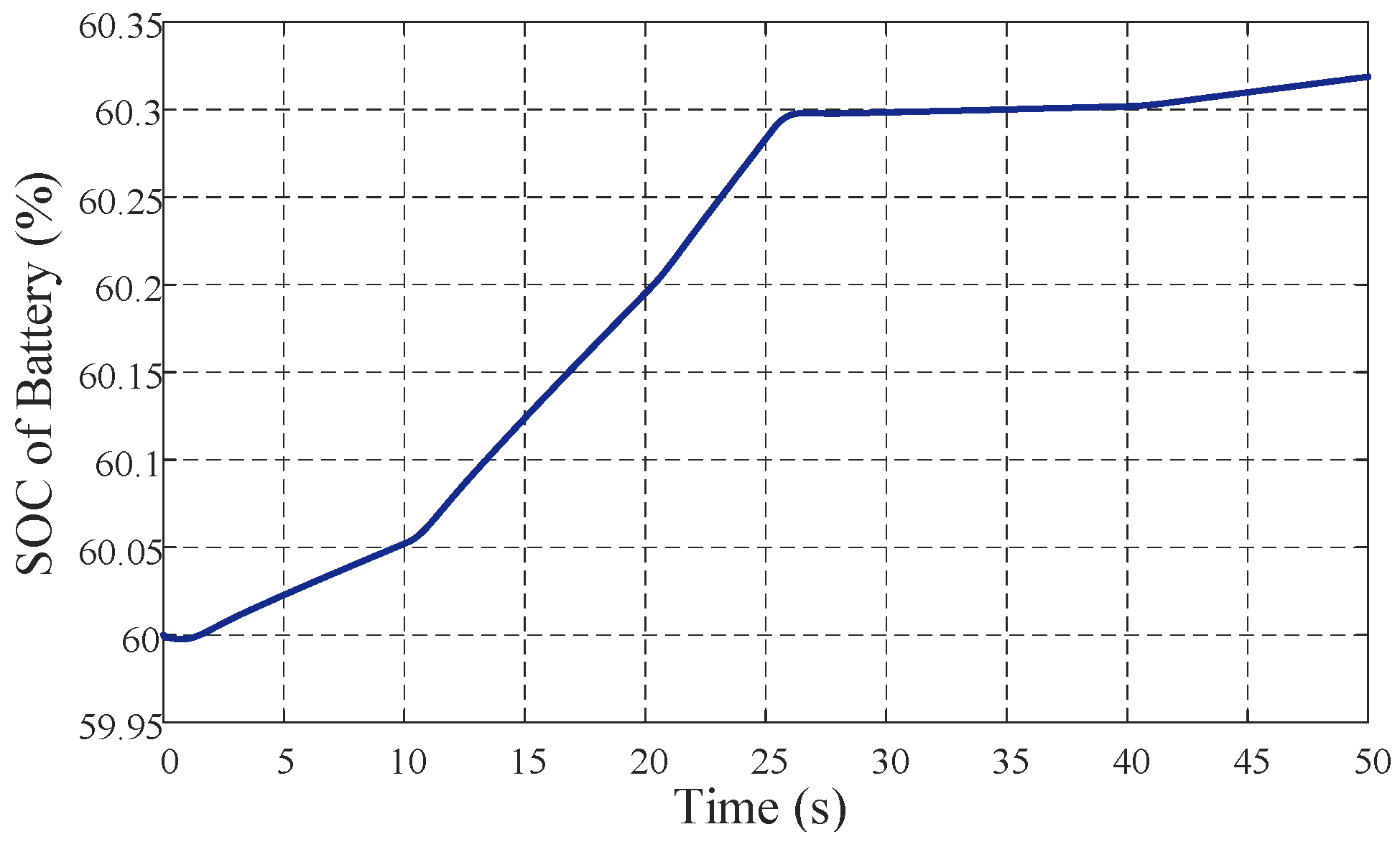
Battery and ultracapacitor
SOC levels are given in
Figure 24 and
Figure 25, respectively. Initial
SOC of battery is set at 60%. Hence PV generator operates in MPPT mode and the battery is continuously charging. It is charging a little faster when DG is also providing power. The ultracapacitor is also balancing real-time energy fluctuations like when DG is connected to the system and later disconnected from it.


 ,
, 


