1. Introduction
Nonvolatile NAND flash memories are the basic building blocks of the data storage components found in a range of systems, including IoT and edge-computing platforms, wearable electronics, smartphones, self-driving cars, and the drones to solid-state drives (SSDs) used in personal computers and cloud computing infrastructures [
1]. Energy efficiency is a key requirement for the data storage components used in emerging edge computing devices, as most of them are constrained by limited power sources [
2,
3,
4]. The designers of modern flash storage systems, such as SSDs, focus exclusively on the long-term data integrity rather than on the energy efficiency. In light of the many emerging approximate computing applications, e.g., machine learning, data analytics, vision, object classification, and others as described in [
5,
6,
7,
8], where approximate and short-lived data are very common, new opportunities have arisen for developing energy-efficient approximate storage systems [
9].
A typical flash-memory-based storage system consists of two discrete components: the flash storage media, with one or more flash memory devices, and a flash memory controller. Often the controller and the flash memory devices are made by different companies, and system integrators integrate these components to design storage solutions tailored for specific applications. Flash memory manufacturers comply with a chip-interfacing specification defined by the Open NAND Flash Interface (ONFI) working group [
10]. This specification offers few application-agnostic storage functions, which are not tailored towards energy-efficient approximate storage applications. Thus, there remain several opportunities for the system integrators to design energy-efficient storage systems by utilizing the tradeoffs between the data accuracy and the energy efficiency that are inherent to the NAND flash memory technology.
Even though NAND flash-memory-based storage solutions require less power than other nonvolatile storage solutions, e.g., hard disk drives, they still account for a significant portion of the total energy expenditures of computing systems [
11]. Several recent research proposals have emphasized the prospect of approximate storage for achieving high-energy efficiency in the emerging edge-computing applications [
11,
12,
13,
14,
15,
16,
17,
18]. To curb the energy consumption of flash memories in ultra-low-power microcontrollers, Salajegheh et al. [
18] propose an energy-saving technique utilizing lower operating voltages, which jeopardize the correct memory operations. To remedy the possible loss of information, they employed: (a) Repeated in-place write operations; (b) Multiple-places write operations; or (c) The RS-Berger coding of data. They report energy savings for in-place write operations of up to 34% on lower-end microcontrollers. Similarly, a study by Tseng et al. [
12] shows that up to 45% of the energy consumed could be saved using dynamic voltage scaling on the basis of the flash operations being performed. Sampson et al. [
14] propose an approximate storage technique in solid-state memories by relaxing the threshold voltage margins between different memory states during the write operations by using varying program pulse widths. Through detailed simulation, they show that their proposal would make the memory write 1.7 times faster. However, the implementation of their method on the common-off-the-shelf (COTS) NAND chips requires privileged commands that are not available in the ONFI command set. Li et al. [
16] propose leveraging the approximate data in the NAND flash memory to improve the read performance and enhance the reliability of regular data. Papirla et al. [
19] find that the energy required by flash write operations heavily depends on data patterns. Thus, they propose an encoding scheme that minimizes the frequency of power-hungry bit patterns in codewords (‘10’ and ‘01’), reducing the total energy of the flash write operations by up to 34%. Nath et al. [
20] propose a lazy amnesic-compression-based technique for storing data in flash memories. The required energy for the flash write operations is reduced by using a lossy compression; the compression ratio is adjusted on the basis of the age of the data. Mathur et al. introduce Capsule [
11], a log-structured object storage system for flash memories that supports the fine-grain allocation of space for storage objects, such as streams, files, arrays, and queues. Poudel and Milenkovic [
13] introduce a technique that reduces the time and energy consumed by the critical flash operations in embedded NOR memories by introducing partial or aborted flash operations.
Though these techniques demonstrate significant potential for reducing the total energy consumed, they often introduce extra overhead in time, compute resources, and/or memory space [
11,
12,
13,
14,
15,
16,
17,
18]. Moreover, they usually consider lower-density flash memories, e.g., the NOR flash memories used in low-end embedded systems [
13,
18]. Although using partial write operations is suggested by Sampson et al. [
14] as a way to increase the energy efficiency of SSDs, its effectiveness is evaluated using a simulation-based environment only, without taking into account the physical properties of COTS flash memory chips. Consequently, the effectiveness of this approach on the COTS flash memory chips remains unknown. In addition, we are not aware of any study that considers the now dominant three-dimensional (3D) NAND flash memory technology and the unique challenges it presents. For example, the timing and data integrity parameters are often layer-dependent. Thus, we believe there is a need to explore the energy efficiency of the now dominant 3D NAND flash memories, and to experimentally evaluate the effectiveness of the techniques for improving their energy efficiency.
The complex organization of NAND flash memories and their physical properties demand disproportionate latency and energy expenditures in order to ensure high data integrity when writing data into the flash memories. This paper experimentally explores this disproportionality on state-of-the-art commercial 3D NAND flash memories and introduces EXPRESS—a technique for increasing the energy efficiency of flash memory writes. EXPRESS utilizes partial program operations, thereby exploiting the disproportionality between the latency and energy expenditures on one side, and the data accuracy on the other side. The proposed method can be implemented in the storage controller’s firmware, without requiring any privileged flash operations or changes in the system design. An experimental evaluation shows that EXPRESS reduces energy expenditures by 20–50%, relative to the traditional flash writes, at the cost of minimal loss in the data integrity (<1%). In addition, the paper experimentally explores the impact of the page-to-page variability and the program–erase cycling on the implementation of EXPRESS, and it offers strategies to cope with these undesired effects. Compared to the existing techniques, EXPRESS offers the following advantages: (a) It can be applied to both 2D and 3D flash memories; (b) It does not require any privileged operations; (c) It can be combined with, and is orthogonal to, other techniques (e.g., voltage scaling); and (d) It does not require any data preprocessing or special data encoding.
Table 1 presents a comparative analysis of the major characteristics of the previously proposed related techniques and EXPRESS.
The following are the key contributions of the paper:
We explore and quantify the disproportionate trade-offs between the data accuracy and the energy efficiency of flash memory program operations, using COTS 3D NAND flash memory chips. We find that more than 20% of the energy and time is spent on improving less than 1% of the bit accuracy during the memory write operations. We shed more light on this phenomenon and identify the slow memory cells belonging to the tails of the state distributions, a main reason for the disproportionate energy–accuracy tradeoffs;
We propose a novel technique called EXPRESS, which utilizes partial write operations to increase the energy efficiency at a minimal loss of accuracy. We characterize the NAND flash operations and experimentally explore the energy–accuracy tradeoffs as a function of the partial program time. On the basis of the results of the experimental evaluation, we propose an algorithm for choosing the partial program time that strikes an optimal balance between the energy efficiency and the data accuracy;
We perform a detailed characterization of the page-to-page variability, the program–erase cycling effects, and the data retention effects on the effectiveness of EXPRESS. We propose several countermeasures that can be adopted to properly address these variability and reliability issues.
The rest of the paper is organized as follows:
Section 2 presents the background by discussing the fundamentals of 3D NAND flash memories, the flash incremental pulse programming scheme, and the flash memory interfacing;
Section 3 introduces the proposed technique;
Section 4 explores the effectiveness of the proposed technique when applied to 3D flash memories operating in the SLC (single-level-cell) and MLC (multilevel-cell) modes.
Section 4 also discusses the challenges due to the page-to-page variability, the program–erase cycling, and the data retention issues, and it offers enhancements to EXPRESS to address these challenges.
Section 5 concludes the paper.
3. Proposed Technique—EXPRESS
The EXPRESS technique reduces the energy consumed during the flash program operations, at the cost of a negligible loss of accuracy. It relies on a partial page program operation to counter the disproportionate energy–accuracy tradeoff inherent in the ISPP scheme.
Figure 4a illustrates the proposed EXPRESS technique. The solid black line represents the status of the RB pin during a regular page program operation. This pin goes low, indicating that the NAND array is busy for the duration of the program operation,
The
value lies in the range of 300–600
s for an SLC memory page of the chip used in this study [
27]. The program operation, however, can be terminated prematurely using a RESET command, such as the program suspend operation [
28]. In this case, the state of the RB pin is illustrated with the red dashed line. The premature termination of the program operation results in a partial program operation. Although this operation may slightly increase the bit error rate (BER), it can significantly reduce the time and energy of the page program operations. The critical parameter that enables an exploration of the tradeoffs between the energy and the accuracy is the partial program time,
. The following equation can be used to estimate the
:
Here, is the number of program cycles that can be skipped to achieve higher energy efficiency. Note that we have not included the verification phase of the last program cycle in Equation (2), as no additional bits are programmed during the verification phase. In general, Equation (2) can be used as a guideline for finding an optimal , which needs to be precharacterized on the basis of the properties of the particular family of flash memory chips.
Figure 4b sheds more light on the rationale behind EXPRESS by illustrating three different reference voltages, which correspond to three different memory operations. The erase operation ensures that the threshold voltages of all the erased cells in the block are below the reference voltage,
. Similarly,
is the reference voltage used during the program verification phase of the page program operation. The ISPP scheme ensures that the threshold voltages of all the programmed cells are above the reference voltage,
. Finally, a read reference voltage,
, is used to distinguish between the erase and program states of the cell during a page read operation. All NAND manufacturers keep a sufficient voltage margin between the read and program verification voltages in order to minimize read errors. However, this margin can be exploited to increase the energy efficiency in all applications where the BER is sufficiently low and it can be corrected using error-correction techniques. In addition, EXPRESS can be used even when a somewhat higher BER can be tolerated, e.g., in applications where approximate short-lived data are common. For example, if we terminate the program operation prematurely, the resulting threshold voltage distribution will be mostly above the read reference voltage, as is shown with the dashed lines in
Figure 4b. The resulting distribution may have some area below the read reference voltage and that will create errors, which we are trading off for the saved energy.
Since 3D NAND flash memory cells in the erased state exhibit long tails of the threshold voltage distribution, programming these cells may require several extra program pulses. Since left-tail cells usually represent less than 1% of the total page size, a premature termination of the program operation may cause just 1% of cells to have threshold voltages below Interestingly, not all of these tail bits will show up as error bits during a read operation, as there is a sufficient voltage margin between the read and the program verification voltages. Thus, one can improve the energy efficiency of flash memory program operations with very little, or no, sacrifice in the bit accuracy if the partial program time is chosen appropriately. However, such partial programming may lead to increased retention loss because of the reduced reliability margin. The following section presents the experimental evaluation of the energy–accuracy tradeoffs in the state-of-the-art 3D NAND flash memory. It formulates guidelines for choosing the appropriate partial program time.
4. Experimental Evaluation
In our experimental evaluation, we use a 3D NAND flash memory chip that supports both the SLC and MLC modes of operation.
Section 4.1 describes our experimental setup.
Section 4.2 and
Section 4.3 describe the results of the experimental evaluation of EXPRESS for the SLC and MLC modes, respectively. Whereas EXPRESS promises energy savings at a negligible loss of accuracy, it is important to address any practical issues that can impact the efficacy of the proposed technique, including the page-to-page variability, the wear-out of the gate oxides, and the data retention. Hence,
Section 4.4 discusses the effects of the page-to-page variability and the PE cycling on EXPRESS.
Section 4.5 discusses the long-term effects of the EXPRESS mechanism on data retention. Finally,
Section 4.6 puts everything together with a real-world example.
4.1. Experimental Setup
Figure 5 shows our experimental setup, which consists of a TSOP-48 socket that holds a flash memory chip, an FT2232H mini module from Future Technology Devices International (FTDI), and a workstation. The FT2232H module acts as a bridge between the workstation and the device, implementing an asynchronous 8-bit parallel interface to the device, as described in
Figure 3. A software package running on the workstation executes the ONFI commands for sending data to the flash memory chip, erasing a block, writing a page, reading a page, or retrieving the data from the device. This hardware setup allows us to access raw memory bits without any error correction. We used a logic analyzer and a Digilent Analog Discovery II multifunction instrument to measure the time and capture the voltage samples from a shunt resistor connected to the power line of the TSOP socket. We performed the experimental evaluation on several 3D NAND MLC chips, with the following properties: the chip capacity is 256 Gbits; the number of blocks is 2192; each block contains 1024 pages; and each page contains 18,592 bytes of data (16,384 bytes of user data, with 2208 spare bytes reserved for storing out-of-band information, such as error correction codes). The chip was manufactured using 32-layer 3D technology.
4.2. Evaluation of the Proposed Technique on SLC Memory
We first validate EXPRESS by configuring a NAND chip to operate in the SLC mode. An all-zero data pattern is written using partial-page program operations while varying the partial program time,
. Later, in
Section 4.4, we perform a similar experiment with a random data pattern with an equal distribution among all the available flash cell states.
Figure 6a shows the percentage of the programmed bits as a function of the partial program time. Each point in the plot represents the percentage of programmed bits collected from 10 experiments on the same page. Each partial program experiment is proceeded by a full block erase operation.
Figure 6b shows the current drawn by the NAND chip during a regular page program operation. The corresponding status of the RB pin during a regular page program operation is illustrated by a red dashed line. The current drawn increases notably during the program operation relative to the current drawn in the device’s idle state. The current waveform reveals two distinct profiles, which are repeated alternatively. We hypothesize that these characteristic current profiles correspond to the program (blue-shaded regions), and that they verify (red-shaded regions) the phases of the page program operation and its ISPP scheme.
The plot in
Figure 6a shows that the percentage of programmed bits resembles a step function. The flash memory cells are programmed only during program pulses. The transition points of the percentage of programmed bits align with the program pulse phases in
Figure 6b. Furthermore, the percentage of programmed bits remains constant during the verification phases. This confirms our hypothesis that the ISPP scheme is used in a page program operation, and that the characteristic waveforms correspond to the program pulses and verify the phases of the page program operation.
Furthermore, the results from
Figure 6 support the following two observations:
- 1.
Figure 6a shows that just three program cycles out of five used in a regular program operation are sufficient to achieve a bit accuracy above 99.9%. The last two program pulses are mainly used to program a tiny fraction of bits located in the lower tail of the erase
distribution, as illustrated in the inset of
Figure 6a;
- 2.
Figure 6b illustrates that there is periodicity in terms of the program and verification cycles, and that all program pulses and verification phases have similar duration and current profiles. Thus, Equation (2) can be used for determining a suitable partial program time. As there is no tangible advantage in the termination of the program operation in the middle of a verification or a program cycle, the optimal
should correspond to the end of a program pulse. The number of program pulses required to achieve the desired bit accuracy may be specific for a family of chips, the location of the page in the 3D structure, and its usage conditions. Still, all of these can be precharacterized and then used to inform a proper implementation of the partial program operations.
4.3. Evaluation of the Proposed Technique on MLC Memory
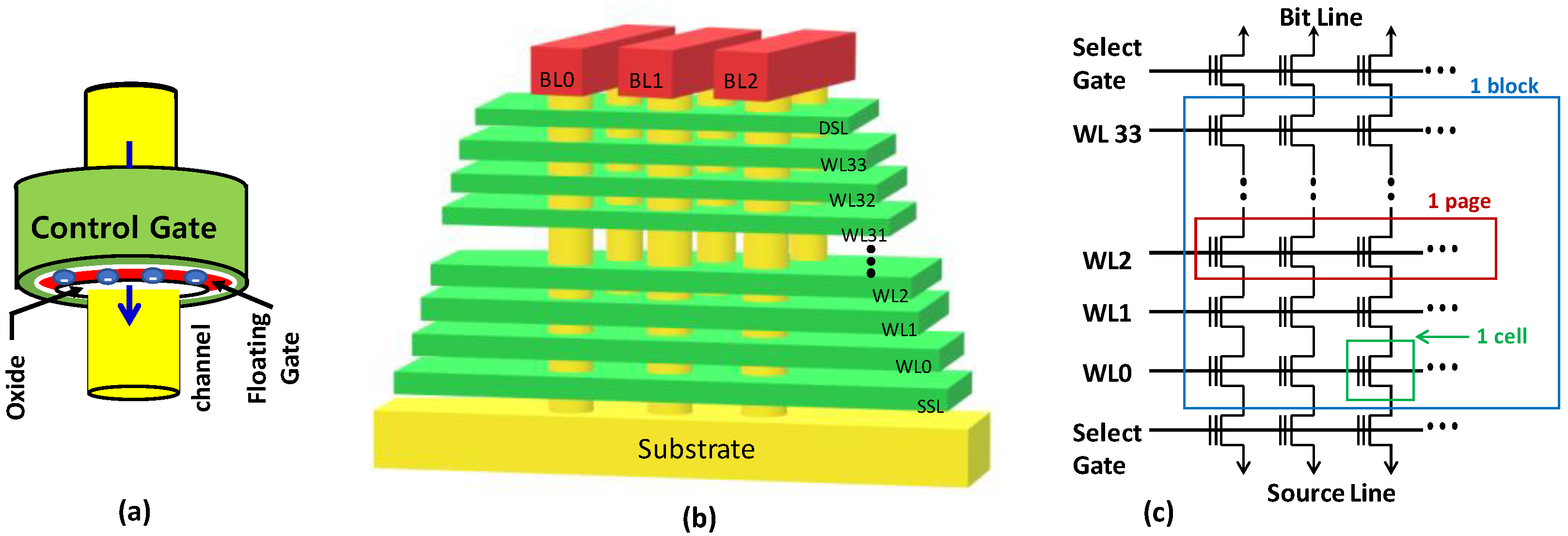
MLC flash memory cells store 2 bits of information, and, hence, there are two different types of logical pages sharing a single word line. These two bits correspond to four states of the flash memory cells, i.e., the information is encoded in the form of four threshold voltage distributions (Er-11, A-01, B-00, C-10), as illustrated in
Figure 7. The most significant bit (MSB) of the logic states of all the memory cells connected to a given word line forms the MSB page. Similarly, the least significant bit (LSB) of the logic states of the memory cells from the same word line forms the logical LSB page. The LSB page programming involves raising the erase state (
) of certain cells to the B-state, as is shown in
Figure 7. The MSB page programming is performed after the LSB page programming is finished. During MSB page programming, certain memory cells from the Er state go to the A state, and certain cells from the B state go to the C state, as is shown in
Figure 7. Two read reference voltages are used to read the MSB page data, whereas only one read reference voltage is needed for reading the LSB page data.
Figure 8a shows the percentage of programmed bits as a function of the
for the MSB and LSB pages in the red and blue solid lines, respectively. The experiments are conducted as follows: Logical LSB and MSB pages are used from a freshly erased block. First, we partially program an LSB page, and then the corresponding MSB page, with an all-zero data pattern. Please note that the chip used in this study, when configured in the MLC mode, by default implements data scrambling, which ensures that all four states are uniformly utilized in a physical page, regardless of the input data pattern. Thus, writing all zeros in the LSB and MSB pages does not imply that all the cells are in the B state. Therefore, the data pattern does not impact the results of our experiments, as demonstrated later in
Section 4.4, where we use random data patterns. After the partial program operation, we perform the page read operation for both the LSB and MSB pages, and we determine the percentage of programmed bits for each experiment. The programmed bit percentage for the LSB pages looks quite similar to the one observed for the SLC mode of operation. Since writing on an LSB page involves only one programmed
state (B state), its ISPP scheme is quite similar to the one used in the SLC mode.
However, the programmed bit percentage for the MSB pages has distinctively different characteristics. There are two plateaus because two different states, A and C, are formed during MSB programming. The first plateau corresponds to the construction of the A state, as it has a lower , and is thus formed first. The second plateau corresponds to the formation of the C state. The time to complete an MSB page program operation is significantly longer than the time needed to program the corresponding LSB page. As the programming of an MSB page involves transitioning the flash cells from Er to A, and from the B to C states, it thus requires more ISPP cycles and, consequently, more time to complete a program operation, relative to its LSB counterpart. Another distinctive feature of the MSB page programming is its verification phases, which are more complex than the LSB counterparts. An LSB page verification requires only one read to verify that the cell exceeds the lower bound of the B state (), whereas an MSB page verification requires two reads to check the lower bounds of both the A and C states. These hypotheses are confirmed by inspecting the current profiles, as discussed in the text below.
Figure 8b,c shows the current drawn by the chip during a page program operation for an LSB page and an MSB page, respectively. Similar to the SLC current profiles, we observe the periodic program pulses and verify the phases in the current waveform. For example, the LSB page, analyzed in
Figure 8b, requires nine ISSP cycles, with the total program time,
. However, the bit accuracy reaches above 99% with only seven program pulses (
), indicating a 25% energy saving with a <1% bit accuracy loss. Programming MSB pages generally requires more time than programming LSB pages. For example, the MSB page analyzed in
Figure 8c requires
,
ISPP cycles. In addition, the verification phases in the case of MSB program operations take more time than those that take place during LSB program operations. Still, we find that partial program operations can be utilized on MSB pages, offering more than 20% in energy savings, with a negligible (<1%) bit-accuracy loss. The optimal partial program time for MSB pages is
.
We observe considerable page-to-page variability in the bit accuracy (error bar in
Figure 8a), even though the
was fixed. Such page-to-page variability may arise in the NAND memory because of the inherent process variations, physical organization, and the presence of program and read noise. In the next section, we elaborate further on the page-to-page timing variability and the possible countermeasures.
4.4. Effects of Page-to-Page Variability
3D NAND flash memories exhibit page-to-page variations because of the unique nature of the array geometry and the intrinsic process variations within the array.
Figure 9a shows the organization of a 3D NAND memory block configured in the SLC mode. The pages in a block are organized in rows that correspond to the physical vertical layers (
) and columns that correspond to the sub-blocks (
). A page number within a block can be expressed as
, where
represents the layer number, and
. The chip under evaluation has 32 layers (
) where each layer contains 16 logical pages (
) of a given memory block. Thus, there are a total of 16 × 32 = 512 pages within a block. We performed a characterization of the page program times by sequentially programming all of the pages of a memory block using a random data pattern. Our characterization results are shown as a cumulative distribution plot in
Figure 9b. The results indicate that the standard-page program time varies significantly among different pages within the same block. Since the implementation of EXPRESS requires an estimation of the
on the basis of the nominal page program time (
), it needs to be adapted in order to account for the page-to-page variability.
To understand the precise nature of the page-to-page variability, we measure each page’s nominal page program time in a block in SLC mode.
Figure 10 shows the results of these measurements. We can make the following two observations from these results:
- a.
The first page to be programmed in a given layer takes more time to complete a program operation. We classify these pages as “slow” pages, shown in blue in
Figure 10;
- b.
The variability is minimal among memory pages located in the same vertical layer () of the array. Consequently, we argue that the memory controller can learn the value from the page, (referred to as a “learning” page), and then apply EXPRESS when programming the remaining pages.
To further illustrate the variability, we compute the median
as the last column in
Figure 10. We find that the median
varies between different layers, but within the same layer, the
remains relatively unchanged (except the first page of a layer). We exploit this observation and propose an adaptive learning algorithm to maximize the energy savings for the EXPRESS method.
To address the observed variabilities, we propose the following modification to EXPRESS. The nominal program time variation among slow pages (marked as blue boxes in
Figure 10) is minimal. Consequently, the flash controller may apply EXPRESS on the slow pages by learning the corresponding
from the first page of the block (
). The remaining pages of the block are classified as learning pages (yellow) and EXPRESS pages (green). The nominal page program operations are performed on the learning pages to acquire the exact
value, and EXPRESS is applied on the remaining pages of the layer (
) by estimating the corresponding
using Equation (2).
Next, we discuss the page-to-page variability for a flash block configured in the MLC mode.
Figure 11a shows the cumulative distribution of
for the LSB and MSB pages. We find significant page-to-page variability for both the LSB (blue line) and MSB (red line) pages. LSB pages behave similarly to the SLC pages, where the first LSB page of a given layer requires significantly longer
, compared to the other LSB pages in the same layer. These slow LSB pages constitute the upper tail (~10%) of the cumulative distribution in
Figure 11a. The average
for the MSB pages is distinctively higher than the average
for the LSB pages. Unlike the LSB pages, the
variability for the MSB pages is relatively small. The first MSB pages in a layer do not require a higher
than the other MSB pages in the given layer.
Since LSB pages behave similarly to SLC pages, the algorithm for implementing EXPRESS on LSB pages can mirror the algorithm proposed for the SLC pages, as described above. For the MSB pages, a slight modification of the algorithm is introduced by treating the first MSB page (
) in a given layer as the learning page.
Figure 11b shows the EXPRESS algorithm for MSB pages where the
is learned from the first MSB page of a given layer,
. Equation (2) is used to estimate the
from the corresponding
, and that value is applied to the remaining
(
n =1, 3, …, 15) pages. Next, we will discuss the energy benefits obtained with these algorithms when implemented in the 3D NAND chip under evaluation.
The adaptive learning algorithm for EXPRESS widens the opportunity window for performance and energy enhancement.
Table 2 summarizes the measured
(or nominal program time of a page), and the corresponding optimal
, for pages in both the SLC and MLC configurations. The table also quantifies the effectiveness of EXPRESS by reporting the bit error rate and the average percentage of energy saved. The results are broken down on the basis of the page types, as discussed above. We calculate the number of program loops that can be skipped for EXPRESS to acquire an acceptable accuracy loss (<1%) for each page type. We find an optimal value of the parameter,
, in Equation (2):
for SLC pages, depending on their type, and
for MLC pages. For higher values of the
, the BER in the written data is found to be more than 1%. However, the
needs to be precharacterized for each class of chips for optimal EXPRESS implementation. Note that the table is prepared on the basis of data collected from 1024 pages of an MLC flash block, and from 512 pages of an SLC flash block. We find that EXPRESS can save an average of 20 to 50% of the write energy, depending on the page type, whereas the exact figure for energy savings may differ for flash memory chips that have a different organization, or that are manufactured in different technology nodes. The proposed technique applies to all of them because it exploits the accuracy–energy disproportionality that is common for all modern flash memory chips.
4.5. Effects of Program–Erase Cycling on EXPRESS
NAND flash memory exhibits limited endurance, which is typically specified by the maximum number of program–erase operations (or PE cycles) allowed on a memory block. The number of PE cycles may impact the nominal page program time,
, and stressed pages with a high number of PE cycles may take more time to program [
29,
30,
31]. Hence, an implementation of EXPRESS needs to consider the number of PE cycles.
Figure 12a shows the cumulative distribution of the nominal page program time for SLC pages in a fresh flash memory block, and in a memory block that has been exposed to 10,000 PE cycles. Similarly,
Figure 12b shows the cumulative distributions of the nominal-page program times for the LSB and MSB pages in the MLC mode, for a fresh block and a block exposed to 5000 PE cycles. We find that the average
increases with PE cycling in the MLC mode, whereas a minimal change is observed in the SLC mode.
Even though the average
increases with an increase in the number of PE cycles in the MLC mode, the intralayer and interlayer
variations remain unchanged relative to the fresh memory blocks. Specifically, our observations (a) and (b) of
Section 4.4 remain true, even on stressed memory blocks. Therefore, the algorithm proposed in
Section 4.4 can be used unchanged because EXPRESS learns the
from the learning page, regardless of the PE cycles.
Table 3 summarizes the updated
and the corresponding
on the PE-cycled memory blocks. We find that, for 10K PE cycles in the SLC memory block, the optimal value for
. Higher
values cause very high BERs in the written data. With
in the SLC mode, we find that EXPRESS saves ~30% of the write energy for nominal SLC pages. Similarly, in the MLC mode operation, we find that the optimal
, which ensures that the BER < 1%. Thus, the energy savings are found to be ~16% for the MSB pages, and ~46% for the LSB pages. Since the
values for the MSB pages are longer compared to the LSB pages, the percentage of energy savings is lower for the MSB pages for the same
value.
4.6. Data Retention Effects
Data retention is an essential consideration for nonvolatile flash memories. The charge stored on the FG/CT of the flash cells tends to leak out through the tunnel oxides at room temperature, lowering the cell threshold voltage over a period of time [
31,
32]. Hence, flash memory manufacturers keep wider voltage margins between the program
and the read reference voltage in order to guarantee long-term data retention (~10 years for many products). Since EXPRESS trades off the voltage margin for improved energy efficiency, it is important to characterize the data retention time.
Figure 13 summarizes the results of an experiment that explores the effects of EXPRESS on the data retention for both the SLC and MLC modes of operation on PE-cycled blocks. It shows the bit error rate of the data written by EXPRESS (red bars), and the data written by the nominal program operation (blue bars). To accelerate the retention loss, we bake the chip at a higher temperature (120 °C) for 1, 2, or 3 h. Using the acceleration-factor-based calculation, we find that the 3 h of baking time corresponds to 5 years at room temperature, assuming the activation energy for the charge loss in the 3D NAND as
[
33]. The results in
Figure 13 show that the BERs for the EXPRESS write increase relative to the traditional programming, after the accelerated retention test. The temporary read error is a new reliability issue in 3D NAND Flash [
34,
35]. It is not considered in this case, as the BERs are <1% for all the types of pages and, hence, can be corrected using standard error-correction techniques [
36,
37,
38].
5. Validity of the Proposed Technique for Arbitrary Image Data
In this section, we verify that EXPRESS is applicable on any data pattern, with similar results. The chip under evaluation uses an internal data randomizer that randomizes the user data before writing them in the NAND array. The goal of such data randomization is to ensure the memory reliability by utilizing all four analog
states. In the absence of the data randomizer, all-zero data on both the LSB and MSB pages would lead to all cells being programmed into the B state. Because of data randomization, the exact cell
state will be decided by the randomization key, which will ensure an even distribution of
states among the memory cells. Even distribution is beneficial to improving the cell endurance and reliability. Thus, randomization is an integral feature in state-of-the-art NAND flash chips [
39].
In order to demonstrate EXPRESS for any arbitrary data, we write an Einstein image.
Figure 14 summarizes the evaluation results for both the SLC and MLC modes of operation. We observe the same trend that we observed in
Section 4.2 and
Section 4.3. The BER starts from 40% because the chosen image has 40% of the cells in the erase state at the beginning. Similar to earlier results, the percentage of the programmed bit exceeds 99%, with
. Nevertheless, it will be interesting to study the performance gain with the EXPRESS method when it is used for error-tolerant image classification applications using neuromorphic computing systems, as demonstrated in the previous works [
40,
41,
42].


