Article

A Flash Frequency Tuning Technique for SC-Based mm Wave VCOs

by
Alessandro Parisi
1,
Andrea Cavarra
2,
Alessandro Finocchiaro
1,
Giuseppe Papotto
1 and
Giuseppe Palmisano
2,*
1
STMicroelectronics, 95121 Catania, Italy
2
Dipartimento di Ingegneria Elettrica Elettronica e Informatica (DIEEI), University of Catania, 95125 Catania, Italy
*
Author to whom correspondence should be addressed.
Electronics 2022, 11(3), 433; https://doi.org/10.3390/electronics11030433
Submission received: 30 December 2021 / Revised: 27 January 2022 / Accepted: 28 January 2022 / Published: 31 January 2022
(This article belongs to the Special Issue Design of Mixed Analog/Digital Circuits)

Abstract

:
This paper presents a flash frequency tuning technique for switched-capacitor-based, voltage-controlled oscillators operating at mm wave frequencies. The proposed strategy exploits a capacitor array and a small varactor for coarse and fine tuning, respectively, which are simultaneously operated thanks to a flash A/D-based control circuit. This avoids additional delay in the frequency calibration, thus enabling very fast-frequency locking operation. The VCO was fabricated in a 28 nm FD-SOI CMOS technology and provides an oscillation frequency around 39 GHz with an overall tuning range of 3.3 GHz. The circuit dissipates 8.4 mW from a power supply as low as 0.7 V, while occupying a silicon area of 210 µm × 150 µm.

1. Introduction

Mm wave phase-locked loops (PLL) are highly demanded in a wide range of applications, such as medical imaging [1,2,3], wireless communications (e.g., WLAN [4,5,6], 5G generation cellular networks [7,8], etc.) and automotive radar sensors [9,10,11,12,13]. Whatever the addressed application, a mm wave PLL must provide a proper tuning range (TR) to cover the desired operating band. Moreover, a fast settling time must also be achieved to meet the high-speed requirements of modern communication systems that claim data transfer with low latency along with bit rates up to Gbps [14].
The key building block of a PLL is the voltage-controlled oscillator (VCO), which sets the tuning range and mainly contributes to the PLL’s overall performance.
Currently, nanometer CMOS technologies are the best choice for the implementation of mm wave circuits, since they are able to meet the required performance while providing system-on-chip (SoC) solutions that guarantee compactness and a low cost. However, the technology scaling leads to a substantial reduction in the supply voltage, which is advantageous for battery-operated devices [15] since it lowers power consumption, but it affects the circuit voltage swing, thus giving rise to several drawbacks. Specifically, a lower power supply reduces both the VCO control voltage swing and the oscillation amplitude, making the trade-off between tuning range and phase noise (PN) very critical in mm wave applications.
Meeting the tuning range requirement in mm wave VCOs with low power supplies is not a trivial task. Indeed, the lower the power supply is the larger the varactor size should be to preserve tuning range. However, a large varactor leads to heavy losses, which affect phase noise. Moreover, varactor parasitic capacitances greatly increase their contribution to the overall tank capacitor, thus still reducing tuning range.
To overcome such limitations, arrays of switched capacitors (SCs) along with fully digital or analog/digital control circuits are employed for a coarse frequency calibration [16,17,18,19,20,21], leaving the fine tuning to a small varactor. This approach has the advantage of avoiding large area varactors to cover the overall tuning range with the double benefit of increasing the tank Q-factor and reducing parasitic capacitances. Indeed, the capacitors usually adopted in an SC array exhibit lower losses and parasitic capacitances than the varactor counterpart.
Unfortunately, such techniques are responsible for an additional delay during calibration, which increases the PLL settling time, thus affecting speed performance [17]. Figure 1 shows a typical settling time, τPLL, of a PLL exploiting an SC-based tuning approach. It is given by the sum of the times for coarse, τCT, and fine, τFT, tuning phases, which have to be sequentially performed. The solution in [20] uses an SC array with a ΔΣ converter that combines coarse- and fine-tuning operations in a single time slot (step). However, 1-MHz RC filters are needed, which inherently lead to low operation speed.
In this paper, a novel tuning strategy for SC-based, voltage-controlled oscillators is presented, which overcomes the tuning delay limitations of state-of-the-art solutions, thus achieving high-speed frequency locking. The proposed technique uses a flash A/D-based control circuit [22], which allows coarse- and fine-tuning operations to be simultaneously performed. To demonstrate the effectiveness of the proposed tuning strategy, an SC-based mm wave VCO was designed, which provides a wide tuning range while operating at a power supply as low as 0.7 V.
The paper is organized as follows. Section 2 deals with the description of the VCO topology and tuning strategy. Experimental results are presented in Section 3, which also includes a comparison with the state of the art. Finally, conclusions are drawn in Section 4.

2. Circuit Description

A simplified schematic of the designed VCO is shown in Figure 2a. It is based on a NMOS topology with transformer-coupled tank. Specifically, the tank is made up of the secondary coil of transformer T1, a small accumulation MOS varactor, CV, and an SC array. The control voltage, VC, is applied to the center tap of the tank inductor to properly drive the varactors while preventing power supply noise from affecting the phase noise performance. A 3-D view of the VCO tank transformer along with the adopted metal stack and its main parameters are shown in Figure 2b.
The proposed tuning circuit is shown in Figure 3. It is made up of a flash A/D converter driving a capacitor array for coarse frequency tuning and a small-area varactor, CV, for fine tuning. The converter in this implementation uses a set of 11 comparators with hysteresis and a resistor string. The latter sets the comparator threshold voltages that in turn define the segments of the coarse conversion, which are properly overlapped to reduce the varactor size. As far as the capacitor array is concerned, it is made up of high-Q MOM capacitors, C, connected to MOS switches that are implemented as shown in Figure 3 [21]. Each element of the SC array is driven by a comparator and provides an equivalent unit capacitor, CU, equal to C/2. Assuming that the high and low threshold voltages of the k-th comparator are VTk,H and VTk,L, respectively, the varactor is sized to guarantee the following condition
C V V T k , H C V V T k , L > C U  
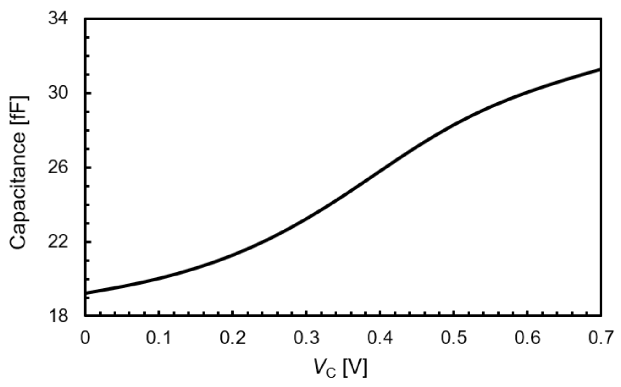
that is required to achieve fine tuning within the coarse-tuning segments. Specifically, the maximum variation of the varactor capacitance within the comparator hysteresis window was set 10% larger than CU to compensate for process tolerances and temperature variations. For the sake of completeness, the simulated varactor response as a function of the control voltage is shown in Figure 4.
The tuning circuit works as follows. As soon as control voltage VC reaches the value of threshold voltage VTk,H, the k-th comparator switches high, and a further unit capacitor is placed in parallel to the varactor, thus increasing the overall tank capacitor. After comparator switching, control voltage VC will increase toward VTk+1,H or will decrease toward VTk,L, depending on the PLL output frequency, fO. Specifically, if fO after switching is, for instance, higher than the value imposed by the PLL reference and divider, VC will go higher than VTk,H, and if it reaches VTk+1,H a further unit capacitor will be added in parallel to the varactor. If instead after switching of the k-th comparator fO is close to its steady-state value, this means that VTk,H is the coarse conversion of VC, which will settle around VTk,H according to the condition
V T k , L < V C < V T k + 1 , H  
thanks to the varactor that performs the fine frequency tuning. It is worth mentioning that the comparator hysteresis along with the condition in (1) are key concepts for the stability in this tuning strategy. Without hysteresis, control voltage VC and hence the PLL output frequency would oscillate around the steady-state value defined by the coarse conversion. Actually, hysteresis enables the flash A/D converter and allows fast, discrete coarse conversion and continuous fine conversion to be simultaneously achieved without any additional delay.

3. Experimental Results

The VCO was fabricated in a 28 nm FD-SOI CMOS technology by STMicroelectronics, which provides a very fast active device with fT and fMAX up to 300 GHz [23] and a standard back end of line (BEOL). The die microphotograph is shown in Figure 5. The VCO core silicon area is 210 µm × 150 µm.
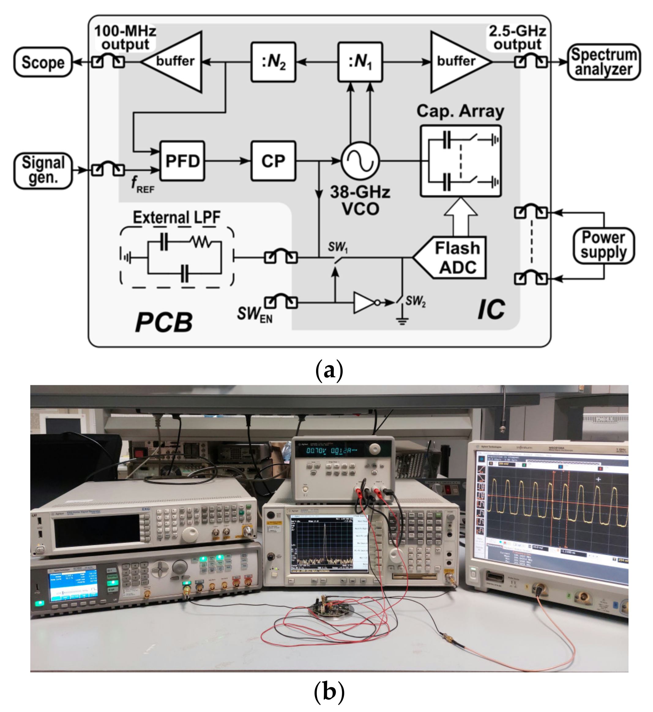
A block diagram and a photograph of the adopted measurement setup are shown in Figure 6a,b, respectively. The VCO was embedded within an on-chip PLL designed for testing purposes, which uses an off-chip second-order low-pass filter (LPF). Integrated switches SW1 and SW2 were externally driven to enable/disable the SC array. The integrated PLL exploits a frequency divider, N, by 384, which leads to a reference frequency of around 100 MHz. The measurement setup includes a spectrum analyzer and a digital oscilloscope for spectrum and transient measurements, respectively. A signal generator was also used to generate the PLL reference signal. Measurements were performed at 0.7-V power supply.
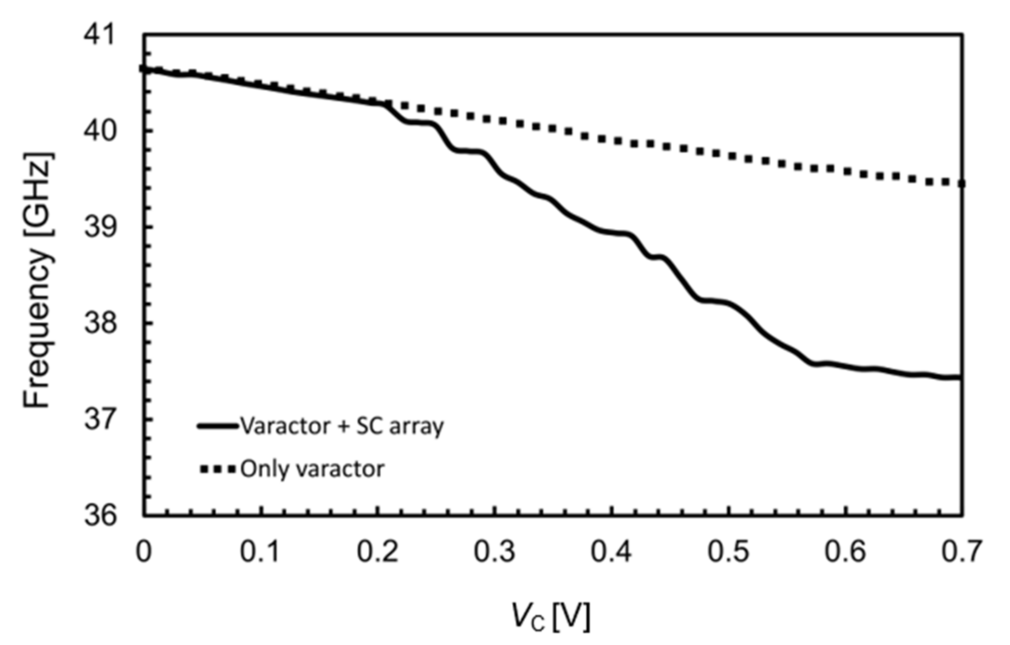
Figure 7 depicts the measured VCO tuning range. The oscillation frequency ranges from 37.4 to 40.7 GHz when varactor control voltage VC sweeps from 0 to 0.7 V. For the sake of completeness, the tuning range provided by the varactor (i.e., with the tuning array disabled) is also reported. The VCO tuning curve is set by the varactor as long as the capacitor array is not operated. This is true for a control voltage that is lower than the high threshold voltage, VT1,H, of the first comparator, which was set to about 220 mV. Indeed, Figure 7 shows that for low control voltages the overall tuning curve and the varactor tuning curve are overlapped. Once the control voltage overcomes VT1,H, the first switched capacitor is inserted, and fine and coarse tuning are simultaneously performed. As is apparent, the varactor performs a small fraction of the overall tuning range, which instead is mainly provided by the SC array.
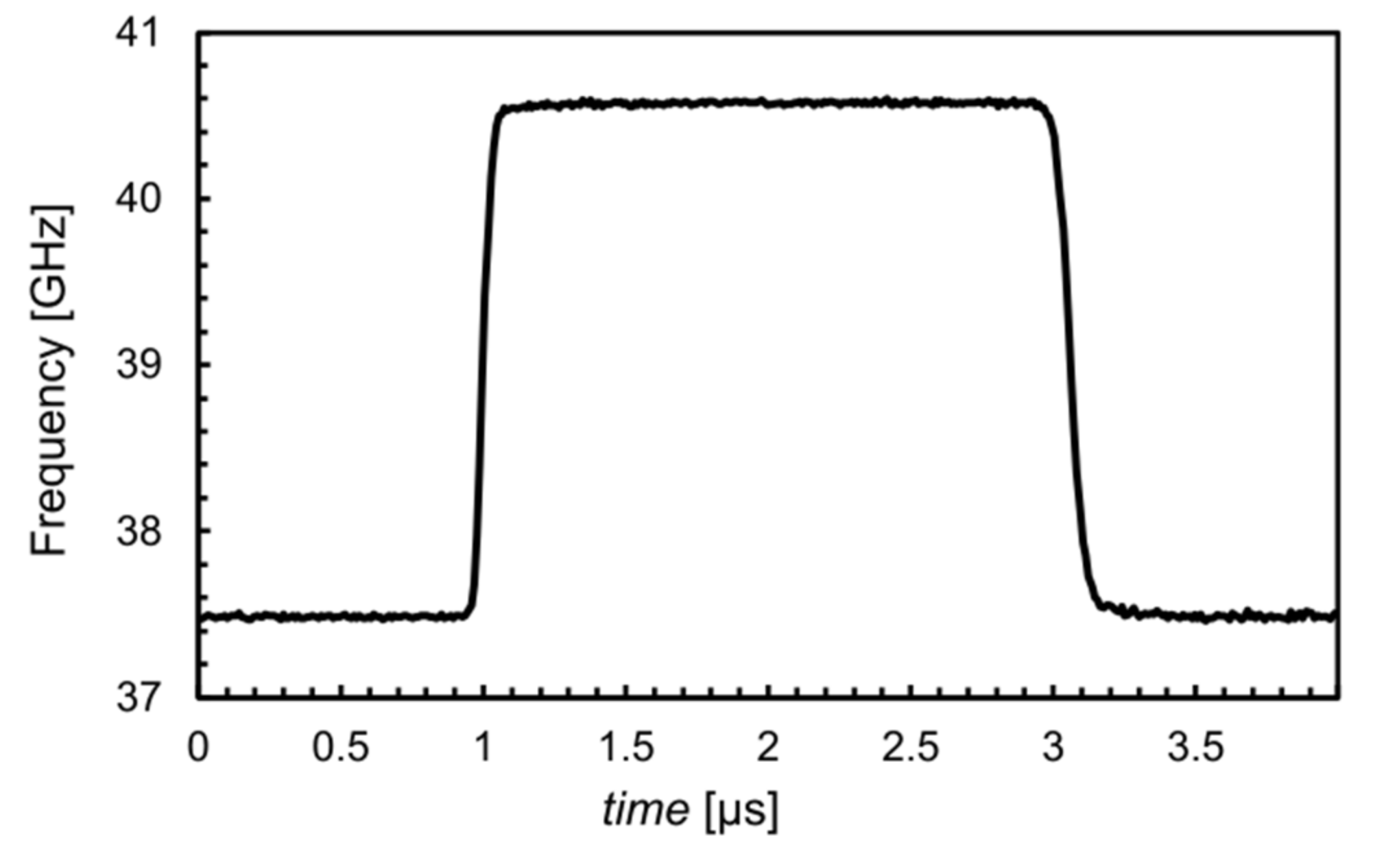
Figure 8 shows the VCO frequency transient response. The PLL bandwidth was set to 5 MHz, and a frequency step from 97.6 MHz to 105.6 MHz was applied to the PLL frequency reference. Under these conditions, the VCO frequency settles in about 0.2 µs, which is the overall PLL locking time including both array and varactor operations. For the sake of clarity, the response to a frequency step was carried out setting the PLL bandwidth to a low value (i.e., 20 kHz) to better show the staircase frequency transient response due to the switched capacitor array. Figure 9 displays the VCO output frequency, fVCO, the input frequency step, fREF, normalized to fVCO (i.e., fREF × N), and the control voltage, VC. As is apparent, the transient response is mainly set by the slew rate due to the high dominant-pole capacitor in the loop filter. Note that the slope in each step is the effect of the varactor on the frequency variation within the hysteresis window. It demonstrates that coarse and fine tuning can be operated at the same time without any delay.
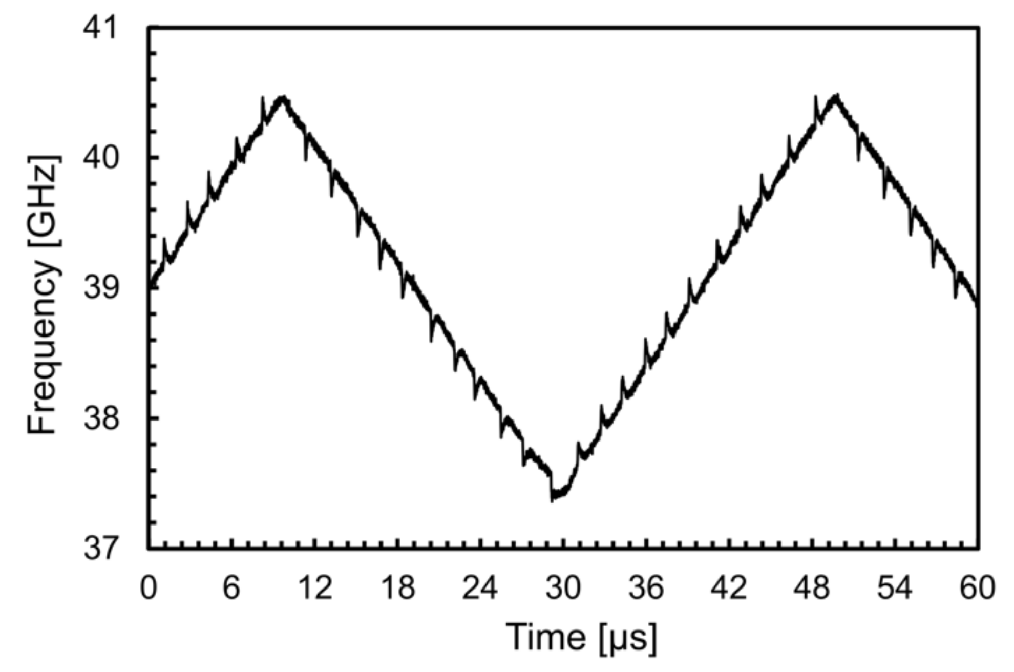
Figure 10 depicts the measured PLL output frequency for a frequency-modulated reference signal with a triangular shape. Specifically, a period of 40 μs and a 3-GHz frequency variation was set. As is apparent, continuous-time operation with variable PLL reference frequency is possible. Such a dynamic response is enabled by the proposed tuning strategy, which avoids any tuning delay.
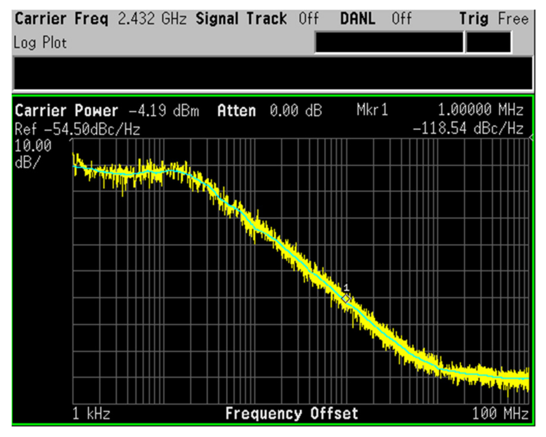
For the sake of completeness, the phase noise of the VCO was also measured by setting the PLL bandwidth as low as 20 kHz to make the VCO noise contribution dominant at the PLL output. The measurement was carried out by taking the noise at the 2.5-GHz output of the loop divider. This noise was about −118 dBc/Hz at 1-MHz offset frequency, as shown in Figure 11. The phase noise evaluated at 39 GHz was about equal to −94 dBc/Hz.
The overall measured performance is summarized and compared with recent state-of-the-art mm wave CMOS VCOs in Table 1. The proposed solution does not suffer from the additional delay of conventional coarse-tuning techniques based on SC arrays. Moreover, the VCO exhibits a phase noise and tuning range that are similar to state-of-the-art, SC-based VCOs, despite a lower power supply.

4. Conclusions

A novel frequency tuning strategy for switched-capacitor-based mm wave VCOs has been presented, which overcomes the settling-time limitations of conventional SC tuning techniques. Indeed, by exploiting a customized flash A/D control circuit, coarse and fine tuning are simultaneously performed, thus getting rid of VCO calibration extra time. Thanks to the effectiveness of the proposed technique, high-speed frequency locking can be performed, which is usually required in advanced wireless communication systems.

Author Contributions

Conceptualization, A.P. and G.P. (Giuseppe Palmisano); methodology, A.P. and G.P. (Giuseppe Palmisano); validation, A.C., A.F. and G.P. (Giuseppe Papotto); formal analysis, A.P. and G.P. (Giuseppe Palmisano); investigation, A.P.; writing—original draft preparation, A.P., A.C. and G.P. (Giuseppe Papotto; writing—review and editing, A.P. and G.P. (Giuseppe Papotto); supervision, G.P. (Giuseppe Palmisano); project administration, G.P. (Giuseppe Palmisano) All authors have read and agreed to the published version of the manuscript.

Funding

This research received no external funding.

Acknowledgments

Special thanks to A. Castorina, STMicroelectronics, Catania, for measurement assistance.

Conflicts of Interest

The authors declare no conflict of interest.

References

  1. Arbabian, A.; Callender, S.; Kang, S.; Rangwala, M.; Niknejad, A.M. A 94 GHz mm-Wave-to-Baseband Pulsed-Radar Transceiver with Applications in Imaging and Gesture Recognition. IEEE J. Solid State Circuits 2013, 48, 1055–1071. [Google Scholar] [CrossRef]
  2. Shirazi, A.H.M.; Nikpaik, A.; Molavi, R.; Lightbody, S.; Djahanshahi, H.; Taghivand, M.; Mirabbasi, S.; Shekhar, S. On the Design of mm-Wave Self-Mixing-VCO Architecture for High Tuning-Range and Low Phase Noise. IEEE J. Solid State Circuits 2016, 51, 1210–1222. [Google Scholar] [CrossRef]
  3. Di Meo, S.; Svelto, F.; Summers, P.E.; Renne, G.; Preda, L.; Bellomi, M.; Espin-Lopez, P.F.; Martellosio, A.; Pasian, M.; Matrone, G.; et al. On the Feasibility of Breast Cancer Imaging Systems at Millimeter-Waves Frequencies. IEEE Trans. Microw. Theory Tech. 2017, 65, 1795–1806. [Google Scholar] [CrossRef]
  4. Maltsev, A.; Maslennikov, R.; Sevastyanov, A.; Khoryaev, A.; Lomayev, A. Experimental investigations of 60 GHz WLAN systems in office environment. IEEE J. Sel. Areas Commun. 2009, 27, 1488–1499. [Google Scholar] [CrossRef]
  5. Rajagopal, S.; Abu-Surra, S.; Ramakrishna, S.; Taori, R. MIMO designs for mmWave wireless LAN systems. In Proceedings of the 48th Asilomar Conference on Signals, Systems and Computers, Pacific Grove, CA, USA, 2–5 November 2014; pp. 1916–1920. [Google Scholar]
  6. Rakesh, R.T.; Sen, D.; Das, G.; Viterbo, E.; Hong, Y. On Distance Statistics of First Arriving Multi-Paths in Indoor mm-Wave Communications. IEEE Trans. Veh. Technol. 2020, 69, 16218–16223. [Google Scholar]
  7. Fettweis, G.; Alamouti, S.M. 5G: Personal mobile internet beyond what cellular did to telephony. IEEE Commun. Mag. 2014, 52, 140–145. [Google Scholar] [CrossRef]
  8. Ek, S.; Påahlsson, T.; Elgaard, C.; Carlsson, A.; Axholt, A.; Stenman, A.-K.; Sundstrom, L.; Sjoland, H. A 28-nm FD-SOI 115-fs Jitter PLL-Based LO System for 24–30-GHz Sliding-IF 5G Transceivers. IEEE J. Solid State Circuits 2018, 53, 1988–2000. [Google Scholar] [CrossRef]
  9. Cavarra, A.; Papotto, G.; Parisi, A.; Finocchiaro, A.; Nocera, C.; Palmisano, G. Transformer-Based VCO for W-Band Automotive Radar Applications. Electronics 2021, 10, 531. [Google Scholar] [CrossRef]
  10. Lee, J.; Li, Y.-A.; Hung, M.-H.; Huang, S.-J. A Fully-Integrated 77-GHz FMCW Radar Transceiver in 65-nm CMOS Technology. IEEE J. Solid State Circuits 2010, 45, 2746–2756. [Google Scholar]
  11. Papotto, G.; Nocera, C.; Finocchiaro, A.; Parisi, A.; Cavarra, A.; Castorina, A.; Ragonese, E.; Palmisano, G. A 27-mW W-Band Radar Receiver With Effective TX Leakage Suppression in 28-nm FD-SOI CMOS. IEEE Trans. Microw. Theory Tech. 2021, 69, 4132–4141. [Google Scholar] [CrossRef]
  12. Vovnoboy, J.; Levinger, R.; Mazor, N.; Elad, D. A Dual-Loop Synthesizer with Fast Frequency Modulation Ability for 77/79 GHz FMCW Automotive Radar Applications. IEEE J. Solid State Circuits 2018, 53, 1328–1337. [Google Scholar] [CrossRef]
  13. Ma, T.; Deng, W.; Chen, Z.; Wu, J.; Zheng, W.; Wang, S.; Qi, N.; Liu, Y.; Chi, B. A CMOS 76–81-GHz 2-TX 3-RX FMCW radar transceiver based on mixed-mode PLL chirp generator. IEEE J. Solid State Circuits 2019, 55, 233–248. [Google Scholar] [CrossRef]
  14. Qiao, J.; Shen, X.S.; Mark, J.W.; Lei, L. Video Quality Provisioning for Millimeter Wave 5G Cellular Networks with Link Outage. IEEE Trans. Wirel. Commun. 2015, 14, 5692–5703. [Google Scholar] [CrossRef]
  15. Abdulaziz, M.; Forsberg, T.; Tormanen, M.; Sjoland, H. A 10-mW mm-Wave Phase-Locked Loop with Improved Lock Time in 28-nm FD-SOI CMOS. IEEE Trans. Microw. Theory Tech. 2019, 67, 1588–1600. [Google Scholar] [CrossRef] [Green Version]
  16. Lin, T.-H.; Kaiser, W.J. A 900-MHz 2.5-mA CMOS frequency synthesizer with an automatic SC tuning loop. IEEE J. Solid State Circuits 2001, 36, 424–431. [Google Scholar]
  17. Lin, T.-H.; Lai, Y.-J. An Agile VCO Frequency Calibration Technique for a 10-GHz CMOS PLL. IEEE J. Solid State Circuits 2007, 42, 340–349. [Google Scholar] [CrossRef] [Green Version]
  18. Shin, J.; Shin, H. A Fast and High-Precision VCO Frequency Calibration Technique for Wideband ΔΣ Fractional-N Frequency Synthesizers. IEEE Trans. Circuits Syst. I Regul. Pap. 2009, 57, 1573–1582. [Google Scholar] [CrossRef]
  19. Ryu, H.; Sung, E.-T.; Park, S.; Cho, J.-K.; Baek, D. Fast Automatic Frequency Calibrator Using an Adaptive Frequency Search Algorithm. IEEE Trans. Very Large Scale Integr. Syst. 2016, 25, 1490–1496. [Google Scholar] [CrossRef]
  20. Ferriss, M.; Sadhu, B.; Rylyakov, A.; Ainspan, H.; Friedman, D. A 12-to-26GHz fractional-N PLL with dual continuous tuning LC-D/VCOs. In Proceedings of the IEEE International Solid-State Circuits Conference (ISSCC), San Francisco, CA, USA, 31 January–4 February 2016; pp. 196–198. [Google Scholar]
  21. Shi, C.; Yang, H.; Xiao, H.; Liu, J.; Liao, H. A dual loop dual VCO CMOS PLL using a novel coarse tuning technique for DTV. In Proceedings of the 9th International Conference on Solid-State and Integrated-Circuit Technology, Beijing, China, 20–23 October 2008; pp. 1597–1600. [Google Scholar]
  22. Parisi, A.; Finocchiaro, A.; Cavarra, A.; Papotto, G.; Palmisano, G. An Oscillator Circuit, Corresponding Radar Sensor, Vehicle and Method of Operation. Italy Patent Application 102020000019786, 7 August 2020. [Google Scholar]
  23. Cathelin, A. Fully depleted silicon on insulator devices CMOS: The 28 nm node is the perfect technology for analog, RF, mmW, and mixed signal system-on-chip integration. IEEE Solid State Circuits Mag. 2017, 9, 18–26. [Google Scholar] [CrossRef]
  24. Deng, W.; Song, Z.; Ma, R.; Lin, J.; Li, Y.; Ye, J.; Kong, S.; Hu, S.; Jia, H.; Chi, B. An Energy-Efficient 10-Gb/s CMOS Millimeter-Wave Transceiver with Direct-Modulation Digital Transmitter and I/Q Phase-Coupled Frequency Synthesizer. IEEE J. Solid State Circuits 2020, 55, 2027–2042. [Google Scholar] [CrossRef]
Figure 1. Typical transient response of an SC-based PLL.
Electronics 11 00433 g001
Figure 2. Voltage-controlled oscillator: (a) schematic, (b) 3-D view of transformer T1 with the adopted metal stack and its main parameters.
Electronics 11 00433 g002
Figure 3. Simplified schematic of the proposed tuning circuit.
Electronics 11 00433 g003
Figure 4. Simulated varactor response as a function of the control voltage.
Electronics 11 00433 g004
Figure 5. Die microphotograph.
Electronics 11 00433 g005
Figure 6. Adopted measurement setup: (a) block diagram, (b) photograph.
Electronics 11 00433 g006
Figure 7. Measured tuning range.
Electronics 11 00433 g007
Figure 8. Transient response of the VCO oscillation frequency with 5-MHz PLL bandwidth.
Electronics 11 00433 g008
Figure 9. Transient response of the VCO oscillation frequency with 20-kHz PLL bandwidth.
Electronics 11 00433 g009
Figure 10. Measured dynamic frequency locking with a triangular reference frequency.
Electronics 11 00433 g010
Figure 11. Measured phase noise at 2.5-GHz carrier frequency.
Electronics 11 00433 g011
Table 1. Performance summary and comparison with the state of the art.
Ek JSSC’18
[8]
Ma JSSC’20
[13]
Deng JSSC’20
[24]
This
Work
CMOS technology28 nm FD-SOI65 nm65 nm28 nm FD-SOI
Power supply(V)1.2110.7
Power consumption(mW)3.3-11.68.4
Tuning approach SC + varactorSC + varactorSC + VaractorSC + varactor
Center frequency(GHz)1839.62039
Tuning range(GHz)16.3 to 19.737.2 to 4217.4 to 22.437.4 to 40.7
PN(a) @ 1 MHz(dBc/Hz)−92.3 (b)−93.4−96.9−94
Calibration extra time YESYESYESNO
(a) Normalized around 39 GHz. (b) Simulated.
Publisher’s Note: MDPI stays neutral with regard to jurisdictional claims in published maps and institutional affiliations.