Abstract
Medium access control (MAC) protocol operations for in-band full duplex multi-hop networks play an important role in efficient data relaying and throughput enhancement. Knowledge of the relationship between essential operations in MAC protocol for full duplex MAC (FD MAC) networks and network performance is important and useful in terms of the protocol and network design. FD MAC protocols often require exchanging control frames, e.g., request to send/clear to send (RTS/CTS). However, the conventional model cannot analyze the performance of wireless multi-hop networks with RTS/CTS-based FD MAC. Thus, this paper proposes a throughput analysis model for wireless multi-hop networks with RTS/CTS-based FD MAC. The proposed model includes novel “airtime expressions”, which allows us to handle RTS/CTS operations under FD MAC. The proposed model provides the end-to-end throughput of multi-hop networks with RTS/CTS-based FD MAC for any number of hops and any payload size. The validity of the analytical expressions is confirmed through comparisons with simulation results.
1. Introduction
Recently, the wireless full-duplex (FD) communication technique has attracted research attention. In wireless multi-hop networks, wireless FD communication allows relay nodes to transmit and receive data signals simultaneously in the same frequency band. This technique provides efficient data relaying and mitigation of data-transmission collisions induced by hidden nodes [1,2,3,4]. Because FD communication may become a powerful solution in terms of improving multi-hop network performance; thus, many studies into wireless FD multi-hop networks have been conducted, particularly in the last decade [1,2,3].
The operation of medium access control (MAC) protocols for full duplex MAC (FD MAC) networks play an important role in efficient data relay and improving throughput. MAC protocols for distributed networks, e.g., multi-hop networks and wireless local area network (WLAN), have been designed based on carrier-sense multiple access with collision avoidance (CSMA/CA). Two main types of CSMA-based FD MAC have been proposed; header snooping-based FD MAC [4,5,6,7,8] and request to send/clear to send (RTS/CTS)-based FD MAC [9,10,11,12,13,14,15,16]. The difference between the two schemes is whether or not network nodes exchange control frames prior to a DATA-frame transmission with FD communication. From a MAC protocol design perspective, knowledge of the relationship between essential operations in each FD MAC and network performance is important and useful.
In terms of the above motivation, some studies have focused on theoretical analysis of wireless FD multi-hop networks. Throughput analysis for CSMA/CA-based FD multi-hop networks has been proposed previously [17]; however, the model [17] cannot analyze the performance of wireless FD multi-hop networks with RTS/CTS-based FD MAC. In a simple multi-hop network, e.g., a string-topology, the header snooping-based FD MAC may provide higher throughput than RTS/CTS-based FD MAC due to its overheads for FD data transmissions. However, in real-world ad hoc network systems, the network topology or wireless link quality frequently varies due to node mobility, channel fading, and interference. To adapt to such situations, some control frames must be exchanged among network nodes [18,19]. From the viewpoint of MAC-layer operations, it is helpful for clarifying the relationship between network performance and an essential operation in RTS-based FD MAC. Throughput analysis for IEEE 802.11 multi-hop networks with RTS/CTS has been proposed in [20]. However, the application range in this model is so limited that it is difficult to extend to the theoretical analysis model for the multi-hop network with FD MAC. Ref. [14] takes into account multi-hop networks with RTS/CTS-based FD MAC, and provides the performance analysis based on an analytical model. However, the essential behaviors in multi-hop networks, such as collisions induced by hidden nodes and NAV operation, have been not considered in the analytical model of [14]. Clarifying the relationship between the network performance and essential behavior of multi-hop networks under the use of RTS/CTS-based FD MAC theoretically is useful for the protocol design and the optimization. Therefore, the performance analysis and future protocol design for FD multi-hop networks require the establishment of an analytical model for multi-hop networks with RTS/CTS-based FD MAC.
This paper proposes a throughput analysis model for wireless multi-hop networks with RTS/CTS-based FD MAC. The purpose of this paper is to clarify the relationship between network performance and an essential operation in RTS-based FD MAC. To develop the model, we also propose novel “airtime expressions”, which allows us to handle RTS/CTS operations under FD MAC. The proposed airtime expressions are effective for theoretical analysis of multi-hop networks [20,21,22,23,24], and the proposed model provides the end-to-end throughput of multi-hop networks with RTS/CTS-based FD MAC for any number of hops and any payload size. The validity of the analytical expressions is demonstrated through comparisons with simulation results. The proposed analytical model can be easily applied to performance analysis for half-duplex (HD) multi-hop networks with RTS/CTS. Therefore, the proposed model enables us to mathematically evaluate the performance of RTS/CTS multi-hop networks for FD and HD.
The rest of this paper is organized as follows. Section 2 provides an overview of related work, specifically wireless FD communication and CSMA-based FD MAC protocols, RTS/CTS-based FD MAC in multi-hop networks, and theoretical analysis of wireless multi-hop networks. Section 3 proposes throughput analysis for multi-hop networks with RTS/CTS-based FD MAC. In Section 4, we evaluate the verification of the proposed analytical model. Finally, Section 5 concludes the paper.
2. Related Work
2.1. Wireless FD Communication and CSMA-Based FD MAC Protocols
FD communication is a revolutionary communication technique that enables nodes to perform frame transmission and reception simultaneously on the same frequency channel. In HD communication, a primary transmission node initiates frame transmission, and the receiver decodes the signals from the primary transmitter. In contrast, with the FD communication, the primary receiver can initiate frame transmission while the primary transmitter transmits signals. In other words, the primary receiver functions as the secondary transmitter in FD communication [1,2,3].
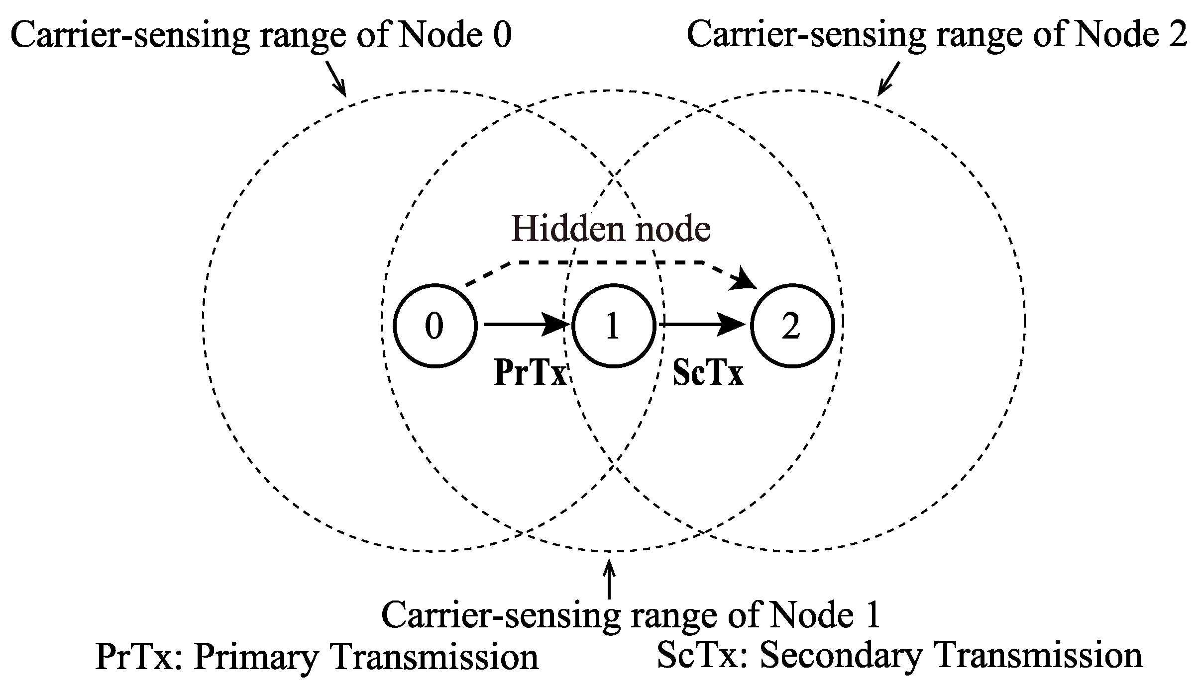
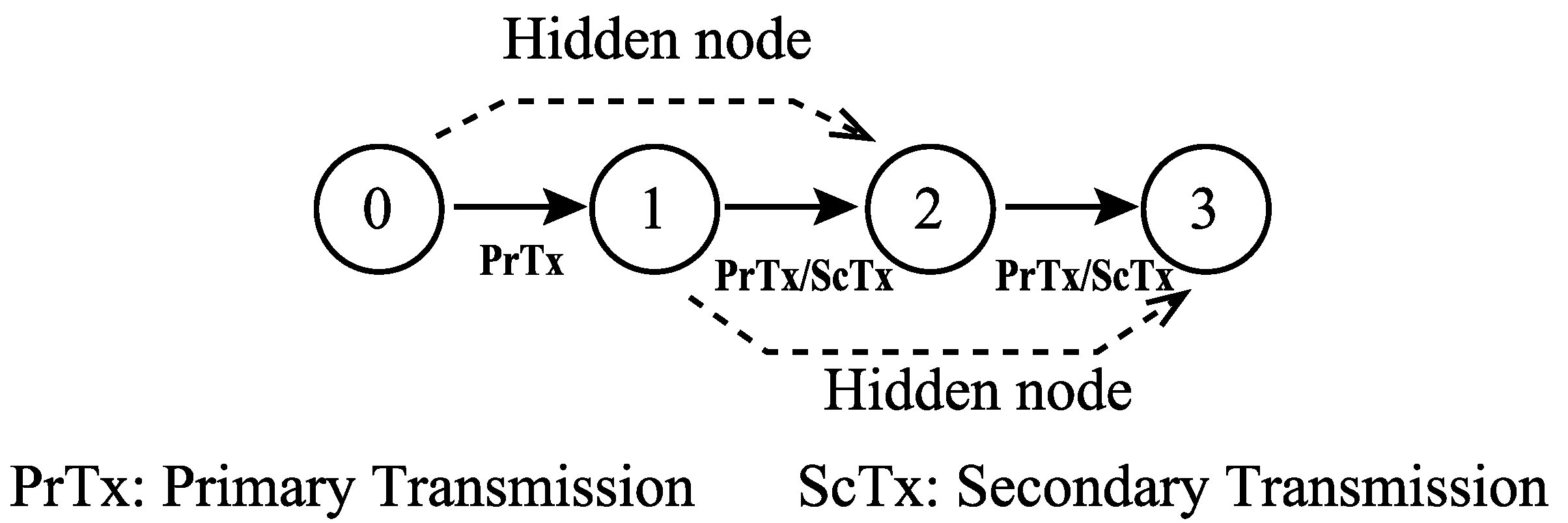
FD communication is categorized into two modes, i.e., bidirectional FD (BFD) and unidirectional FD (UFD) [1,2,3]. In the BFD mode, the two nodes involved in FD communication perform DATA-frame transmission and reception simultaneously. In the UFD mode, a single node performs DATA-frame transmission and reception. Figure 1 shows an example of UFD mode among three nodes, where, Nodes 0 and 1 are the primary transmitter and secondary transmitter (i.e., the primary receiver), respectively. In this example, Nodes 0 and 2 are in a hidden node relationship; therefore, frame transmissions from Node 2 may interfere with frame transmissions from Node 0 if Node 2 initiates the transmission of signals. This interference is referred to as “hidden node collision”. The secondary transmission in FD communication between Nodes 0 and 1 informs the hidden nodes about frame transmissions at Node 0. The secondary transmission prevents its neighboring nodes from initiation of transmission of any frame; thus, the primary transmission is protected in FD communication, which is one of the benefits of FD communication in networks.
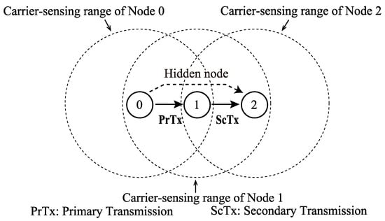
Figure 1.
Unidirectional FD communication.
Considering the uniqueness of FD communication, various MAC protocols for wireless FD networks have been proposed. Such protocols are classified into two main types, i.e., header snooping-based FD MAC [4,5,6,7,8] and RTS/CTS-based FD MAC [9,10,11,12,13,14,15,16]. The difference between the two schemes is whether or not the network nodes exchange control frames for DATA-frame transmission with FD. RTS/CTS handshaking also reduces hidden node collisions, however, its overheads for FD data transmissions may degrade throughput. In a simple multi-hop network, e.g., a string-topology, the header snooping-based FD MAC may provide higher throughput than RTS/CTS-based FD MAC because the header snooping-based FD MAC has lower overheads for FD transmissions. However, in real-world ad hoc network systems, it is assumed that the network topology or wireless link quality varies frequently due to node mobility, channel fading, and interference. Therefore, in order to adapt to such situations, it is essential to exchange some control frames among network nodes [18,19]. In this sense, RTS/CTS-based FD MAC design is an important task, especially for ad hoc networks. In addition, it is necessary to clarify the relationship between the essential operations of RTS/CTS-based FD MAC and network performance. The performance analysis and future protocol design for FD multi-hop networks require an analytical model for multi-hop networks with RTS/CTS-based FD MAC.
2.2. RTS/CTS-Based FD MAC in Multi-Hop Netw
Several RTS/CTS-based FD MAC protocols have been proposed in the last decade. To the best of our knowledge, ref. [9] was the first paper which proposes a fundamental RTS/CTS-based FD MAC. The fundamental operation in RTS/CTS-based FD MAC is three-way handshaking with control frames. The main purpose of such handshaking is to specify the secondary transmitter for FD communication. Several protocols [14,15,16] apply the three-way handshaking for the same purpose. Therefore, we introduce the fundamental operations of three-way handshaking of RTC/Full duplex CTS(FCTS) [9] in multi-hop networks.
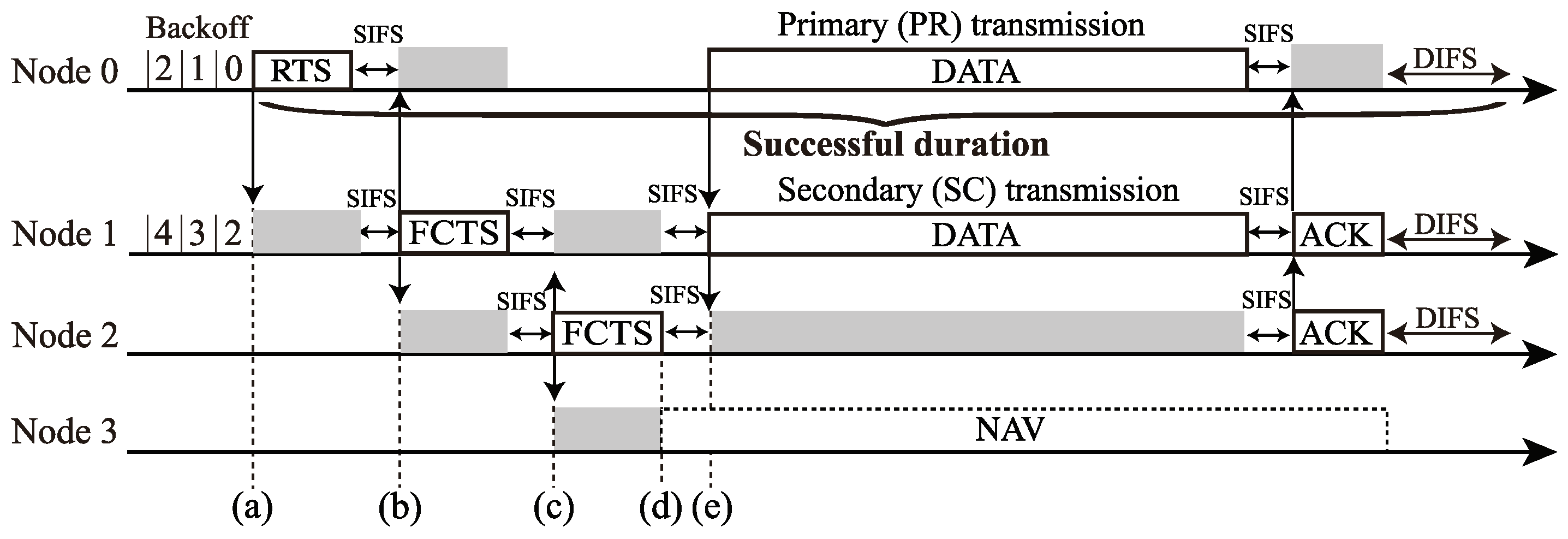
Figure 2 and Figure 3 show a three-hop network and a channel access example of the RTS/CTS-based FD MAC in the three-hop network, respectively. In Figure 2, Nodes 0(1) and 2(3) are in a hidden node relationship. Here, channel access is based on distributed coordination function (DCF) in IEEE 802.11. In the RTS/CTS-based FD MAC, each node exchanges some control frames, which are RTS and FD CTS (FCTS), before a DATA-frame transmission. Node 0 transmits an RTS frame to Node 1 when its backoff timer is zero (Figure 3a), and then Node 1 begins to transmit an FCTS frame to Node 2 after successfully receiving the RTS frame (Figure 3b). The purpose of the FCTS transmission is to inform Node 1’s neighboring nodes that Node 1 is going to initiate transmission of a DATA-frame. The FCTS transmission also functions to prevent the hidden nodes of Node 0 from transmitting frames. By receiving the FCTS frame from Node 1, Node 2 also sends an FCTS frame to Node 1 to inform its neighboring nodes that Node 2 will receive the DATA-frame as a secondary receiver (Figure 3c). Node 3 receives the FCTS frame from Node 2; thus, Node 3 sets the Network Allocation Vector (NAV), which forbids the nodes with it from transmitting frames (Figure 3d). After exchanging these control frames, Nodes 0 and 1 begin to transmit their DATA-frames through FD transmission (Figure 3e).

Figure 2.
A three-hop network.
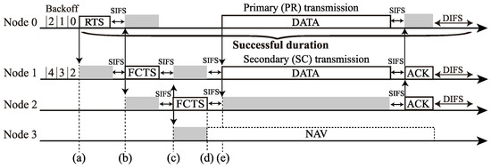
Figure 3.
Channel-access example. of the RTS/CTS-based FD MAC in the three-hop network (Figure 2): (a) Node 0’s RTS transmssion, (b) Node 1’s FCTS transmission, (c) Node 2’s FCTS transmission, (d) Node 3 setting NAV, and (e) Nodes 0 and 1 begin to transmit their DATA-frames through FD transmission.
If Node 2 fails to receive the FCTS frame at (b) in Figure 3, Node 2 does not return an FCTS frame, and only Node 0 transmits its DATA frame. If Node 1 has no DATA-frame when receiving the RTS frame from Node 0, Node 1 returns an FCTS frame to Node 0. Here, Node 2 sets NAV, and only the DATA from Node 0 is transmitted with HD communication, and this is a unique operation of FD multi-hop networks.
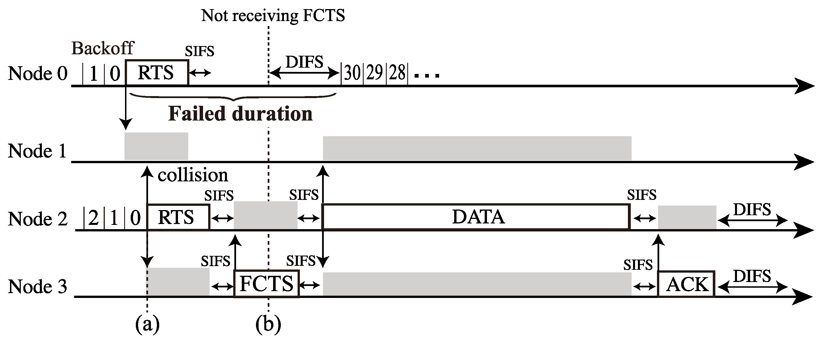
Figure 4 shows an example of channel access failure for the RTS/CTS-based FD MAC. In Figure 4a, the RTS frame transmission from Node 2 collides with that from Node 0 due to hidden node collisions. Therefore, Node 1 does not return an FCTS frame to Node 0. Then, Node 0 fails in its RTS transmission (Figure 4b).

Figure 4.
Channel-access failure example of the RTS/CTS-based FD MAC in the three-hop network (Figure 2): (a) a collisison bertween Node 0’s RTS transmiission and Node 1’s RTS one, and (b) Node 0 fails in its RTS transmission, then attmepts to retransmit the RTS.
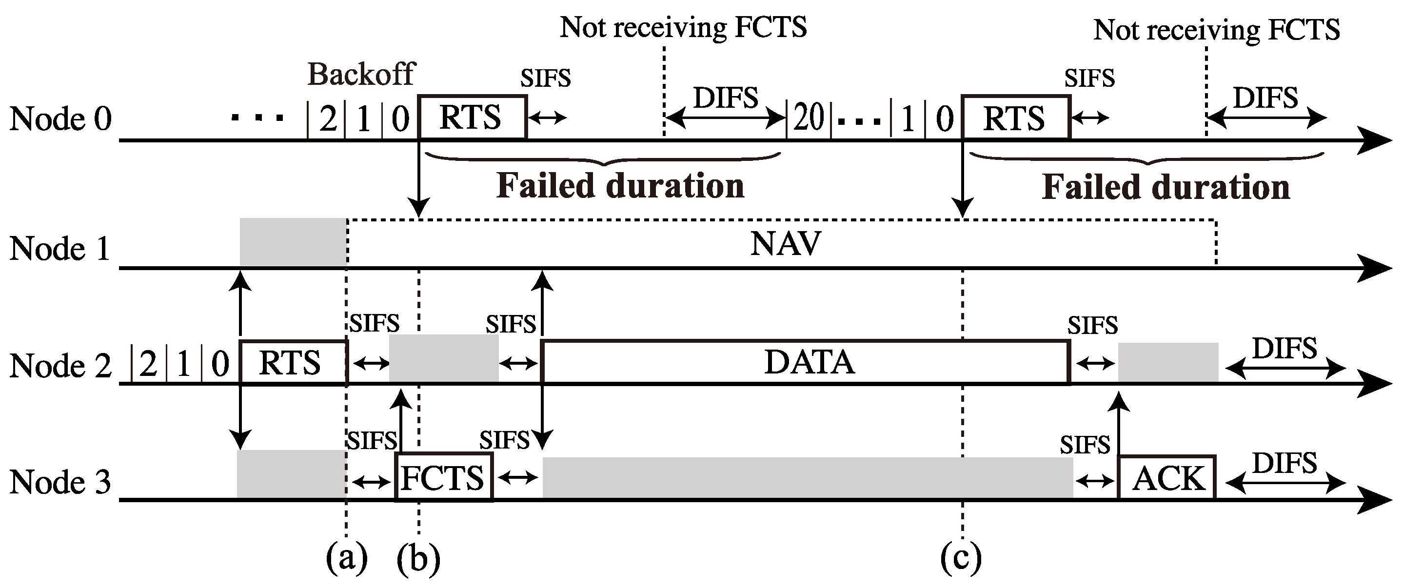
However, in the multi-hop networks with control frame exchanges, another transmission failure appears due to NAV operation, as shown in Figure 5. Here, Node 1 sets NAV after receiving the RTS frame from Node 2 (Figure 5a). Thus, Node 1 is permitted to transmit frames. However, Node 0 does not notice that Node 1 is under this constraint, i.e., the NAV setting. As a result, Node 0 attempts to transmit RTS frames repeatedly; however, Node 1 cannot reply to the RTSs (Figure 5b,c), which means that Node 0 cannot perform in RTS transmission successfully until the NAV duration expires at Node 1. Generally, RTS frames the mitigation of hidden node collisions; however, it may cause frame transmission failures with RTS frame reception under the NAV operation in multi-hop networks.
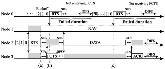
Figure 5.
Transmission failure caused by NAV operation in the three-hop networks (Figure 2): (a) Node 1 setting NAV, (b) Node 0’s RTS transmission failure, and (c) Node 0 attempts to transmit RTS frames repeatedly; however, Node 1 cannot reply to the RTSs due to the NAV.
2.3. Theoretical Analysis of Wireless Multi-Hop Networks Based on the Airtime-Expressions Approaches
The string topology network is one of the simple and fundamental multi-hop network topologies. The string topology multi-hop networks are considered in various applications, such as sensor networks [25], mesh networks [26,27], vehicular ad hoc networks [28], unmanned aerial vehicle networks [29], etc. It is not easy to comprehend the network dynamics of string-topology multi-hop networks. This is because network nodes interact with one another in spite of their individual operations. It can be stated that analytical expressions of string-topology multi-hop network performance are helpful and valuable. From these reasons, a string topology multi-hop network is often considered as the analysis subject in the researches for multi-hop networks [30].
A promising approach for developing an analytical model for multi-hop networks is airtime expressions [20,21,22,23,24]. In airtime expressions analysis, the airtime spent for Node i transmitting frames in a long time interval [0, ] is referred as transmission airtime, which is defined as follows:
where is the durations that are used by Node—i frame transmission. Here, has the same mean as the probability that Node i transmits frames within a long time interval [0, ] [21,22]. Generally, a multi-hop network covers a wide area where the source nodes cannot send packets directly to destination nodes. Therefore, each node is affected differently in the local environment, which means that each node has a different collision probability and carrier-sensing probability in multi-hop networks. With the airtime expressions for each node in the network, the theoretical throughput can be derived in consideration of the different characteristics of each node in multi-hop networks, and this is why the airtime expressions approach is effective for multi-hop network analysis.
In [21], the maximum throughput for a long hop network is derived based on the original airtime expressions. With the transmission airtime, the expression of the carrier-sensing probability for each node in the multi-hop network is proposed in [22]. By considering both the collision and carrier-sensing probabilities for each node, ref. [22] derived the maximum throughput for the networks with any hops. Ref. [23] extended the theoretical analysis under non-saturation condition by proposing the frame-existence probability. Ref. [24] integrated the airtime expressions analysis and Bianchi’s Markov-chain model [31] to express the relationship between the durations of backoff-timer decrements and those of frame transmissions. This model allows us to handle more detailed operations regarding the backoff operation in the DCF for each node in multi-hop networks.
In addition, an analytical model that employs airtime expressions analysis for FD multi-hop networks has been proposed in [17]. As mentioned previously, each node in an FD multi-hop network often performs HD transmissions; thus, the analytical model for FD multi-hop networks must consider the FD and HD operations for each node. In this model, the airtime expressions and Markov-chain model for the backoff operation in the FD MAC [4] are integrated. This integration allows us to divide transmission airtime into three parts, i.e., the primary (PR), secondary (SC) transmissions, and the HD transmissions. However, the exiting model [17] assumes multi-hop networks with the header snooping-based FD MAC; therefore, this model cannot analyze the performance of multi-hop networks with the RTS/CTS-based FD MAC.
Based on the airtime expression approach, throughput analysis for IEEE 802.11 multi-hop networks with RTS/CTS has been proposed previously [20], and this model was established by extending the concepts presented in [21]. Note that this model assumes a string topology long multi-hop network under the saturated condition. Therefore, the application range of the [20] is limited. Ref. [14] takes into account multi-hop networks with RTS/CTS-based FD MAC, and provides the performance analysis based on an analytical model. Because the model is specified for the evaluations of the performance proposed in [14], extending the model to a general analytical model, which takes into account the essential behaviors in multi-hop networks, such as collisions induced by hidden nodes and NAV operation, under the use of RTS/CTS-based FD MAC. Establishing an analytical model for RTS/CTS-based multi-hop networks with an unlimited application range has been challenging due to the complex behaviors of RTS/CTS operations in multi-hop networks. Therefore, to the best of our knowledge, the extended analytical model for multi-hop networks with RTS/CTS has not been proposed to date.
3. Proposed Throughput Analysis for Multi-Hop Networks with RTS/CTS-Based FD MAC
This section proposes a throughput analysis method for multi-hop networks with RTS/CTS-based FD MAC. Here, we assume a string-topology H-hop network (Figure 6) as the network model [17,20,21,22,23,24]. From the viewpoint of MAC layer operations, the analysis focuses on clarifying the relationship between network performance and an essential operation in RTS-based FD MAC; therefore, the analysis is based on the following assumptions.

Figure 6.
H-hop string-topology network.
- Only Node 0 generates fixed-sized user datagram protocol (UDP) DATA-frames, whose payload size is P [bytes]. The DATA-frame generation follows Poisson arrival process. The destination of all DATA-frames is Node H.
- Node i, for i = 1, 2, ⋯, 1, only relays the DATA-frames received from Node 1. Relay nodes never generate DATA-frames by themselves.
- The channel conditions are ideal without errors in the PHY layer; therefore, transmission failures occur due to frame transmission collisions in the MAC layer.
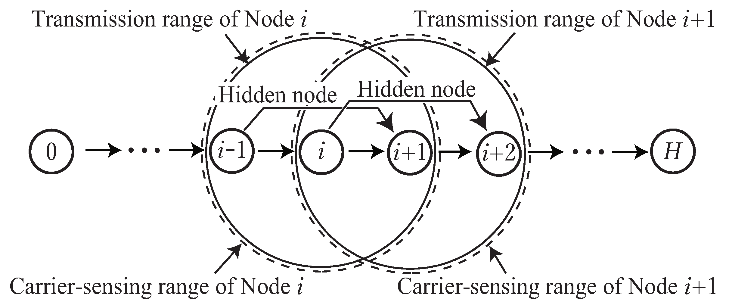
- The transmission from each node reaches its neighboring nodes in a single hop. In other words, Nodes 1 and 1 are within the transmission range of Node i (Figure 6) [32,33].
- The carrier-sensing range for each node is the same as its transmission range; therefore, Nodes i and 2 form a hidden node relationship [17,20].
3.1. Airtime Expressions
In this analysis, we first derive the expressions of transmission airtime consideration of the RTS/CTS operations. In Figure 3 and Figure 4, the successful and failed durations for frame transmissions are shown as “Successful duration” and “Failed duration”, respectively. In the RTS/CTS-based FD MAC, the successful duration differs from the failed duration due to the exchange of control frames. Note that this difference is not considered in the conventional definition of transmission airtime (Equation (1)); thus, developing an analytical model for RTS/CTS-based FD MACs requires airtime expressions that consider the difference between successful and failed durations.
First, the successful and failed durations of Node i are defined as and , respectively. Using transmission failure probability for Node i, the average number of transmission attempts for Node i is expressed as follows:
where m is the retransmission limit. In other words, 1 is the average number of retransmissions for Node i. Therefore, the average transmission duration for a DATA frame is expressed as . Here, the transmission airtime for Node i is the probability that Node i is in the transmission state. is obtained as the product of frame arrival rate for Node i and the average transmission duration for a DATA–frame as follows:
To express the FD MAC operation in multi-hop networks, we obtain the expressions of transmission airtimes for HD, PR, and SC cases. Here, the ratio of the number of HD transmissions to the total number of transmissions with respect to Node i is defined as . Similarly, the ratio of the number of PR (SC) transmissions to the total number of transmissions with respect to Node i is defined as (), and these satisfy . Note that the successful (failed) duration for each transmission is different (Table 1). In Table 1, express the successful (failed) duration for HD transmissions, and these durations for PR and SC transmissions are expressed as similar to and , respectively. In Table 1, and represent the duration for distributed interframe space and short interframe space, respectively. In addition, , , , , and in Table 1 represent the duration for the header part of the DATA–, RTS–, FCTS–, DATA–, and ACK–frame transmissions, respectively.

Table 1.
Successful and failed durations for HD–, PR–, and SC–transmission cases.
Following Equation (3), the transmission airtimes for the HD, PR, and SC transmissions for Node i are expressed as
respectively. Note that HD, PR, and SC transmissions are disjoint; thus the transmission airtime for Node i is expressed as the sum of the transmission airtime for each case:
As shown in Equation (6), is the mean value of , , and , which is similar to .
By changing the parameter setting as , the proposed analysis can be easily applied to analysis for FD multi-hop networks without RTS/CTS-based FD MAC [17]. This means the proposed model includes all the results of [17].
3.2. Derivations of , , and
Here, we derive , , and . In the FD multi-hop network, SC transmissions are triggered by PR transmissions; thus, the node begins SC transmissions even if their backoff timer is not zero. In contrast, nodes start PR transmissions when their backoff timer reaches zero. If the receiver of the PR transmission has no DATA-frame, the PR transmitter transmits its frame with HD communication. Here, the ratio of the number of HD and PR transmissions to the number of total number of transmissions for Node i is defined as . Then, , , and satisfy as follows:
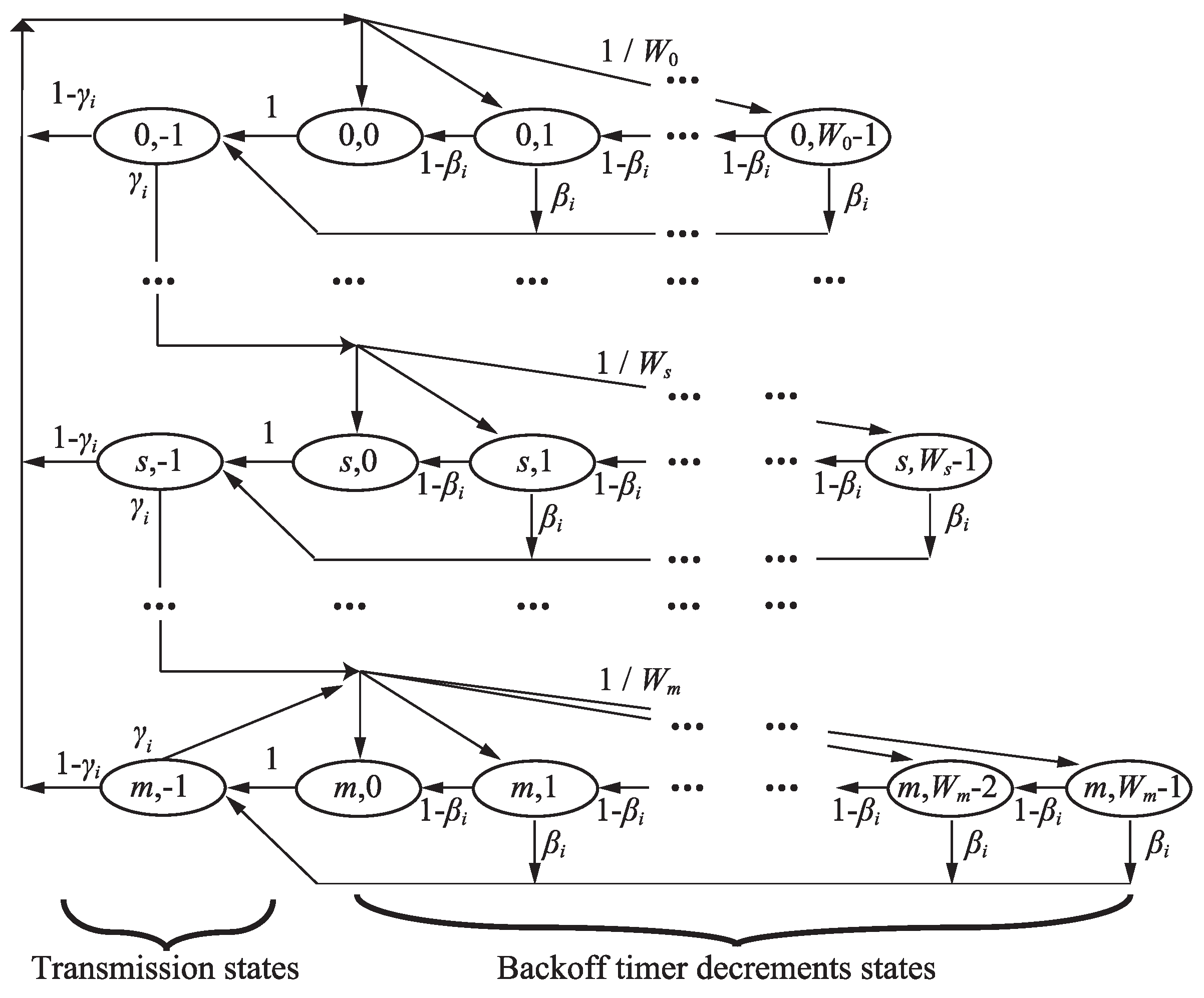
From the definition, can be expressed as the ratio of the number of transmissions with the backoff timer of zero to the total number of transmissions for Node i. Therefore, we derive the ratio from the Markov-chain model consideration of the FD MAC operations, as shown in Figure 7. In the Markov-chain model, state shows that Node i stays at the sth backoff stage with its backoff timer of k. The state for , belongs to “backoff timer decrement states” and the state for belongs to “transmission states”. Note that the transmission states shown in Figure 7 include HD, PR and SC cases. The value of the contention window of s–th backoff stage is , where is the value of CWmin. Nodes begin to perform the SC transmission even if their backoff timer is not zero. Using the SC transmission probability for Node i, in Figure 7, the transition probability regarding the SC transmissions is expressed as follows:

Figure 7.
Markov–chain model for FD MAC with respect to Node i.
In addition, the transition probabilities regarding backoff timer decrement and binary exponential backoff in DCF, are expressed as follows:
Here, we define the stationary distribution for each state in the Markov-chain model as . From Equations (8) and (9), we obtain the following relation regarding as follows:
where
In the Markov-chain model, all arrows with the probability of from the state (1,) flow into the state (1) through the backoff timer decrement states. Thus, we obtain the relationships between and as follows:
The sum of the stationary distributions is one. From Equations (10) and (12), we thus obtain the following:
From Equation (13), we obtain
By substituting Equations (11) and (14) into Equations (10) and (12), the stationary distribution of the state for , is expressed as a function of the transmission failure probability and the SC transmission probability.
In this model, the state for means that backoff timer of Node i is zero at each backoff stage. Therefore, the ratio of the number of transmissions with the backoff timer of zero to the total number of transmissions can be obtained as the ratio of the sum of the stationary distributions of the states with the backoff timer of zero for to the sum of the stationary distributions of the transmission state for , which is expressed as:
From Equations (7) and (15), the ratio of the number of SC transmissions to the total number of transmissions for Node i is obtained as a function of the transmission failure probability and SC transmission probability as follows:
Here, we define the ratio of the number of the HD transmissions to the sum of the numbers of HD and PR transmissions for Node i as . From the definition, , , and satisfy the following:
From the characteristics of FD multi-hop networks as shown in Figure 3, the number of the successful PR transmissions for Node i equals that of the SC transmission attempts for Node [17]. Therefore, using , we obtain the following relationship:
From Equation (18), we obtain the expression of as follows;
3.3. Carrier-Sensing Airtime:
Carrier-sensing airtime means the probability that the node detects channel busy. The carrier-sensing airtime for a given node in the FD MAC can be expressed as the sum of the transmission airtimes for its neighboring nodes [17,20,21,22,23,24]. Therefore, in the string-topology multi-hop network considered in this paper, the fundamental expression of carrier-sensing airtime for Node i can be obtained as the sum of the transmission airtimes for Nodes 1 and 1. However, we must consider the duplicated transmission duration between Nodes 1 and . In addition, we must consider the holding duration due to the NAV setting for the transmissions from Nodes 2 and . Thus, the proposed analysis includes the NAV duration in a carrier-sensing airtime.
To express the carrier-sensing airtime for Node i, it is divided into two parts. The first part, which is defined as , is the carrier-sensing airtime caused by transmissions from Nodes 1 and 1. The second party, which is defined as , is the carrier-sensing airtime from the NAV setting to protect the DATA-frame transmissions from Node 2. We derive and for each FD MAC.
In the FD MAC, we must consider the transmission duration from Nodes 1 and , as well as the NAV duration set by the transmissions from Node . As explained in Section 2.2, when Node i receives the RTS frame from Node , Node i is prohibited transmitting its frame due to the NAV setting until Node successfully completes the DATA-frame transmission. Note that the holding duration at Node i due to the NAV setting is updated when Node retransmits the RTS frame. In this sense, the holding duration due to the NAV setting is the sum of the duration of transmissions from Node and the holding duration due to the updating of the NAV setting. The holding duration at Node i due to the updating the NAV setting has the same length as the duration from the failed RTS transmission to RTS retransmission from Node ; thus, its duration is approximately the same length as that of the sum of the durations for the backoff timer decrements for the retransmissions from Node . Here, we define the average number of backoff timer decrements for a single successful DATA-frame transmission from Node i as . can be obtained as the expected recurrence time to the state in the Markov-chain model, which is the inverse number of , the following equation as follows:
Using , (in consideration of the updated NAV duration) is obtained as follows:
where is system slot time.
In RTS/CTS-based FD MAC, Node i sets NAV when it receives FCTS from Node operating as an HD or SC receiver. This means that Node i sets NAV when Node i − 2 successfully perform HD or SC transmission. This NAV duration has the same length as the DATA transmission duration; thus, is expressed as
Therefore, the carrier–sensing airtime for Node i is expressed as the sum of and ;
3.4. Frame–Existence Probability:
From the Assumption 2 in Section 2.2, the DATA–frame arrival rates for relay nodes are the same as that for Node 0. Therefore, satisfies
where O is offered load of the network. The frame existence probability for Node i is defined as the probability that Node i has at least one frame in the idle state [23]. This is expressed as the rate of the total time for backoff timer decrements to that under the idle state. From the airtime expressions analysis, the idle airtime is obtained as follows:
Therefore, the frame existence probability for Node i can be expressed as
When reaches one, Node i always has at least one frame in its buffer. This situation means that the node is a bottleneck node in the network. In other words, the maximum throughput for the network can be obtained when the frame existence probability at the bottleneck node reaches one [23,24].
3.5. Transmission Failure Probability:
In string-topology multi-hop networks, hidden node collisions between Nodes i and occur. Following the airtime expressions analysis, the hidden node collisions are categorized as (1) protocol hidden node collisions, and (2) physical hidden node collisions [22,24].
A protocol hidden node collision occurs at Node when Node i begins to transmit a frame while Node transmits a frame or Node sets NAV. Because Node i senses the PR transmission from Node , the transmission from Node i collides with HD or PR transmission from Node . Note that Nodes i and cannot transmit any frame while Node transmits its frame. In addition, transmission failure caused by the frame transmissions from Node i while Node is under the NAV operation must be considered. As explained in Section 3.3, the holding duration due to NAV setting at Node is expressed as the sum of the duration of frame transmissions from Node and the expected duration of backoff timer decrements for retransmissions from Node . Because RTS transmissions from Node i fail when Node i starts to transmit a RTS during the NAV of Node , the protocol hidden node collision probability is expressed as
The physical hidden node collision occurs at Node when Node starts to transmit a frame during the transmissions from Node i. This collision occurs when the value of backoff timer at Node is smaller than the duration of a frame transmission from Node i when Node i starts to transmit its frame [24]. Similar to the protocol hidden node collision, Nodes i and cannot transmit frames while Node transmits a frame. In addition, this collision does not occur when Node has been in the transmission state. Therefore, because Node performs SC transmission while Node performs PR transmissions, the physical hidden node collision probability can be expressed as follows:
where .
Because these transmission failures are disjoint events, the transmission failure probability for Node i can be expressed as
3.6. SC Transmission Probability:
The SC transmission at Node i occurs when Node i succeeds in receiving the header part in the DATA-frame or the RTS frame from Node while Node i is in the backoff timer decrement state. When Node has no DATA frame to be transmitted, Node i does not perform an SC transmission even if Node i decreases its backoff timer. Therefore, the probability of Node i not performing an SC transmission due to the above case is expressed as . In addition, Node i does not perform an SC transmission when Node senses transmissions from Node . Note that Node i senses the SC transmission from Node when Node is a PR transmitter. Therefore, the probability of Node i not performing the SC transmission due to this case is expressed as . Here, the probability of Node i attempting to transmit a frame with zero backoff timer is defined as , and SC transmission probability for Node i is expressed as
where
3.7. Derivation of Throughput
From Equations (5), (15), (19), (28), (31) and (32), 6H-algebraic equations are obtained. These equations contain 6H unknown parameters, , , , , , and , for . It is possible to solve the unknown parameters for the given offered loads O. In this paper, Newton’s method is applied to obtain the unknown parameters. The maximum network throughput is obtained as the minimum value of O satisfying . If for all nodes, we obtain the network throughput equal to O.
4. Verification of the Proposed Model
In this section, we compare the analytical results with the simulation results to evaluate the validity of the proposed analytical expressions. An H-hop string-topology network is used for the simulation is the string-topology, as shown in Figure 6. System parameters based on the IEEE 802.11 standard are listed in Table 2. Because the FD MAC operation has not been implemented in ns-3 [34], we developed an original network simulator with RTS/CTS-based FD MAC operations (Section 2.2). In the developed simulator, it is assumed that the channel condition is ideal without errors in the PHY layer. Therefore, transmission failures occur due to frame transmission collisions in the MAC layer. Our simulator also provides HD multi-hop network throughput with RTS/CTS, and we confirmed that the throughput completely agreed with that from ns-3.
Table 2.
Simulation parameters.
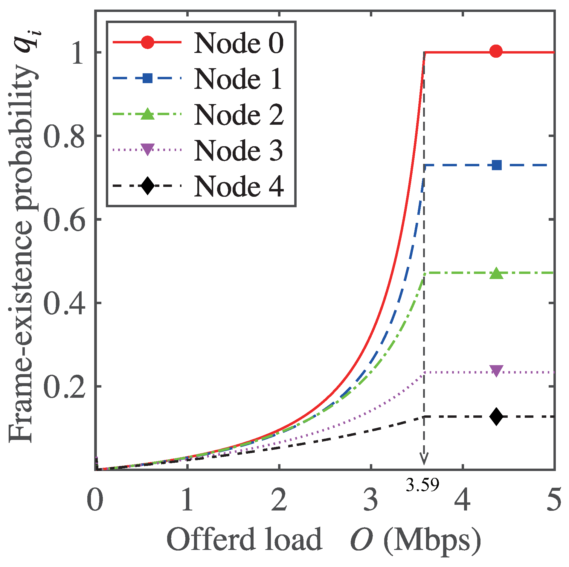
To confirm the maximum network throughputs, we first examine the frame existence probability . Figure 8 shows the frame existence probability as a function of offered load O in a five-hop network. As shown in Figure 8, frame existence probability value for each node differs because the impact from collisions, carrier-sensing, and secondary transmissions differs for each node. As shown in Figure 8, the frame existence probability for Node 0 reaches one at the network offered load of 3.59 Mbps while the frame existence probabilities for all other nodes are less than one. This means that Node 0 is the bottleneck node in the network. From Equation (28), the expression of frame-existence probability includes packet arrival rate , which depends on networks offered load O. This means the maximum value of frame-existence probability is 1 even in the network with the higher value of O. Because a node whose frame-existence probability is one has at least one data frame in its buffer, the node becomes a bottleneck in a multi-hop network [23]. As a result, end-to-end throughput in the multi-hop network is limited as the constant value of network offered load, which satisfies the frame-existence probability of the bottleneck node is 1. Therefore, the end-to-end throughput is limited as the constant value of the network offered load, which satisfies the frame-existence probability of the bottleneck node in the multi-hop network is 1. As the result the maximum throughput of the five-hop network is considered to be 3.59 Mbps.

Figure 8.
Frame existence of each node in the five-hop network as a function of offered load.
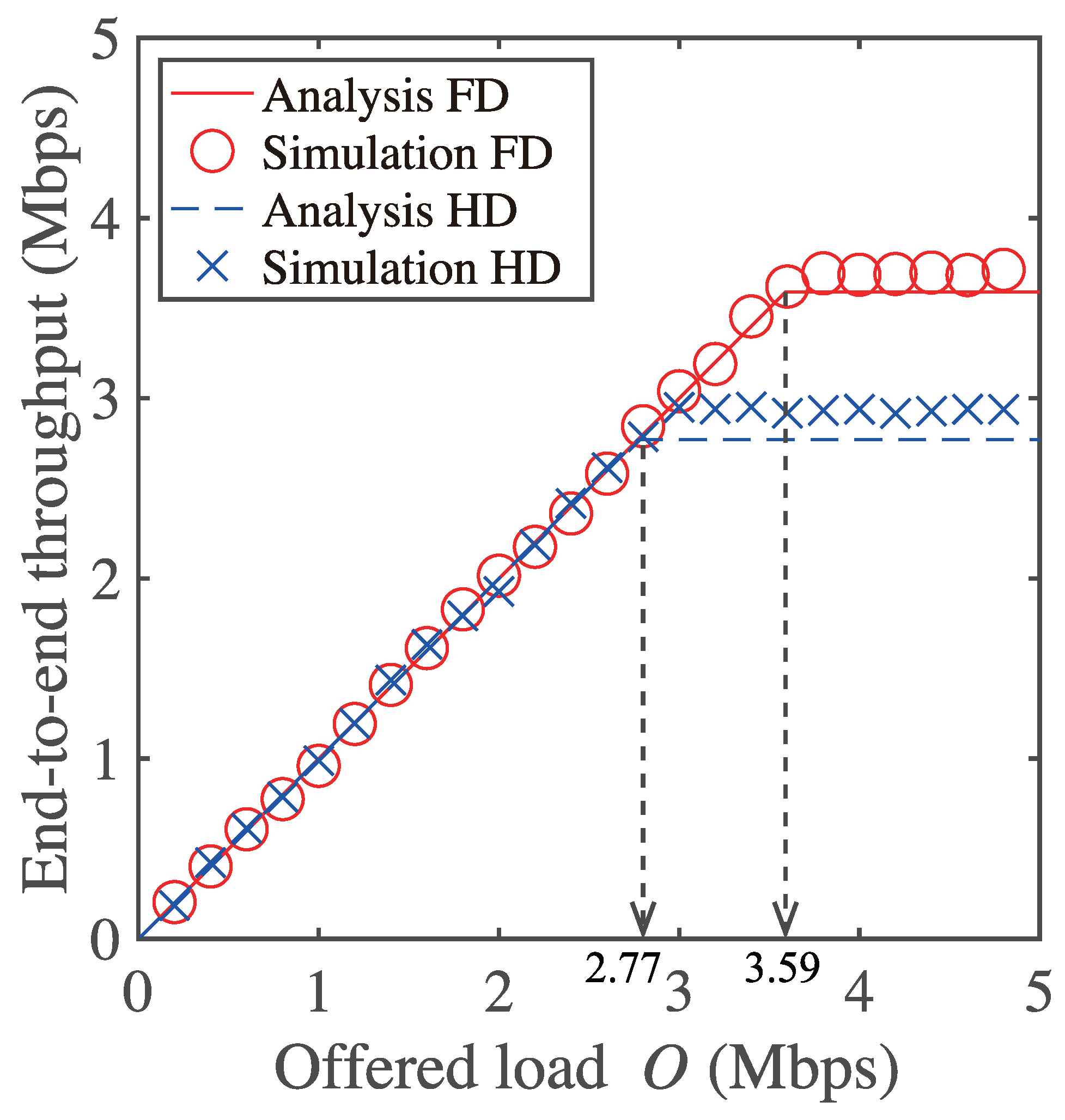
Figure 9 shows the end-to-end throughput in the network as a function of the offered load. As shown in Figure 9, the maximum end-to-end throughput is obtained as 3.59 Mbps. Thus, it is confirmed that the maximum throughput from the proposed model agrees with that of the simulation results. The analytical and simulation results of the maximum end-to-end throughputs for HD multi-hop networks are also shown in Figure 9. The analytical results of HD multi-hop networks can be calculated by assuming and , for . The results shown in Figure 8 and Figure 9 confirm the validity of the proposed analytical model.

Figure 9.
End-to-end throughput of the five-hop network as a function of offered load.
In addition, because RTS/CTS-based FD MAC provides higher maximum throughput, the enhancement of FD communication is confirmed. Because the maximum throughput of a HD multi-hop network with RTS/CTS is 2.77 Mbps, the gain of FD communication in the five hop network is derived as . This indicates that the FD communication does not achieve twice the network throughput in the string-topology multi-hop networks. From assumption 1, there is one network flow where only the source node (Node 0) generates the UDP data packet, and the relay nodes relay the data to the next node. The relay nodes generate no data packet by themselves. Therefore, when the secondary transmitter has no frame to relay, nodes in multi-hop networks often transmit DATA-frame in non-FD mode, i.e., HD transmission, even though they are capable of FD communication. This is why communication is not twice that of HD communication in string-topology multi-hop networks. The proposed model considers such unique operations in FD multi-hop networks in Equations (4) and (32).
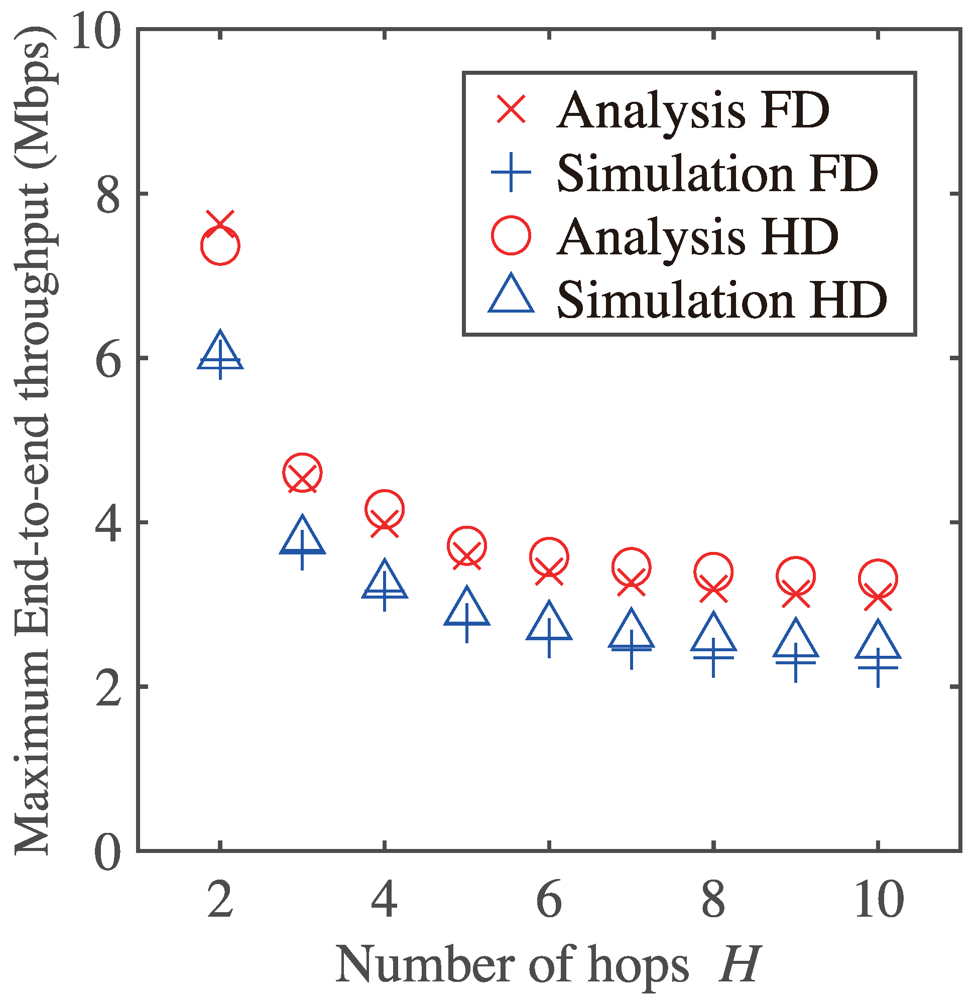
Figure 10 shows the maximum end-to-end throughput as a function of the number of hops H. It is seen from Figure 10 that the analytical results agree with simulation ones regardless of the number of hops. The maximum end-to-end throughputs for both FD and HD cases decrease as the number of hops increases.

Figure 10.
Maximum end-to-end throughput and gain of FD communication as a function of number of hops H.
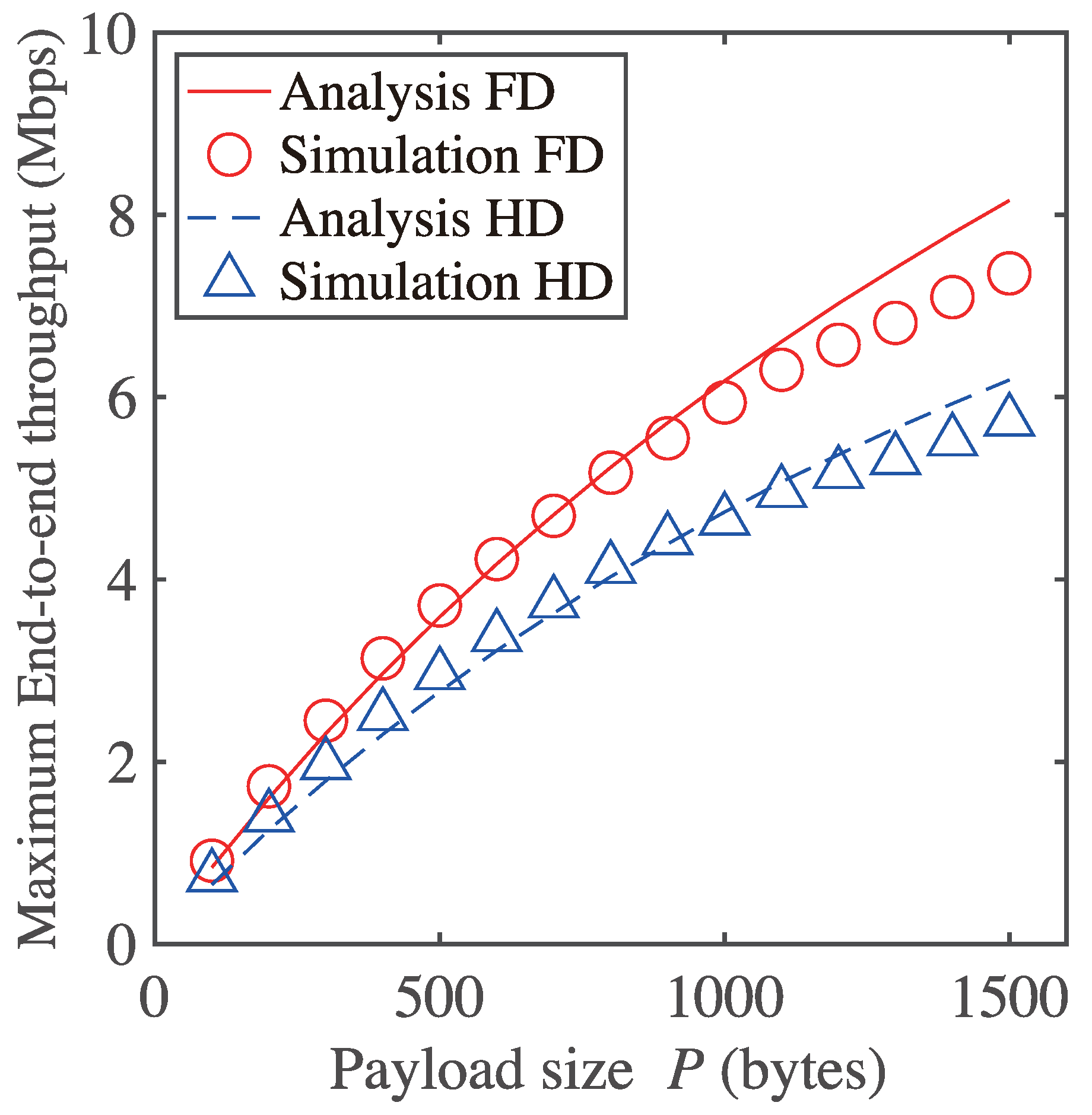
Figure 11 shows the maximum end-to-end throughput of the five-hop network as a function of payload size. It is evident from Figure 11 that the analytical results agree with the simulation results regardless of payload size. However, the analytical results differ for large P values because we assume the transmission failure probability is constant for any backoff stage. In Figure 5, Node 0 transmits RTS frames even if the receiver sets a NAV. The NAV duration depends on the payload size P. Therefore, Node 0 fails in the RTS frame transmissions repeatedly during longer NAV durations for larger P. Consequently, the transmission failure probability for each backoff stage is different for larger P. Thus, the maximum throughput for the RTS/CTS-based FD MAC in the analytical result is higher than that in the simulation result for large P values. Because this mechanism is common to HD multi-hop networks with RTS/CTS, the analytical results of HD multi-hop networks with RTS/CTS for large P values differs from the simulation results.

Figure 11.
Maximum end-to-end throughput of five–hop network as a function of payload size.
In the case of shorter payload size, on the other hand, it is seen from Figure 9, Figure 10 and Figure 11 that the simulation results beyond the analytical ones slightly. This is also because of the assumption. A node in the network does not fail the RTS frame transmissions repeatedly during shorter NAV durations for smaller P. Therefore, it is stated that the transmission failure probability in the higher backoff stage tends to be an extremely small value. Therefore, it is stated that the gap between the assumption and the behavior of multi-hop networks causes such quantitative errors. Even the proposed analytical expression includes some quantitative errors, which come from the assumption, and the qualitative verification of the proposed model is confirmed from all of the results presented in this paper. Additionally, qualitative verification is also important and useful from the viewpoint of clarifying complex behavior in networks.
5. Conclusions
This paper proposes a throughput analysis model for wireless multi-hop networks with RTS/CTS-based FD MAC. We derived an innovative expression of transmission airtime using successful and failed durations for frame transmissions in RTS/CTS-based FD MAC. The proposed model provides end-to-end throughput of multi-hop networks with RTS/CTS-based FD MAC for any number of hops and any payload size. Comparisons with simulation results confirmed the validity of the proposed model. The proposed analytical model can be easily applied to performance analysis for HD multi-hop networks with RTS/CTS. Therefore, the proposed model can be used to evaluate the performance of RTS/CTS multi-hop networks for FD and HD mathematically.
Author Contributions
Writing—original draft Y.Y.; writing—review and editing, S.S., K.S., H.H. and K.M. All authors have read and agreed to the published version of the manuscript.
Funding
This research was funded bythe Scholarship Foundation and Grant-in-Aid for scientific research (No. 17K14681) of JSPS.
Conflicts of Interest
The authors declare no conflict of interest.
References
- Thilina, K.M.; Tabassum, H.; Hossain, E.; Kim, D.I. Medium access control design for full-duplex wireless systems: Challenges and approaches. IEEE Commun. Mag. 2015, 53, 112–120. [Google Scholar] [CrossRef]
- Dibaei, M.; Ghaffari, A. Full-duplex medium access control protocols in wireless networks: A survey, Wireless Networks. Wirel. Netw. 2020, 26, 2825–2843. [Google Scholar] [CrossRef]
- Kim, D.; Lee, H.; Hong, D. A survey of in-band full-duplex transmission: From the perspective of PHY and MAC layers. IEEE Commun. Surv. Tutor. 2015, 17, 2017–2046. [Google Scholar] [CrossRef]
- Mohammady, R.D.; Naderi, M.Y.; Chowdhury, K.R. Performance analysis of CSMA/CA based medium access in full duplex wireless communications. IEEE Trans. Mob. Comput. 2016, 15, 1457–1470. [Google Scholar] [CrossRef] [Green Version]
- Sanada, K.; Mori, K. Performance analysis of full duplex MAC protocols for wireless local area networks with hidden node collisions. IEICE Trans. Commun. 2020, E103–B, 804–814. [Google Scholar] [CrossRef]
- Song, Y.; Qi, W.; Zhao, W.; Cheng, W. Full-Duplex MAC Protocol for CSMA/CA-Based Single-Hop Wireless Networks. Sensors 2019, 19, 2413. [Google Scholar] [CrossRef] [PubMed] [Green Version]
- Jain, M.; Choi, J.; Kim, T.; Bharadia, D.; Seth, S.; Srinivasan, K.; Levis, P.; Katti, S.; Sinha, P. Practical, real-time, full duplex wireless. In Proceedings of the 17th Annual International Conference on Mobile Computing and Networking (MobiCom), NewYork, NY, USA, 19–23 September 2011; pp. 301–312. [Google Scholar]
- Marlali, D.; Gurbuz, O. Design and performance analysis of a full-duplex MAC protocol for wireless local area networks. Ad Hoc Netw. 2017, 67, 53–67. [Google Scholar] [CrossRef]
- Cheng, W.; Zhang, X.; Zhang, H. RTS/FCTS mechanism based full-duplex MAC protocol for wireless networks. In Proceedings of the 2013 IEEE Global Communications Conference (GLOBECOM), Atlanta, GA, USA, 9–13 December 2013. [Google Scholar]
- Guimarães, L.M.; Bordim, J.L. An efficient MAC scheme for full-duplex communications on wireless networks. In Proceedings of the 2018 IEEE Wireless Communications and Networking Conference (WCNC), Barcelona, Spain, 15–18 April 2018. [Google Scholar]
- Alim, A.; Saruwatari, S.; Watanabe, T. Asym-FDMAC In-band full-duplex medium access control protocol for asymmetric traffic in wireless LAN. Wirel. Netw. 2020, 26, 807–822. [Google Scholar] [CrossRef]
- Tamaki, K.; Raptino, H.A.; Sugiyama, Y.; Bandai, M. Full duplex media access control for wireless multi-hop networks. In Proceedings of the 2013 IEEE 77th Vehicular Technology Conference (VTC Spring), Dresden, Germany, 2–5 June 2013. [Google Scholar]
- Sugiyama, Y.; Tamaki, K.; Saruwatari, S.; Watanabe, T. A wireless full-duplex and multi-hop network with collision avoidance using directional antennas. In Proceedings of the 2014 Seventh International Conference on Mobile Computing and Ubiquitous Networking (ICMU), Singapole, 6–8 January 2014; pp. 38–43. [Google Scholar]
- A-Kadri, M.O.; Aijaz, A.; Nallanathan, A. An energy-efficient full-duplex MAC protocol for distributed wireless networks. IEEE Wirel. Commun. Lett. 2016, 5, 44–47. [Google Scholar] [CrossRef] [Green Version]
- Chen, Y.D.; Chen, I.J.; Shih, K.P. An in-band full duplex MAC protocol with interference free for next generation WLANs. In Proceedings of the 2018 International Conference on Electronics Technology (ICET), Chengdu, China, 23–27 May 2018; pp. 407–410. [Google Scholar]
- Alim, M.A.; Kobayashi, M.; Saruwatari, S. Watanabe. In-band full-duplex medium access control design for heterogeneous wireless LAN. EURASIP J. Wirel. Commun. Netw. 2017, 2017, 83. [Google Scholar] [CrossRef]
- Fujimura, C.; Sanada, K.; Mori, K. Analytical expressions for end-to-End throughput of string-topology wireless full-duplex multi-hop networks. IEICE Trans. Commun. 2019, E102-B, 1160–1169. [Google Scholar] [CrossRef]
- Yin, W.; Hu, P.; Indulska, J.; Portmann, M.; Mao, Y. MAC-layer rate control for 802.11 networks: A survey. Wirel. Netw. 2020, 26, 3793–3830. [Google Scholar] [CrossRef]
- Holland, P.; Bahl, P. A rate-adaptive MAC protocol for multi-hop wireless networks. In Proceedings of the 7th Annual International on Mobile Computing and Networking (MOBICOM), Roma, Italy, 16–21 July 2001; Association for Computing Machinery: New York, NY, USA, 2001; pp. 236–251. [Google Scholar]
- Sugimoto, T.; Komuro, N.; Sekiya, H.; Sakata, S.; Yagyu, K. Maximum throughput analysis for RTS/CTS-used IEEE 802.11 DCF in wireless multi-hop networks. In Proceedings of the International Conference on Computer and Communication Engineering (ICCCE’10), Kuala Lumpur, Malaysia, 11–12 May 2010; pp. 1–6. [Google Scholar]
- Ng, P.C.; Liew, S.C.C. Throughput analysis of IEEE 802.11 multi-hop ad hoc networks. IEEE/ACM Trans. Netw. 2007, 15, 309–322. [Google Scholar] [CrossRef]
- Gao, Y.; Chiu, D.; Lui, J. Determining the end-to-end throughput capacity in multi-hop networks: Methodology and applications. In Proceedings of the 2006 ACM SIGMETRICS International Conference on Measurement and Modeling of Computer Systems, Saint Malo, France, 9–14 June 2006; Association for Computing Machinery: New York, NY, USA, 2006; pp. 39–50. [Google Scholar]
- Sanada, K.; Shi, J.; Komuro, N.; Sekiya, H. End-to-end delay analysis for IEEE 802.11 string-topology multi-hop networks. IEICE Trans. Commun. 2015, E98-B, 1284–1293. [Google Scholar] [CrossRef] [Green Version]
- Sanada, K.; Kumuro, N.; Li, Z.; Pei, Y.J.; Choi, H.; Sekiya, H. Generalized analytical expressions for end-to-end throughput of IEEE 802.11 string-topology multi-hop networks. Ad Hoc Netw. 2018, 70, 135–148. [Google Scholar] [CrossRef]
- Jawhara, I.; Moham, N.; Agrawalb, D.P. Linear wireless sensor networks: Classification and applications. J. Netw. Comput. Appl. 2011, 34, 1671–1682. [Google Scholar] [CrossRef]
- Kim, S.; Lee, S.; Choi, S. The impact of IEEE 802.11 MAC strategies on multi-hop wireless mesh networks. In Proceedings of the 2006 2nd IEEE Workshop on Wireless Mesh Networks, Reston, VA, USA, 25–28 September 2006; pp. 38–47. [Google Scholar]
- Leu, F.Y.; Huang, Y.T. Maximum capacity in chain-topology wireless mesh networks. In Proceedings of the 2008 Wireless Telecommunications Symposium, Pomona, CA, USA, 24–26 April 2008; pp. 250–259. [Google Scholar]
- Lai, W.; Ni, W.; Wang, H.; Liu, R.P. Analysis of average packet loss rate in multi-hop broadcast for VANETs. IEEE Commun. Lett. 2017, 22, 157–160. [Google Scholar] [CrossRef]
- Pinto, L.R.; Almeida, L.; Alzadeh, H. Aerial video stream over multi-hop using adaptive TDMA slots. In Proceedings of the 2017 IEEE Real-Time Systems Symposium (RTSS), Paris, France, 5–8 December 2017. [Google Scholar]
- Zhao, C.; Sun, W.; Fang, Z.; Wang, J.; Li, Q.; Zhang, H. End-to-end delay optimisation for IEEE 802.11 string topology multi-hop wireless networks in overhead transmission line system. IET Commun. 2021, 15, 487–495. [Google Scholar] [CrossRef]
- Bianchi, G. Performance analysis of the IEEE 802.11 distributed coordination function. IEEE J. Sel. Areas Commun. 2000, 18, 535–547. [Google Scholar] [CrossRef]
- Xu, K.; Gerla, M.; Bae, S. Effectiveness of RTS/CTS handshake in IEEE 802.11 abased ad hoc networks. Ad Hoc Netw. 2003, 1, 107–123. [Google Scholar] [CrossRef]
- Xu, K.; Gerla, M.; Bae, S. How effective is the IEEE 802.11 RTS/CTS handshake in ad hoc networks. In Proceedings of the Global Telecommunications Conference, GLOBECOM ’02, Taipei, Taiwan, 17–21 November 2002; pp. 72–76. [Google Scholar]
- Network Simulator 3. Available online: https://www.nsnam.org (accessed on 24 December 2021).
Publisher’s Note: MDPI stays neutral with regard to jurisdictional claims in published maps and institutional affiliations. |
© 2022 by the authors. Licensee MDPI, Basel, Switzerland. This article is an open access article distributed under the terms and conditions of the Creative Commons Attribution (CC BY) license (https://creativecommons.org/licenses/by/4.0/).