Article

ACE-M: Automated Control Flow Integrity Enforcement Based on MPUs at the Function Level

School of Electronic and Electrical Engineering, Kyungpook National University, Daegu 41566, Korea
*
Author to whom correspondence should be addressed.
Electronics 2022, 11(6), 912; https://doi.org/10.3390/electronics11060912
Submission received: 16 February 2022 / Revised: 9 March 2022 / Accepted: 13 March 2022 / Published: 15 March 2022
(This article belongs to the Special Issue Safety, Efficiency, and Reliability of Connected Smart Sensor Systems)

Abstract

:
Control-flow integrity(CFI) ensures that the execution flow of a program follows the control-flow graph(CFG) determined at compile time. CFI is a security technique designed to prevent runtime attacks such as return-oriented programming (ROP). With the development of the Internet of Things (IoT), the number of embedded devices has increased, and security and protection techniques in embedded systems have become important. Since the hardware-based CFI technique requires separate hardware support, it is difficult to apply to an embedded device that is already arranged. In this paper, we propose a function-level CFI technique named ACE-M, which uses the memory protection unit (MPU) included in most embedded devices. MPU may provide attributes such as read-write-execute to the memory area. ACE-M has three steps: (1) initiate—inserts an MPU-related function into a specific position; (2) profiling—provides information for MPU configuration. After the initation step, several pieces of information can be determined; (3) set—modify the already-inserted function’s arguments. We propose a design that supports the MPU. In our model, the MPU becomes a control flow monitor that detects control flow errors(CFEs), and the inserted codes cause the MPU to act as a control flow checker. If the program deviates from the original control flow, the MPU raises an exception since its corresponding area will not be included in the executable area. This approach not only verifies the target address but also guarantees the running position. Our technique can detect any modification of the program counter (PC) to an arbitrary address.

1. Introduction

Embedded devices are being used by many people around the world. As denoted in the term “Internet of Things,” these embedded processors are connected to the Internet, which provides convenience, and the number of devices has increased significantly. In this situation, the importance of safety and security issues for embedded systems is increasing, and there is still a need for continued research [1,2,3]. Embedded devices have some limitations such as power consumption, memory usage and computation performance. These limitations make it difficult to apply the security techniques used in general-purpose computers to embedded devices [1]. Currently, many small-scale embedded devices operate without an operating system (OS) due to performance overhead. Therefore, these limitations should be considered more in embedded systems than in general-purpose systems. For similar reasons, embedded systems are primarily written in the C programming language, which can efficiently manage resources and provide programmers with the ability to directly manage memory and optimize performance. However, C is an unsafe language and has vulnerabilities. Typically, due to the lack of boundary checks, it can often cause buffer overflow, which makes the program vulnerable to runtime attacks [4].
Stack smashing [5] and code reuse attacks (CRAs) are well-known runtime attacks; CRAs include return-oriented programming (ROP) [6,7] and jump-oriented Programming (JOP) [8]. These attacks are generally performed by overwriting the return address (RA) stored in the stack. Stack smashing is an attack in which the attacker can execute their malicious code on the stack by overwriting the RA using starting address of the injected code. These attacks were easily prevented by Data Execution Prevention (DEP) [9] or No-Execute (NX) protection [10], which block the code execution in memory areas such as the stack or heap. Such security technique prevent memory from being simultaneously writable and executable.
The CRA is a new attack that bypasses these security techniques. It utilizes small instruction sequences included in existing programs such as libraries. This instruction sequence is called a gadget, and the end of the gadget primarily contains branch statements such as ret or jump. By connecting these gadgets, an attacker can perform arbitrary operations.
A representative technique for preventing CRAs is control-flow integrity (CFI) [11,12,13]. CFI is a technique that ensures that a program follows a predefined control-flow graph (CFG) at compile time. In addition to runtime attacks, soft errors can cause a program to deviate from a pre-determined CFG. A soft error is a temporary error that occurs inside a semiconductor due to neutrons or alpha particles [14]. This error can cause bit flips in the register or memory. As a result, it can affect the control flow and violate the CFG [15]. Since it is not a physical error, it disappears when the device is restarted. However, most embedded systems require continuous operation, so detection of such soft errors is important to instantly correct improper execution of a program. In this paper, control flow errors (CFEs) include all cases that violate the predefined CFG, and we define that a control flow that deviates from the CFG is reffered to as a CFE. We propose a new method based on the memory protection unit (MPU) for detection of CFEs. Our technique guarantees CFI by inserting MPU configuration codes at compile time based on the low level virtual machine (LLVM) compiler [16]. An MPU is included in most embedded devices, and it can assign read-write-execute authority to some or all of the memory space. The idea for our technique involves setting the execute authority only in the area to be executed, and the area not to be executed is assigned to non-execute. Since our technique sets the area to be executed as the execute region in the MPU, runtime attacks can be detected through the MPU. The rest of the paper is organized as follows: In Section 2, we describe the necessary background. Section 3 provides the assumptions for our target and threat model that we want to protect using the proposed CFI technique. Section 4 explains our architecture and the principle for detecting CFEs. Section 5 introduces the code generation workflow. Section 6 analyzes the generated overhead when the technique is applied. Finally, we conclude in Section 7.

2. Background

2.1. Control-Flow Integrity

CFI is a security technique that prevents control flow tampering attacks such as CRAs [11,12]. The control flow instruction (CFIN), which changes the control flow, can be classified into three types. The first is direct call and jump, and the second is indirect call and jump. The third is return. In CFIN, the target address (TA) of the direct call and jump is explicitly included in the instruction. Therefore, if the code area is assumed to be read-only, it cannot be attacked because it cannot be modified. However, indirect call and jump is not determined at compile time but at runtime. Because a branch’s TA is stored in the register or memory, a program can operate with a control flow that is different from the original CFG through an attack such as those that modify the register or memory values. A return instruction pops the return address (RA) stored in the stack where it is pointed to by the PC. If an attacker modifies the RA, malicious code inserted by the attacker could execute. CFI can be divided into two types: forward-edge and backward-edge. Forward-edge CFI enforces the control flow of indirect call and jump, and backward-edge CFI ensures the control flow of a return instruction. In general, each CFI type is performed as follows: In the case of forward-edge CFI, when a function is called, even if an attacker modifies the value corresponding to the TA, the CFI can be checked by comparing it to the CFG, which is analyzed in advance. In the case of backward-edge CFI, it verifies whether the RA stored in the stack has been changed. In general, an indirect jump corresponding to forward-edge integrity can occur because the libraries, including standard libraries and application-specific libraries, are dynamically rather than statically linked to the application. Applications that use dynamically linked libraries use indirect jumps when calling library services. This indirect jump can be exploited because an attacker can manipulate the TA. An indirect call can occur when it is not possible to determine in advance which function will be called at compile time, such as by using a function pointer. In forward-edge integrity, the address of the next instruction is stored in the register or in memory. For this reason, the address of the next instruction cannot be accurately known until the instruction is executed at runtime, which can be abused by an attacker.

2.2. Related Works

A technique called a stack canary [17] has been proposed for determining whether the stored RA has been modified. It inserts a value with a difficult pattern between the local variable and the RA in the stack, and it then checks whether this value has been changed. If so, the RA has been modified. Although this technique mitigates attacks caused by buffer overflow, it is still vulnerable to run-time attacks that bypass such values. This is because the pattern does not guarantee RA integrity.
A shadow stack is a classic CFI technique [18], and it creates an additional shadow stack in the memory, which stores the RA and compares the RA in the original stack to that in the shadow stack before the return. It can verify whether the original RA has been modulated. However, this method eventually requires a separate security system that protects the shadow stack, and it supports only backward-edge integrity. Therefore, it must be used in addition to other forward-edge CFI techniques. RAD [19] protects the RA by inserting protection code in a similar way to the shadow stack. Additionally, there are some techniques with different points of view that mitigate CRAs. They find and remove gadgets or indirect branch instructions [20,21,22].
Hardware-based CFI is primarily developed in recent years. The main reason for this is that software-based CFI has a large performance overhead. Many architectures based on hardware are often integrated with processor’s instruction pipeline stages. ISA extension [23,24,25] such as adding special instruction also required modification of pipeline stages. In order to execute special instruction, it is necessary to modify the instruction decode (ID) stage. In addition, some recent works use debug interface to monitor program’s control flow. In this case, through a separate hardware connected to the external debug interface, it allows the hardware to check the control flow [26,27]. However, such hardware-based CFI needs specific hardward such as field-programmable gate array (FPGA) or application specific integrated circuit (ASIC). Hardware-based CFI does not differ from software-based CFI in detection method. This is because the control flow monitoring method is simlilar. There are various ways such as limiting the TA, activating the label or deactivation the label when branch instruction is executed [23]. Therefore, although the ACE-M proposed in this paper is software-based, it can be sufficiently designed as a hardware-based CFI.

2.3. Memory Protection Unit

In general, embedded devices do not include a memory management unit (MMU) which is responsible for memory management on a PC, because MMUs consume a large amount of memory capacity and require an OS when supporting virtual memory using page tables, resulting in cosiderable performance overhead. In other words, these devices are difficult to use in embedded systems, which have limited resources. However, MPUs support memory protection even in embedded devices, and they can be utilized in low-end embedded systems. Although an MPU does not support virtual memory, authority can be applied to the memory area. In general, the starting address and region size are required as inputs when designating the corresponding region. Access attributes such as read-write-execute can be set in each MPU region. There are several major restrictions on the MPU. The first is that the number of MPU regions is limited. In general, most MPUs have 8 or 16 regions. In this study, we use a system MPU with the 8 regions included in a cortex-m4. Second, in terms of size, each region should be set as a power of two. The minimum size of an area is 32 bytes and the maximum size is 4GB. Finally, the starting address should be a multiple of the region size. For example, if the region size is 0 × 100 (256 bytes in decimals), the starting address must be a multiple of 0 × 100. In addition, the MPU has a special feature related to our technique in that it assigns regions a priority. Regions with a bigger number have a higher priority; only a region with a higher priority can be employed when different regions overlap. This study, using these characteristics, provides a stepping-stone that can allow control flow to be restricted. Figure 1 depicts an example in which an MPU region is set. P and U refer to privileged mode and unprivileged mode, respectively, and R/W indicates whether read and write access is possible. X represents execute and XN represents non-execute. Each region is mapped to a part of memory as shown in Figure 1. When different regions overlap, that overlapped memory space has high region number.

2.4. Memory Space

A memory map refers to a map in which each area is separated and assigned to the actual memory space when the written code is made into an executable file. All code that is generally run is included in the code area, and variable areas for storing data such as stacks and heap are included in the SRAM. Figure 2 shows the memory model for the ARMv7E-M architecture. To understand our technique, it is necessary to also understand memory access attributes. Each memory area has default memory access attributes. These attributes include bufferable, cacheable and sharable. However, we only cover read-write-execute attributes here. The code memory region is an executable, and data memory can be stored in this area. An SRAM memory region is readable and writeable. Program code can be copied to the corresponding area and executed. Both memory regions are readable, writeable and executable. In addition, each memory region also has its own default memory access attributes. We use an MPU to give only the execute attribute to regions that need to be executed at a function level.

3. System Model

3.1. Assumptions

This section specifies the target system we aim to protect and describes the threat models that may arise. Our technique uses an MPU, which means that the target system is a low-end embedded system. Therefore, we suppose our target system is a bare-metal system with no OS. Applications running on target embedded system must be statically linked programs; they must also use a single stack. We assume a threat model since all CFEs are caused by vulnerabilities in the C code or semiconductor, including runtime attacks and soft errors. In examining this problem, we primarily cover runtime attacks such as stack smashing and CRAs.

3.2. Threat Model

In general, most attacks are made through buffer overflow caused by a lack of boundary checks, one of the vulnerabilities of the C language. Representative attacks using buffer overflow include stack smashing and CRAs, ROP and JOP. Our model aims to protect the system from these attacks. Stack smashing is performed through code injection, in which an attacker can inject the code he or she wants to execute into the stack. Using buffer overflow, attackers can inject code and overwrite the RA with the starting address of the malicious code. This strategy causes the program to deviate from its original control flow, and the attacker can take control. However, these exploits have become impossible due to DEP and NX protection [9,10]. By using such security techniques, the injected code is prevented from running. Such techniques can be similarly implemented by setting the SRAM memory region as a non-execute region using an MPU. However, CRAs are a threatening attack method that can bypass this type of security method. As the name suggests, CRAs are attacks that use a gadget, which is a code segment existing in the program. A gadget is a sequence of instructions used in CRA attacks, and segments that end in a branch sentence such as ret or jump are primarily referred to as a gadget. An ROP attack is an attack that changes the TA to the gadget address and chains each gadget so that attackers can perform arbitrary operations. CFI techniques are being studied to prevent such attacks.
An example of instruction pointer (IP) control using ROP is shown in Figure 3. The instruction segments ending with ret on the right side are gadgets, and they already exist in the program. The attacker connects these gadgets and controls the program to behave abnormally. An attacker can create an ROP payload including the useful gadgets and execute it by overwriting the starting address of the gadget he wants in each RA.

4. Proposed Architecture

4.1. Principle of CFE Detection

This section describes the approach and structure of ACE-M, the security technique we propose. ACE-M uses the MPU that most embedded devices have. The principle idea of ACE-M is to set entire code areas as non-execute areas, and to allow only the code area (function area) to be set as execute areas. Since the ACE-M technique can be implemented using three MPU regions, R0, R1, and R2, the remaining regions can be used elsewhere if necessary. In general, we use R1 for configuring the current executed region, and R2 for the next area, which is performed by the branch instruction. From this point of view, a function that sets R1 is performed at the beginning of all functions and after the call instruction, and an operation that sets R2 must be performed before the call or return instruction. R0 is set to non-execute at the beginning of the main. At this time, it should be noted that the MPU region for the main function must be set in R1 before setting R0 because if R0 is performed first, the entire code area cannot run. Our technique guarantees CFI, but which is maintained while the function is being executed. Therefore, it is possible to detect CFEs even in special situations in which the PC is changed due to a soft error. Figure 4 shows that the F1 function calls the F2 function using the MPU region and memory space. Figure 4a shows that the F1 function is currently being performed. In this case, F1 is also called by another function. That is, the F1 region is set in R2 before calling, and then the F1 region is set in the R1 region in F1. While F1 is being executed, it can be confirmed that both regions R1 and R2 include only F1. Figure 4b is the state before calling F2 from F1. Before calling F2, the setting for the F2 region was performed on R2. Figure 4c is the state in which F2 is being performed. Every function has inserted code in the first basic block (BB) that sets its area in R1. Therefore, Figure 4a,c show that when the function begins, R1 and R2 have the same area.
The return is performed in the same way as the call. Figure 5 likewise shows a situation in which F2 returns to F1. Figure 5a shows the state in which F2 is being executed. Figure 5b is the situation before the return. Before the return occurs, the setting for F1 is executed on R2. Figure 5c shows that when returning to F1, an operation in R1 that sets its own area is performed again in F1. In this way, only the function area currently being executed can be executed in the MPU area. We can verify abnormal control flow, when the PC points to an abnormal address that is not included in the MPU regions.

4.2. Automated Code Insertion for MPU Configuration

We insert MPU-related functions in two major steps. Both steps are important for ACE-M to perform normally. Through this process, we satisfy several conditions. First, the function region currently being executed is set in R1. Second, before CFINs such as calls and returns, the region in which the function will next be executed is set in R2. These two conditions are fundamental requirements that must be satisfied when using our technique. Setting R2 is similar to verifying the TA in general CFI. In Algorithm 1, F m p u is an MPU configuration function that allows the program to execute a specific area; it requires three arguments. These arguments include the starting address, size and region number. a r g s t m p includes temporary arguments. Since the starting address and size can be determined after inserting all of the MPU configuration code, only the region number can be fixed. I n e w is a new instruction that calls the MPU configuration function F m p u . Region number 1 is fixed in terms of the arguments of this function, which are inserted before the first instruction of the entry basic block and after the call instruction in any basic block. In addition, region number 2 is fixed in terms of the function’s arguments, which are inserted before the call instruction in any basic block. Setting a fixed region number in the temporary arguments can be utilized when re-setting the arguments to an accurate value.
However, there is still no guarantee of backward-edge CFI. Our technique is based on inserting an MPU configuration function to ensure CFI at compile time through LLVM transform pass. In general, it is impossible to specify where the function was called at compile time. These problems can be solved using the conditions we set earlier. All functions must be called by other functions. Therefore, we can predict that the region for the caller is set in R1 when the callee begins, and we can obtain the starting address and size by reading the MPU registers in R1 that are related.
In Algorithm 2, F r e a d is a function that reads the MPU registers in R1 that are related. F r e a d is inserted before the first instruction in the entry basic block and it returns a r g s . a r g s includes the starting address and size reading from the MPU register. F m p u is inserted before the return instruction in addition to a r g s . ACE-M can guarantee backward-edge CFI without allocating a separate memory area to the SRAM. A shadow stack is the typical CFI for such a method, and it must protect the shadow stack, which means that a separate security system is required. However, our technique enforces CFI only in terms of code memory area by using MPUs.
Algorithm 1 Insert Function
  • F m p u : MPU configuration function
  • I n e w : new instruction to be inserted
  • I f i r s t : first instruction in the basic block
  • I c a l l : function call instruction
  • a r g s t m p : temporary arguments used to create MPU configuration function
  • B B ^ : current basic block in the function
  • I ^ : current instruction in the basic block
  •  
  • Create_CallInst (F, a r g s t m p ): create a call instruction
  • Insert_before ( I o l d , I n e w ): insert a new instruction before the old instruction
  • getNextNode(): get next instruction’s pointer
  •  
  • I n e w Create_CallInst( F m p u , a r g s t m p )
  • if  B B ^ = = B B e n t r y  then
  •     if  I ^ = = I f i s r t  then
  •         Insert_before( I f i r s t , I n e w )
  •     end if
  • end if
  • if  I ^ = = I c a l l  then
  •     Insert_before( I ^ , I n e w )
  •     Insert_before( I ^ getNextNode(), I n e w )
  • end if
Algorithm 2 Read Caller Information in Callee
1:
F m p u : MPU configuration function
2:
F r e a d : read MPU register to obtain starting address and size of a caller
3:
I n e w : new instruction to be inserted
4:
a r g s : caller function’s starting address and size
5:
I ^ : current instruction in BB
 
 
6:
Create_CallInst (F, a r g s t m p ): create call instruction
7:
Insert_before ( I o l d , I n e w ): insert new instruction before the old instruction
 
 
8:
I n e w Create_CallInst( F r e a d )
9:
if B B ^ = = B B e n t r y  then
10:
    if  I ^ = = I f i s r t  then
11:
         a r g s Insert_before( I f i r s t , I n e w )
12:
    end if
13:
end if
14:
I n e w Create_CallInst( F m p u , a r g s )
15:
if  B B ^ = = B B e x i t  then
16:
    if  I ^ = = I l a s t  then
17:
        Insert_before( I l a s t , I n e w )
18:
    end if
19:
end if

4.3. Profiling & Function Layout

In Section 4.2, we inserted all the necessary MPU configuration function call instructions. However, in this step, the arrangement of the function has not yet been determined, and therefore, the MPU configuration function with its temporary arguments is inserted. At this point, the size of the final function can be determined. and we can extract the function size. ACE-M guarantees CFI by using MPU regions at the function level. In general, each function should be able to be assigned to a single MPU region. To set an MPU region, there are requirements that must be met. First, the size must be a power of 2 and range from at least 32 bytes to 4 GB. In addition, the starting address of the MPU area should be a multiple of the region size. To satisfy these conditions, the function must be located at a specific address. Therefore, it is necessary to amend the linker script. Figure 6 shows the memory layout of the function in the code area. To construct such a memory layout, the first piece of information that must be determined is the size of the function. Since the MPU region can be specified only once the size of the function is determined.
In ACE-M, the functions are placed in descending order. The sizes of F1 and F2 are larger than 128 bytes and smaller than 256 bytes. Therefore, each MPU region that covers F1 and F2 has a size of 256 bytes. Additionally, the function must be located at a multiple of 0 × 100 in the form of a Hex of 256 bytes. Likewise, F3 may be located at a multiple of 0 × 80 because it may be set as an MPU area of 128 bytes. In this paper, we focused on security performance rather than code size. Code area layout can be optimized if necessary.

4.4. Set Accurate Arguments

We wrote a linker script, placed each function at a specific address in the physical memory, and extracted the starting address and size for each function in the previous step. In this step, the temporary arguments can be modified correctly. In Algorithm 3, we first find the call instruction and check whether the called function is F m p u . We also read the arguments of the called F m p u . If the value of R n u m in the arguments is 1, we modify the arguments to fit the current function region. If the value of R n u m in the arguments is 2, it means the next instruction is the call instruction. We can check the next instruction’s called function and modify the arguments of F m p u .
Algorithm 3 Set Arguments
1:
F m p u : MPU configuration function
2:
F c a l l e d : called function from function call instruction
3:
a r g s c : arguments of the current function
4:
a r g s n : arguments of the next function
5:
R n u m : region number included in arguments
6:
I ^ : current instruction in BB
 
 
7:
setOperand( a r g s ): set argument of function
 
 
8:
if I ^ = = I c a l l  then
9:
    if  I ^ F c a l l e d = = F m p u  then
10:
        if  F c a l l e d a r g s R n u m = = 1  then
11:
            F c a l l e d setOperand( a r g s c )
12:
        end if
13:
        if  F c a l l e d a r g s R n u m = = 2  then
14:
            F c a l l e d setOperand( a r g s n )
15:
        end if
16:
    end if
17:
end if

4.5. Transformed Function for the ACE-M Technique

The code for an MPU region configuration is required for each function to apply ACE-M. A function that does not contain a call instruction within the function only transforms the first BB and the last BB, as shown in Figure 7. Basically, in the first BB, the current function area is set at R1. In the last BB, int R2, the area for the caller is set to return to the caller. In ACE-M, the function region currently being EXECUTED is set in R1. That is, when moving to the callee using a call instruction, the area of the caller is set in R1. Based on this configuration, the callee is the first to back up the information on the caller, and the MPU settings can be executed using this information before the return instruction. The function including the call can be confirmed using Figure 8. This process is the same as setting the target function area to be called at R2 before calling and setting the function area currently being performed at R1 when returning. By inserting the MPU configuration code into the function, an attack occurring at runtime may be detected.

4.6. Detection Scenario Using ACE-M

Figure 9 shows an execution scenario in which a CFE is detected. During this process, Function B is called from Function A and returned from Function B to Function A. It is assumed that the address of Function C overwrites the RA while returning from Function B. In this case, the last MPU configuration performed corresponds to ➃. Function C is not included in the R1 and R2 regions at that time and thus cannot be executed by R0. This situation is considered a CFE, and the MPU raises a memory management fault.

4.7. Transformed Function for ACE-M Technique

Our technique can prevent stack smashing as well as CRAs. In this paper, we assume that the program is executed only in the code memory region. That is, the region excluding the code memory region becomes an NX area. This assumption may be simply satisfied because it is possible to set the program so that it will not be executed in the SRAM through the MPU. In addition, this method becomes a technique that blocks a stack smashing attack. CRAs such as ROP and JOP can also be detected using the proposed method. ROP and JOP eventually perform any operations the attacker intends by chaining a gadget in the code domain. To execute gadgets, the PC must point to the starting address. This area is not included in the MPU region that we have set to satisfy the CFI. This limitation can be enforced because our technique pre-sets the function area to be branched rather than comparing the TA, and the MPU detects CFEs. However, there are some limitations to our work. The technique we propose increases the performance overhead and code size, which are limitations of existing software-based CFI. In addition, fragmentation occurs between functions in the memory layout process that maps the function to the MPU area. In addition, we specify the environment for the executing program to ensure security, our system is bare-metal, and the program must be performed using a single thread, which is necessary because the MPU mapped to each thread must be separately managed, and requires its own function modifications. ACE-M cannot be applied when using library functions other than those that are already compatible. Since most of the overhead that occurs due to our technique is caused by the insertion of the MPU setting function, optimization of these functions can lead to a reduction in overhead. We will leave this optimization step as a future task.
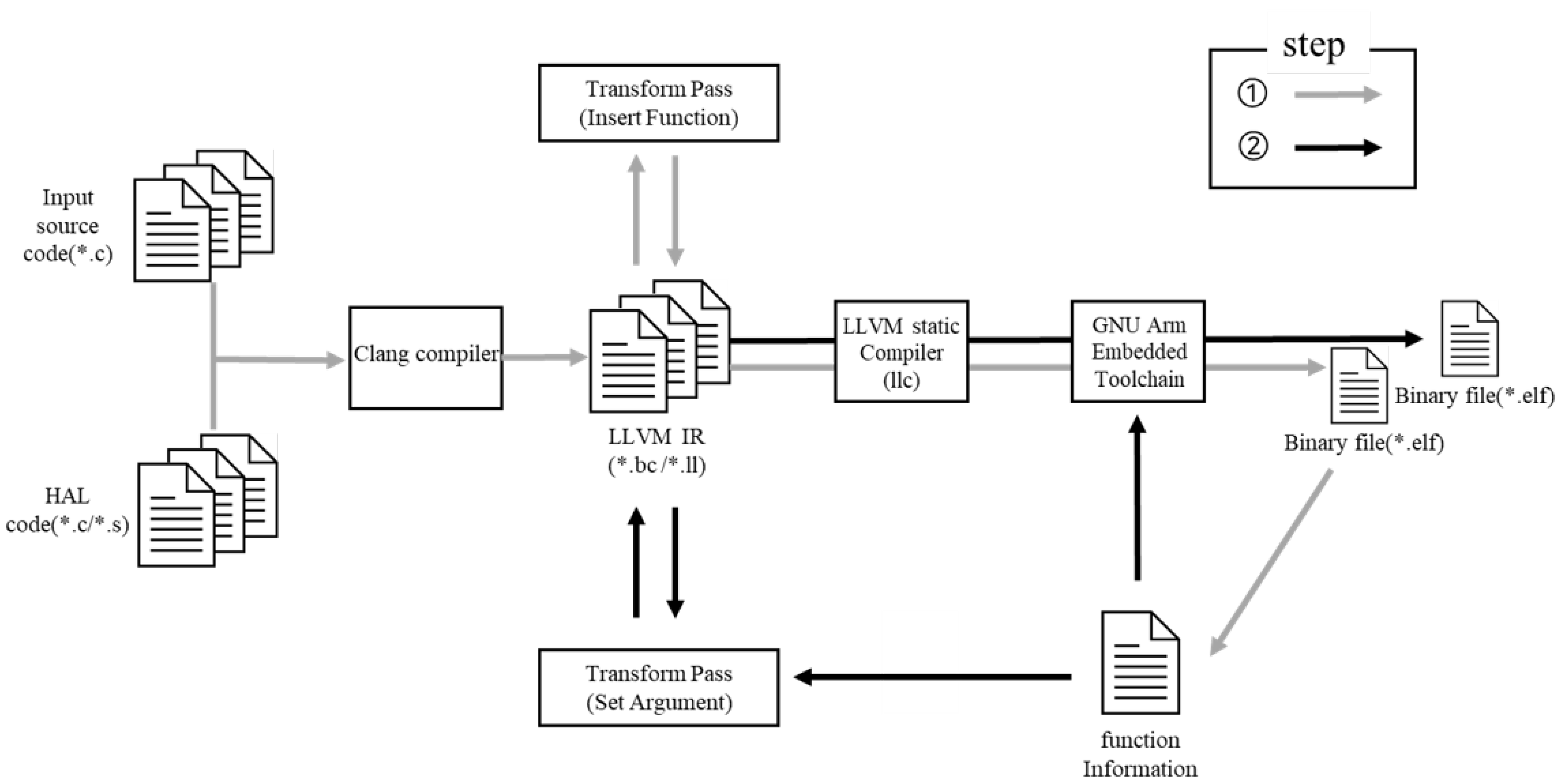
5. Code-Generation

In this section, we explain our workflow for generating the binary code to which our technique is applied as shown in Figure 10. In general, a compiler consists of front-end, middle-end, and back-end stages. In this case, a compiler is required as much as the product of the programming language and the execution architecture type. LLVM has been developed to cope with this problem.

5.1. Clang

The Clang compiler compiles languages such as C, C++, and Objective-C, and it works with LLVM. Clang is primarily used as the LLVM front-end. The source code, which is written in C, is compiled into LLVM intermediate representation (LLVM IR), which is provided by LLVM.

5.2. Optimization in Middle-End

In the middle-end, LLVM IR can be analyzed and transformed using LLVM Pass. An existing pass or custom pass can be used during optimization. We implemented our custom pass, which inserts a function and a pass that sets the Arguments.

5.3. Binary Code Generation

The LLVM static compiler compiles the LLVM IR code into a target file suitable for the system’s architecture. Finally, we generate an executable object file using a linking process through a linker provided by the GNU Arm Embedded Toolchain.

6. Performance Evaluation

In this section, we evaluate the ACE-M technique and analyze its overhead. The evaluation metrics include the detection rate, cycle count overhead and code size.

6.1. Evaluation Environments and Benchmarks

To verify the validity of the proposed ACE-M technique, we evaluate each metrics in the STM32CubeIDE debug environment, and the STM32F407VG development board was used. We use Embench-iot, which is included in open source Benchmarks for Embedded Platform. However, ACE-M requires modification of all running functions, so benchmarks with library functions were excluded.

6.2. Detection Rate

In computer security, the ability to execute arbitrary commands or code is called arbitrary code execution (ACE). We evaluated our detection performance by imitating it in a debugging environment. ACE is generally conducted through control of the running process’s instruction pointer. Instruction pointers generally refer to the PC, and the PC refers to the address of the instruction to be executed next. Therefore, it is possible to check whether a CFE has occurred by arbitrarily changing the PC value, and if a CFE is generated, the MPU raise a memory management fault. When modifying the PC value in the memory address, excluding the function included in the MPU region, it correctly made detections as 100% of the time. In addition, since our technique alternates between using MPU regions R1 and R2, it can also make detections when moving to other functions not in the CFINs. For example, a program may not return to the next instruction of the call. In that case, it can detect a CFE when the next MPU code is executed.

6.3. Execution Cycle Counter Overhead Analysis

We measured the execution time using a data watch and trace unit (DWT) containing a clock cycle register (CYCCNT) in a Cortex-M3/M4. Figure 11 compares the basic benchmarks and benchmarks with ACE-M using the CYCCNT. The benchmarks had performance overheads of 56.28%, 8.56%, 6.98%, 20.63%, 30.76%, 4.07% and 3.88%.
In our technique, MPU configuration codes are inserted to ensure CFI. Since these are the same size in every existing function, a relatively small function can incur a considerable overhead. Therefore, it was confirmed that an average of 5.87% overhead occurred in the benchmarks, where the CYCCNT is approximately 6000 or more due to the relatively large size of the program. Although not expressed in the graph, in the case of the crc_32 benchmark, the performance overhead increased by approximately 80%, which confirms that small functions were continuously called in a loop. After that, we made this small function an inline function and evaluated it again; it recorded an overhead of only 0.76%.

6.4. Code Size Overhead

Figure 12 shows the increase in code size that occurs for a major single function in the benchmark. The code used for MPU setting is inserted in the basic function. The actual function size is the size of the existing function plus the configuration function, but occupied size becomes larger because the rest of the region cannot be used for other purposes. The best case is a case in which the configuration code inserted is a multiplier of 2 or a bit smaller. Conversely, the worst case is a case in which the configuration function is added and slightly exceeds a multiplier of 2. This scenario may cause a problem in which more memory is used, up to the corresponding function size.

7. Conclusions

In this paper, we propose ACE-M, which is based on the MPU. For our technique, we insert MPU configuration codes into functions. This strategy is similar to those used in previous studies. However, ACE-M does not compare TA values to enforce CFI. The MPU can provide execute authority to the function region. Unlike other techniques, these settings are valid not only for CFINs but also while the corresponding function is being executed. For this reason, we could detect CFEs caused by soft errors. However, since the configuration code must be inserted, the size of the code increases and the time overhead is inevitably incurred. We measured the execution time overhead using the CYCCNT register included in a Cortex-M3/M4, and the results showed an overhead of approximately 5.87% when executing a program with an overall CYCCNT exceeding 6000. It is possible to improve the security of existing small low-end embedded systems using an MPU. Our technique’s coverage is only for the bare-metal systems, but this approach can be applied to specific processes in other systems. In future work, we will work on optimizing the inserted code and memory layout so that it has a lower overhead. In addition, it seems that such overhead can be lowered through hardware-based design adopting the method of ACE-M while maintaining the detection rate.

Author Contributions

Conceptualization, S.L.; methodology, S.L. and J.C.; software, S.L.; validation, S.L. and J.C.; formal analysis, S.L.; investigation, S.L.; data curation, S.L.; writing—original draft preparation, S.L.; writing—review and editing, S.L.; visualization, S.L.; supervision, J.C.; project administration, S.L.; funding acquisition, J.C. All authors have read and agreed to the published version of the manuscript.

Funding

This work was supported by the National Research Foundation of Korea (NRF) grant funded by the Korean government (MSIT) (No. NRF-2020R1A2C1013836) and the BK21 FOUR project funded by the Ministry of Education, Korea (4199990113966).

Conflicts of Interest

The authors declare no conflict of interest. The funders had no role in the design of the study; in the collection, analyses, or interpretation of data; in the writing of the manuscript, or in the decision to publish the results.

Abbreviations

The following abbreviations are used in this manuscript:
CFIControl Flow Integrity
CFINControl Flow Instruction
CFGControl Flow Graph
CFEControl Flow Error
LLVMLow Level Virtual Machine
LLVM IRLLVM Intermediate Representation
BSBinary Search
CNTCount
EXExponential Integral
FIFibonacci
JCJanne Complex
SESelect
UDUpper Decomposition

References

  1. Ravi, S.; Raghunathan, A.; Kocher, P.; Hattangady, S. Security in embedded systems: Design challenges. ACM Trans. Embedded Comput. Syst. (TECS) 2004, 3, 461–491. [Google Scholar] [CrossRef]
  2. Costin, A.; Zaddach, J.; Francillon, A.; Balzarotti, D. A large-scale analysis of the security of embedded firmwares. In Proceedings of the 23rd USENIX Security Symposium USENIX Security 14, San Diego, CA, USA, 20–22 August 2014; pp. 95–110. [Google Scholar]
  3. Sadeghi, A.R.; Wachsmann, C.; Waidner, M. Security and privacy challenges in industrial internet of things. In Proceedings of the 2015 52nd ACM/EDAC/IEEE Design Automation Conference (DAC), San Francisco, CA, USA, 8–12 June 2015; pp. 1–6. [Google Scholar]
  4. Smith, N.P. Stack Smashing Vulnerabilities in the UNIX Operating System; Computer Science Department, Southern Connecticut State University: New Haven, CT, USA, 1997. [Google Scholar]
  5. One, A. Smashing the stack for fun and profit. Phrack Mag. 1996, 7, 14–16. [Google Scholar]
  6. Shacham, H. The geometry of innocent flesh on the bone: Return-into-libc without function calls (on the x86). In Proceedings of the 14th ACM Conference on Computer and Communications Security, Alexandria, VA, USA, 2 November–31 October 2007; pp. 552–561. [Google Scholar]
  7. Roemer, R.; Buchanan, E.; Shacham, H.; Savage, S. Return-oriented programming: Systems, languages, and applications. ACM Trans. Inf. Syst. Secur. (TISSEC) 2012, 15, 1–34. [Google Scholar] [CrossRef]
  8. Bletsch, T.; Jiang, X.; Freeh, V.W.; Liang, Z. Jump-oriented programming: A new class of code-reuse attack. In Proceedings of the 6th ACM Symposium on Information, Computer and Communications Security, Hong Kong, China, 22–24 March 2011; pp. 30–40. [Google Scholar]
  9. Andersen, S.; Abella, V. Data Execution Prevention. Changes to Functionality in Microsoft Windows XP Service Pack 2, Part 3: Memory Protection Technologies. Available online: http://technet.microsoft.com/en-us/library/bb457155.aspx (accessed on 1 February 2022).
  10. Team, P. PaX Non-Executable Pages Design & Implementation. Available online: http://pax.grsecurity.net/docs/noexec.txt (accessed on 1 February 2022).
  11. Abadi, M.; Budiu, M.; Erlingsson, U.; Ligatti, J. Control-flow integrity principles, implementations, and applications. ACM Trans. Inf. Syst. Secur. (TISSEC) 2009, 13, 1–40. [Google Scholar] [CrossRef]
  12. Abadi, M.; Budiu, M.; Erlingsson, U.; Ligatti, J. Control-Flow Integrity. In Proceedings of the 12th ACM Conference on Computer and Communications Security (CCS ’05), Alexandria, VA, USA, 7–11 November 2005; Association for Computing Machinery: New York, NY, USA, 2005; pp. 340–353. [Google Scholar] [CrossRef]
  13. Burow, N.; Carr, S.A.; Nash, J.; Larsen, P.; Franz, M.; Brunthaler, S.; Payer, M. Control-flow integrity: Precision, security, and performance. ACM Comput. Surv. (CSUR) 2017, 50, 1–33. [Google Scholar] [CrossRef]
  14. Baumann, R. Soft errors in advanced computer systems. IEEE Des. Test Comput. 2005, 22, 258–266. [Google Scholar] [CrossRef]
  15. Didehban, M.; Shrivastava, A.; Lokam, S.R.D. NEMESIS: A software approach for computing in presence of soft errors. In Proceedings of the 2017 IEEE/ACM International Conference on Computer-Aided Design (ICCAD), Irvine, CA, USA, 13–16 November 2017; pp. 297–304. [Google Scholar]
  16. Lattner, C.; Adve, V. LLVM: A compilation framework for lifelong program analysis & transformation. In Proceedings of the International Symposium on Code Generation and Optimization (CGO 2004), San Jose, CA, USA, 20–24 March 2004; pp. 75–86. [Google Scholar]
  17. Cowan, C.; Pu, C.; Maier, D.; Walpole, J.; Bakke, P.; Beattie, S.; Grier, A.; Wagle, P.; Zhang, Q.; Hinton, H. Stackguard: Automatic adaptive detection and prevention of buffer-overflow attacks. In Proceedings of the USENIX Security Symposium, San Antonio, TX, USA, 26–29 January 1998; Volume 98, pp. 63–78. [Google Scholar]
  18. Dang, T.H.; Maniatis, P.; Wagner, D. The performance cost of shadow stacks and stack canaries. In Proceedings of the 10th ACM Symposium on Information, Computer and Communications Security, Singapore, 17 March–14 April 2015; pp. 555–566. [Google Scholar]
  19. Chiueh, T.C.; Hsu, F.H. RAD: A compile-time solution to buffer overflow attacks. In Proceedings of the Proceedings 21st International Conference on Distributed Computing Systems, Mesa, AZ, USA, 16–19 April 2001; pp. 409–417. [Google Scholar]
  20. Salwan, J. ROPgadget—Gadgets Finder and Auto-Roper. Available online: http://shell-storm.org/project/ROPgadget/ (accessed on 1 February 2022).
  21. Zhang, M.; Sekar, R. Control flow integrity for COTS binaries. In Proceedings of the 22nd USENIX Security Symposium (USENIX Security 13), Washington, DC, USA, 14–16 August 2013; pp. 337–352. [Google Scholar]
  22. Pappas, V.; Polychronakis, M.; Keromytis, A.D. Transparent ROP exploit mitigation using indirect branch tracing. In Proceedings of the 22nd USENIX Security Symposium (USENIX Security 13), Washington, DC, USA, 14–16 August 2013; pp. 447–462. [Google Scholar]
  23. Davi, L.; Koeberl, P.; Sadeghi, A.R. Hardware-assisted fine-grained control-flow integrity: Towards efficient protection of embedded systems against software exploitation. In Proceedings of the 2014 51st ACM/EDAC/IEEE Design Automation Conference (DAC), San Francisco, CA, USA, 1–5 June 2014; pp. 1–6. [Google Scholar]
  24. Davi, L.; Hanreich, M.; Paul, D.; Sadeghi, A.R.; Koeberl, P.; Sullivan, D.; Arias, O.; Jin, Y. HAFIX: Hardware-assisted flow integrity extension. In Proceedings of the 2015 52nd ACM/EDAC/IEEE Design Automation Conference (DAC), San Francisco, CA, USA, 8–12 June 2015; pp. 1–6. [Google Scholar]
  25. Christoulakis, N.; Christou, G.; Athanasopoulos, E.; Ioannidis, S. HCFI: Hardware-enforced control-flow integrity. In Proceedings of the Sixth ACM Conference on Data and Application Security and Privacy, New Orleans, LA, USA, 9–11 March 2016; pp. 38–49. [Google Scholar]
  26. Das, S.; Zhang, W.; Liu, Y. A fine-grained control flow integrity approach against runtime memory attacks for embedded systems. IEEE Trans. Very Large Scale Integr. (VLSI) Syst. 2016, 24, 3193–3207. [Google Scholar] [CrossRef]
  27. Francillon, A.; Perito, D.; Castelluccia, C. Defending Embedded Systems against Control Flow Attacks. In Proceedings of the Proceedings of the First ACM Workshop on Secure Execution of Untrusted Code (SecuCode ’09), Chicago, IL, USA, 9 November 2009; Association for Computing Machinery: New York, NY, USA, 2009; pp. 19–26. [Google Scholar] [CrossRef] [Green Version]
Figure 1. An example of how the MPU provides memory access attributes to each region and how it works on Memory space.
Electronics 11 00912 g001
Figure 2. Example of a memory map.
Electronics 11 00912 g002
Figure 3. Diagram of an ROP attack.
Electronics 11 00912 g003
Figure 4. Example of program execution: (a) F1 is executed, (b) F1 calls F2 and (c) F2 is executed.
Electronics 11 00912 g004
Figure 5. Example of program execution: (a) F2 is executed, (b) F2 returns to F1 and (c) F1 is executed.
Electronics 11 00912 g005
Figure 6. Code area layout for ACE-M.
Electronics 11 00912 g006
Figure 7. Function with no call instruction.
Electronics 11 00912 g007
Figure 8. Function with a call instruction.
Electronics 11 00912 g008
Figure 9. Detection scenario example that shows the configuration of each region.
Electronics 11 00912 g009
Figure 10. Overall structure of the ACE-M technique.
Electronics 11 00912 g010
Figure 11. Percentage of execution time overhead.
Electronics 11 00912 g011
Figure 12. Function size overhead.
Electronics 11 00912 g012
Publisher’s Note: MDPI stays neutral with regard to jurisdictional claims in published maps and institutional affiliations.

