Review

The Design Considerations and Challenges in MOS-Based Temperature Sensors: A Review

School of Microelectronics, Shandong University, 1500 Shunhua Road, Jinan 250101, China
Electronics 2022, 11(7), 1019; https://doi.org/10.3390/electronics11071019
Submission received: 17 February 2022 / Revised: 19 March 2022 / Accepted: 22 March 2022 / Published: 24 March 2022
(This article belongs to the Section Circuit and Signal Processing)

Abstract

:
This review paper categorizes the state-of-the-art MOS (metal oxide semiconductor)-based temperature sensors according to their thermal sensing principles, including: type I, the logic, saturation and linear MOS-based temperature sensors; type II, the subthreshold MOS-based temperature sensors; and type III, the gate leakage-based temperature sensors. It also discusses in detail the design considerations and challenges of MOS-based temperature sensors, in terms of area, energy efficiency, supply voltage, inaccuracy, noise, as well as process and power supply variations. Based on the aforementioned discussions, the paper concludes that the future MOS-based temperature sensors will mostly likely be based on subthreshold MOS operation, with better trade-offs between area, energy efficiency and accuracy, and with reduced power supply sensitivity and level, as well as a lower-cost, fewer-point calibration method.

1. Introduction

In industry, common temperature sensors include integrated circuit (IC) temperature sensors, thermistors, the resistor temperature detector (RTD) and thermocouples, among which, in turn, the temperature measurement range and the sensor size increase, in general. For example, the ultrasonic transducers, which were reviewed in [1], are capable of measuring temperatures higher than 150 °C in hazardous environments, belonging to the RTD category. IC temperature sensors are required for applications such as human body temperature monitoring, VLSI thermal monitoring and management, etc. Modern microprocessors, such as Intel i7, rely on the on-chip temperature sensors to trigger an alert when their temperatures reach a predefined threshold. The speed of the fans on the microprocessors are adjusted according to the temperature sensors’ readings. Typical thermal management approaches include dynamic voltage scaling and dynamic frequency scaling, which reduce the voltage or the frequency dynamically for circuitries at the hotspots [2]. For high voltage, high temperature applications (e.g., between −20 and 180 °C), a thermal shutdown circuit is employed and its output voltage drops as its sensed temperature reaches a threshold, e.g.,140 °C [3]. Its sensing core consists of a bipolar junction transistor (BJT) whose current decreases with temperature. As its current crosses the reference level through a current mirror, the output MOS transistor is driven into its triode region and its drain-source (output) voltage drops to nearly ground level, hence turning off the circuits that follow. The state-of-the-art IC temperature sensors can be categorized into three major types: the MOS based [4,5,6,7,8,9,10,11,12,13,14,15,16,17,18,19,20,21,22,23,24,25,26,27,28,29,30,31,32,33,34], the BJT based [35,36,37,38,39,40,41,42,43,44,45,46,47,48,49,50,51,52,53,54,55,56,57,58,59,60,61,62,63,64,65,66,67,68,69,70,71,72,73,74,75], and the (polysilicon) resistor based [76,77,78,79,80,81,82,83,84,85,86,87,88,89,90,91,92,93,94,95,96,97,98,99,100,101,102,103,104,105,106] types. Figure 1a–c compare the above-mentioned three types on their area and resolution figures of merit (RFOM), as well as their supply voltage levels, in the papers published in [4,5,6,7,8,9,10,11,12,13,14,15,16,17,18,19,20,21,22,23,24,25,26,27,28,29,30,31,32,33,34,35,36,37,38,39,40,41,42,43,44,45,46,47,48,49,50,51,52,53,54,55,56,57,58,59,60,61,62,63,64,65,66,67,68,69,70,71,72,73,74,75,76,77,78,79,80,81,82,83,84,85,86,87,88,89,90,91,92,93,94,95,96,97,98,99,100,101,102,103,104,105,106]. Figure 2 shows the trade-offs between energy efficiency and area for all three types. A few observations can be made from Figure 1 and Figure 2, as follows: (1) The smallest sensor belongs to the MOS-based type, for the last 5 years; (2) Among the temperature sensors that have the smallest RFOM, the majority belong to the resistor-based type. RFOM is calculated as energy/conversion∙resolution2 and is a representation of the energy efficiency in reference to its resolution; However, the MOS-based type is better than its BJT counterpart, for RFOM, on average (Figure 1b); (3) The majority of sensors with the lowest supply voltage belong to the MOS-based type (Figure 1c). (4) The MOS and the resistor-based types have better energy efficiency and area trade-offs than their BJT-based counterparts (Figure 2), in general. For VLSI thermal management, multiple temperature sensors are required at hotspots for thermal monitoring and they are preferred to share the digital voltage supply level, which scales with the technology nodes. Therefore, to target for small area and low voltage supply applications, this review focuses on the MOS-based temperature sensors. This review is organized as follows. Section 2 describes the operating principles of different subtypes of MOS-based temperature sensors, which are categorized according to their thermal sensing principles, namely: type I, the logic, saturation and linear MOS-based temperature sensors; type II, the subthreshold MOS-based temperature sensors; and type III, the gate leakage-based temperature sensors. The design considerations and challenges of the MOS-based temperature sensor design, such as area, power and accuracy trade-offs, as well as the process and voltage supply sensitivity are discussed in Section 3. Section 4 concludes this paper.

2. Subtypes of MOS-Based Temperature Sensors

In this paper, the state-of-the-art MOS-based temperature sensors are categorized according to their thermal sensing principle into three categories, from type I to type III, where the MOSFETs (metal–oxide–semiconductor field-effect transistors) are working in their saturation/linear, subthreshold and gate leakage regions, respectively. This method of categorization is in contrast to [107], which categorizes the delay line-based temperature sensors by their ways of quantization.

2.1. The Logic, Saturation and Linear MOS-Based Temperature Sensors (Type I)

It is well known that the propagation delay of a CMOS logic inverter, as shown in Figure 3, increases with temperature. This temperature dependency arises from the thermal coefficient of surface carrier mobility and the threshold voltage, as shown in Figure 4, which is simulated between −55 and 125 °C, for TT corner, using a 55 nm CMOS technology. The discharging propagation delay can be deduced to be [108]
t d i s = L W C L μ C o x V D D V T H 2 V T H V D D V T H + ln 1.5 V D D 2 V T H 0.5 V D D
μ T = μ T T C k μ
V T H T = V T H T α v T T C
where kµ and αv are treated as positive constants. VTH, µ, W/L, CL, COX are the threshold voltage, carrier mobility, aspect ratio, loading capacitance and MOS oxide capacitance, respectively, and are affected by the doping and lithography variations. VDD is the supply voltage, which is affected by the workload conditions during operation. Equation (1) is deduced based on the condition that initially, the discharging nMOS works in its saturation region while later, it works in its triode region, as its drain-source voltage decreases.
The total propagation delay of a single inverter is the sum of the above-mentioned discharging delay and the charging delay. However, when the input Vi is only composed of either a rising or a falling edge, the propagation delay is either the discharging or the charging delay, rather than the sum of the two, as illustrated by Figure 3. It can be seen from Equation (1) that the thermal effect from VTH counteracts that from µ; however, when VDD is relatively larger, the latter’s effect is much stronger and Equation (1) is dominated by µ, having a negative thermal coefficient. It can also be observed from Equation (1) that a single inverter’s delay is sensitive to the temperature as well as the supply voltage, as shown in Figure 5, indicating that as the supply voltage decreases, the propagation delay’s thermal dependency may change from negative to positive. Figure 5 is for the temperature range between −55 and 125 °C, versus the supply voltage levels between 0.7 V and 1.2 V, for TT corner, in a cadence environment using a 55 nm CMOS technology.
The temperature sensors presented in [4,5,6,7,8] belong to this category where their sensing front-ends are all logic delay lines. In [4], the temperature-dependent delay is quantized by a phase locked loop (PLL) that was implemented on chip; in [6,8], the delay is quantized by a temperature-independent delay line; in [5], the delay line was closed to form a ring oscillator whose frequency increases with temperature, and is quantized by a following counter.
Saturation-region MOS-based temperature sensors [9], despite not being fully logic delay lines, are also classified into this category, as their thermal coefficient and operating principle are very similar to the delay line-based ones. It is well known that an MOS working in its saturation region can be expressed as [10]
I s a t = 1 2 μ C O X W L V g s V T H 2 1 + λ V d s
where VTH, µ, W/L, COX are threshold voltage, carrier mobility, aspect ratio, and MOS oxide capacitance, respectively; Vgs is the gate-source voltage of the MOS. The current shown in Equation (3) can be employed to control a delay line, as shown in Figure 6, where VBIASN equals Vgs in Equation (3). For instance, by reducing the Vgs voltage, Isat’s thermal coefficient may change from negative to positive, as both µ and VTH have negative thermal coefficients but VTH’s sign is negative in Equation (3). As Vgs decreases, the weight of (Vgs VTH)’s positive thermal coefficient increases, and thus counteracts µ’s negative coefficient and consequently changes the sign of the overall thermal coefficient. In other words, the thermal coefficient for the current-starved cell’s delay changes from positive to negative, as Vgs reduces, since tdis = CLVDD/Idis. This change in the sign of thermal coefficient is similar to that illustrated in Figure 5. For example, it can be deduced from Figure 5 that the delay line’s thermal coefficient may become zero when VDD is around 0.75 V. The same zero temperature coefficient may apply to the current-starved delay line, e.g., when VBIASN = 0.75 V for Figure 6, and this point is called the zero temperature coefficient (ZTC), which is the basis for the temperature insensitive reference delay line described in [6,8,10].
Temperature sensors that rely on the thermal coefficient of VTH only and quantized by current-starved oscillators [11,12] are also classified into this category since they have similar power supply and process variation characteristics. In [12], the temperature is estimated from the ratio of the oscillation frequencies between two voltage-controlled ring oscillators with different VTH. In this way, the temperature sensor’s power supply sensitivity is suppressed, compared to a single oscillator alternative. The temperature sensor described in [13] also belongs to this type, despite its output is a voltage instead of a delay and one of its sensing devices works in the triode region. The temperature-dependent delay may also be quantized by a time-domain delta-sigma analog-to-digital converter (ADC), as presented in [14].
The MOS temperature sensors working in their linear region [15] are also listed here although they are less sensitive to power supply levels. Their drain current, when Vds is small, can be approximated as
I l i n μ C O X W L V g s V T H   V d s
The thermal coefficient of a linear MOS’s drain current, as expressed in Equation (4), is normally complementary to absolute temperature (CTAT), and dominated by µ when Vgs is large enough. However, it has been demonstrated in [15] that when Vgs is around 0.7 V for the 0.18 µm technology, the nonlinearity of the temperature sensor is at its minimum, when employing the linear metal–oxide–semiconductor field-effect transistor (MOSFET) as its current bias. In [15], the aforementioned CTAT current is discharged through a capacitor, whose propagation delay is proportional to absolute temperature (PTAT), as tdis = CLVDD/Idis. When Vds in Equation (3) is biased proportional to VDD from a supply sensor, e.g., which contains a few diode-connected MOSFETs adjoined in series between VDD and ground in [15], tdis becomes less supply sensitive.

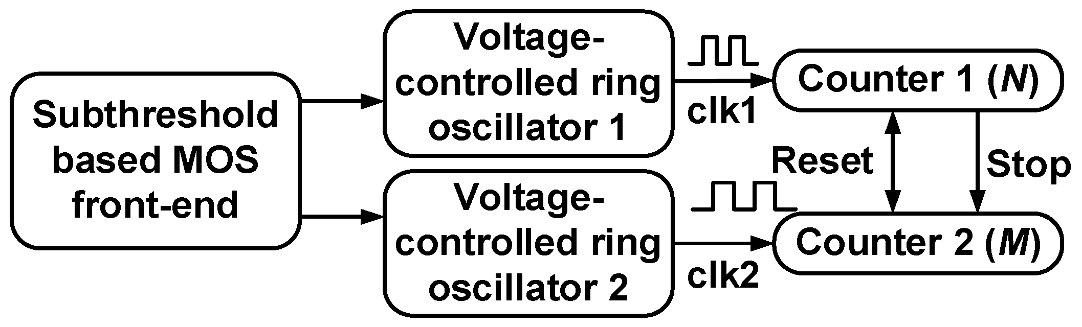
2.2. Subthreshold MOS-Based Temperature Sensor (Type II)

The temperature sensors described in the previous Section 2.1 make use of the MOSFETs working in their saturation and linear regions. In contrast, when a MOSFET is working its subthreshold region (when Vgs < VTH), its drain current can be expressed by [16,17]
I s u b = μ C O X W L V T 2 e x p V g s V T H n V T 1 e x p V d s V T
where VTH, µ, W/L, COX are the threshold voltage, carrier mobility, width and length ratio and MOS oxide capacitance. VT is the thermal voltage kT/q. when Vds > 3VT, Equation (5) can be reduced to
I s u b = μ C O X W L V T 2 e x p V g s V T H n V T
Figure 7 illustrates the generation of PTAT voltage: when two MOSFETs M1 and M2 are working in their subthreshold regions with proportional current density, their drain current can be expressed as
μ C O X W L V T 2 e x p V g s , 1 V T H , 1 n V T = K · μ C O X m W L V T 2 e x p V g s , 2 V T H , 2 n V T
Then their gate-source voltage difference ΔVgs can be deduced to be
Δ V g s = V g s , 1 V g s , 2 = n V T ln m · K
where m∙K > 1, supposing no mismatches exist between M1 and M2′s VTH. Equation (8) is analogous to a BJT-based PTAT, despite it not being absolutely PTAT due to the influence from Vds, which was ignored in Equation (6). Another source that deviates Equation (8) from PTAT is n that is sensitive to process variations. Figure 8 shows the simulated ΔVgs vs. temperature, when m = 4, K = 2, using a 55 nm CMOS technology, indicating its PTAT characteristic is only valid over a limited temperature range. It is simulated for m = 4, K = 2, between −55 and 125 °C, for TT corner, using a 55 nm CMOS technology.
Publications [16,17,18] belong to this category of subthreshold MOS-based temperature sensors where the PTAT voltage similar to that shown in Equation (8) was converted into a PTAT current through a resistor with negligible thermal coefficient. In [16], the PTAT current was further converted into a CTAT delay through a capacitor, as tdis = CLVDD/Idis. In [17], the PTAT current was employed to control the ring oscillator, whose oscillation frequency becomes CTAT, which is in turn quantized by a following counter. Temperature sensors that rely on the subthreshold current-controlled ring oscillator are presented in [19,20,21,22,28]. To get rid of the need for a frequency reference, the ratio of the oscillation frequencies between two current-starved ring oscillators/delay cells working in the subthreshold region is obtained as a digital representation of temperature [24,25,26,27], where the two ring oscillators are either controlled with proportional currents or devices with different VTH.
In reference [29,30,31], a PTAT voltage similar to that expressed in Equation (8) and shown in Figure 7, is further quantized by the following delta-sigma ADCs, hence achieving better resolution and accuracy [30,31], or a wider temperature range [29]. In [30,31], the body and gate of the nMOS pair (as shown in Figure 7) are connected together, so that they work as a diode and the pair functions analogously to a BJT-based PTAT precision temperature sensor.

2.3. Gate Leakage-Based Temperature Sensors (Type III)

In 2017, a gate leakage-based temperature sensor was presented at CICC [32]. The temperature sensor stacked a MOSFET between the power supply and the current-starved ring oscillator. The MOSFET’s gate was connected to the power supply. Its drain, source and body were connected together, as node S, which was connected to the ring oscillator’s supply node. In this way, the MOSFET’s gate leakage current controlled the oscillation frequency of the ring oscillator. One obvious advantage of the gate leakage-based temperature sensor proposed in [32] was its energy efficiency, which was seven times better than the state-of-the-art works at its time of publication, as its sensing front-end was based on the gate leakage current, and consumed only 640 pW. Reference [33] relies on both thermal dependent gate-leakage current and subthreshold MOSFETs but is classified into this category due to its power efficiency.

3. Design Considerations and Challenges for the MOS-Based Temperature Sensors

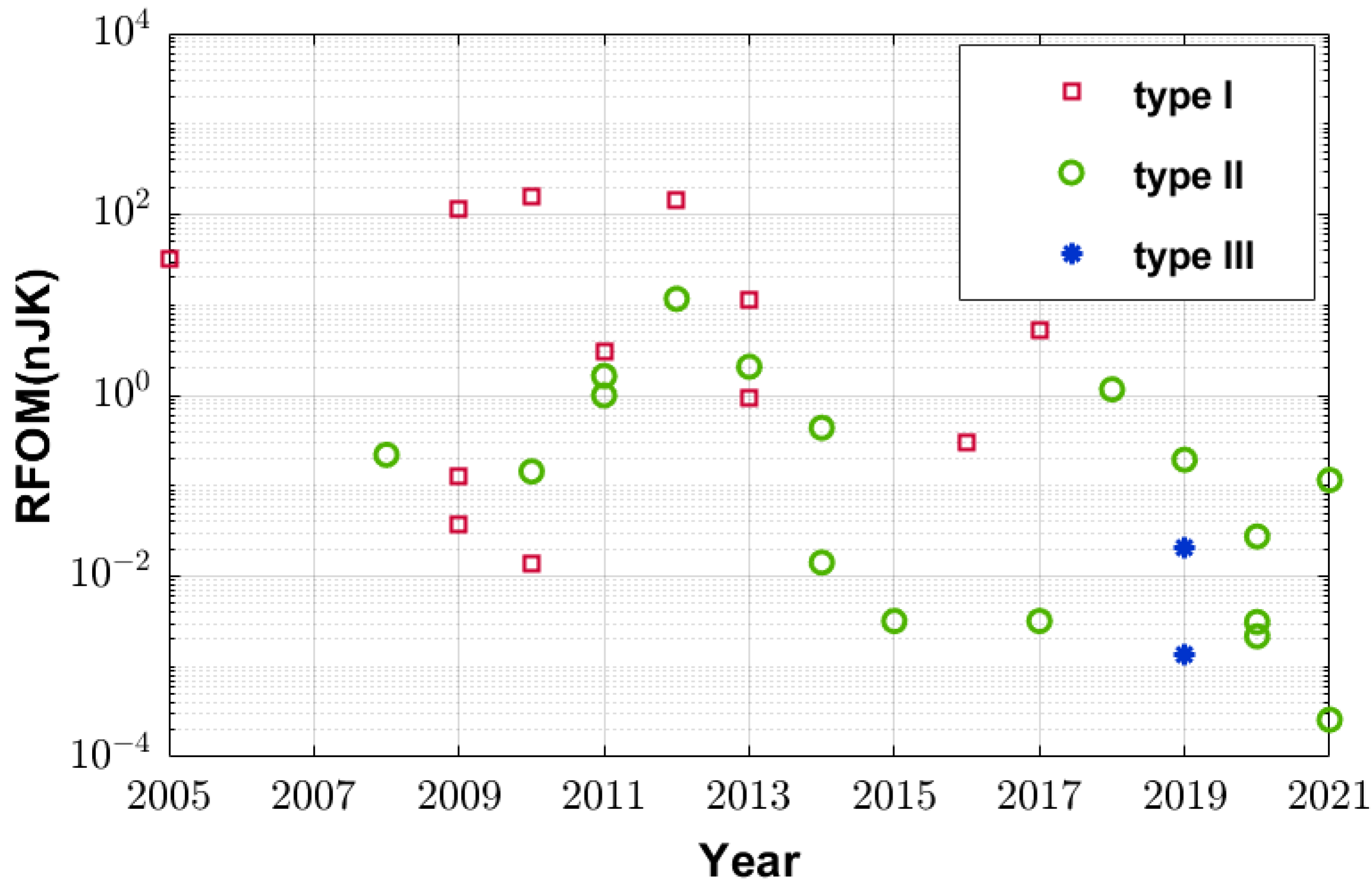
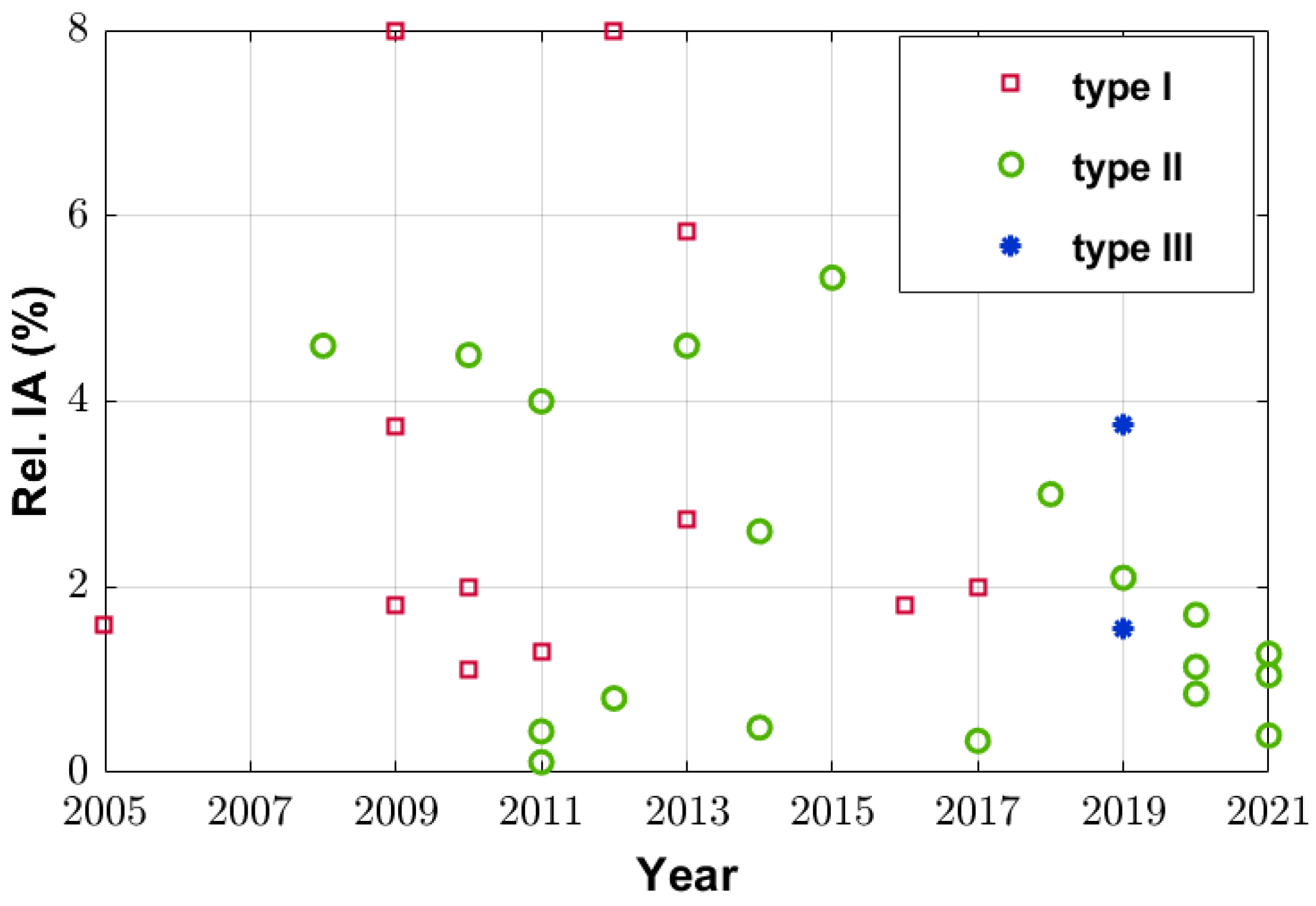
3.1. The Type of Choice Versus Year of Publication
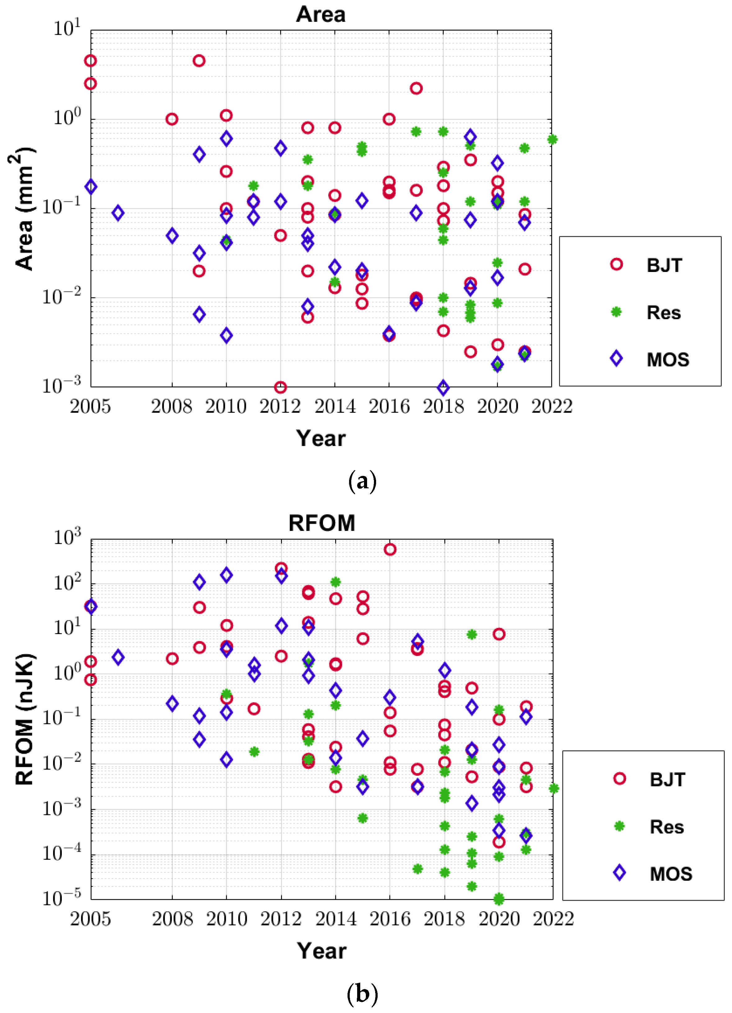
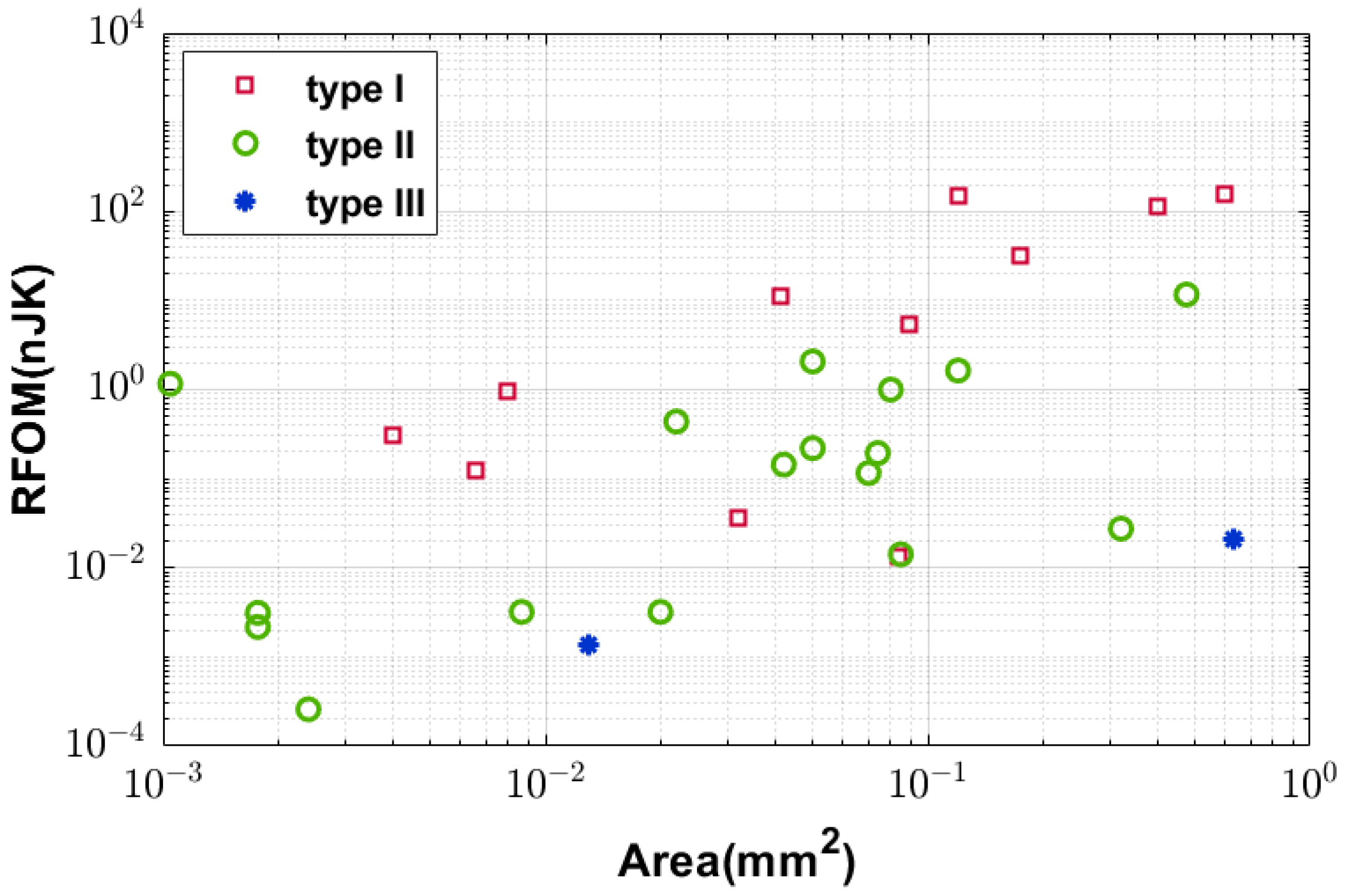
Figure 9 shows the aforementioned three types’ areas versus the year of publication. From the figure, one can observe that type II, the subthreshold MOS-based temperature sensors, have gained popularity over the last 5 years. The reasons for this trend will be explained in the next subsection.

3.2. Area

The areas for the three types of temperature sensors are plotted in Figure 9. It can be seen from Figure 9 that the smallest three sensors belong to type II, the subthreshold types. One of the possible reasons is that for type I, logic or saturation MOS-based temperature sensors, a larger portion of the delay is unused for thermal sensing. A case in point is when comparing Figure 5 and Figure 8, only approximately 0.6% of the propagation delay of the logic inverter (type I) shown in Figure 5, is thermal dependent, while the rest is thermal independent. In contrast, in Figure 8, for the subthreshold-based type II, around 22% of the delay depends on temperature. In other words, for a similar resolution, the total delay lines for type I have to be longer than those for type II. Another reason, which also explains why the second type becomes more popular, is as the power supply level decreases with the technology node, the thermal coefficient for type I’s delay becomes smaller, as simulated in Figure 5. Another observation that can be made from Figure 9 is that the gate leakage-based type III is less area efficient, compared with the other two alternatives. The reason is the gate leakage current is normally smaller, and therefore requires either a larger sensing device or a more carefully designed quantizer, which, in turn, requires area.

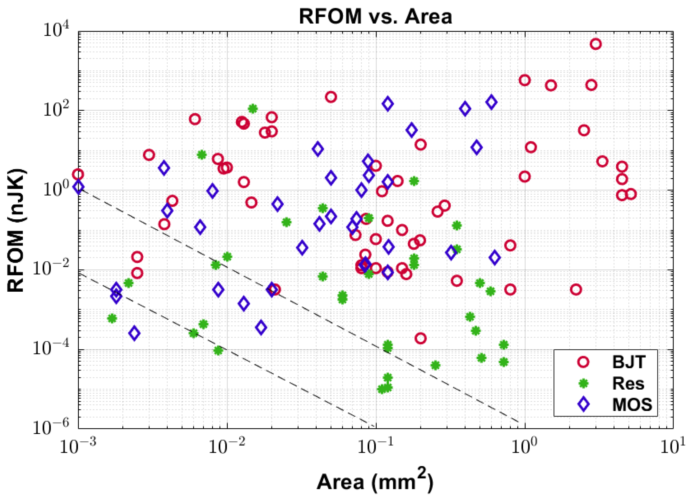
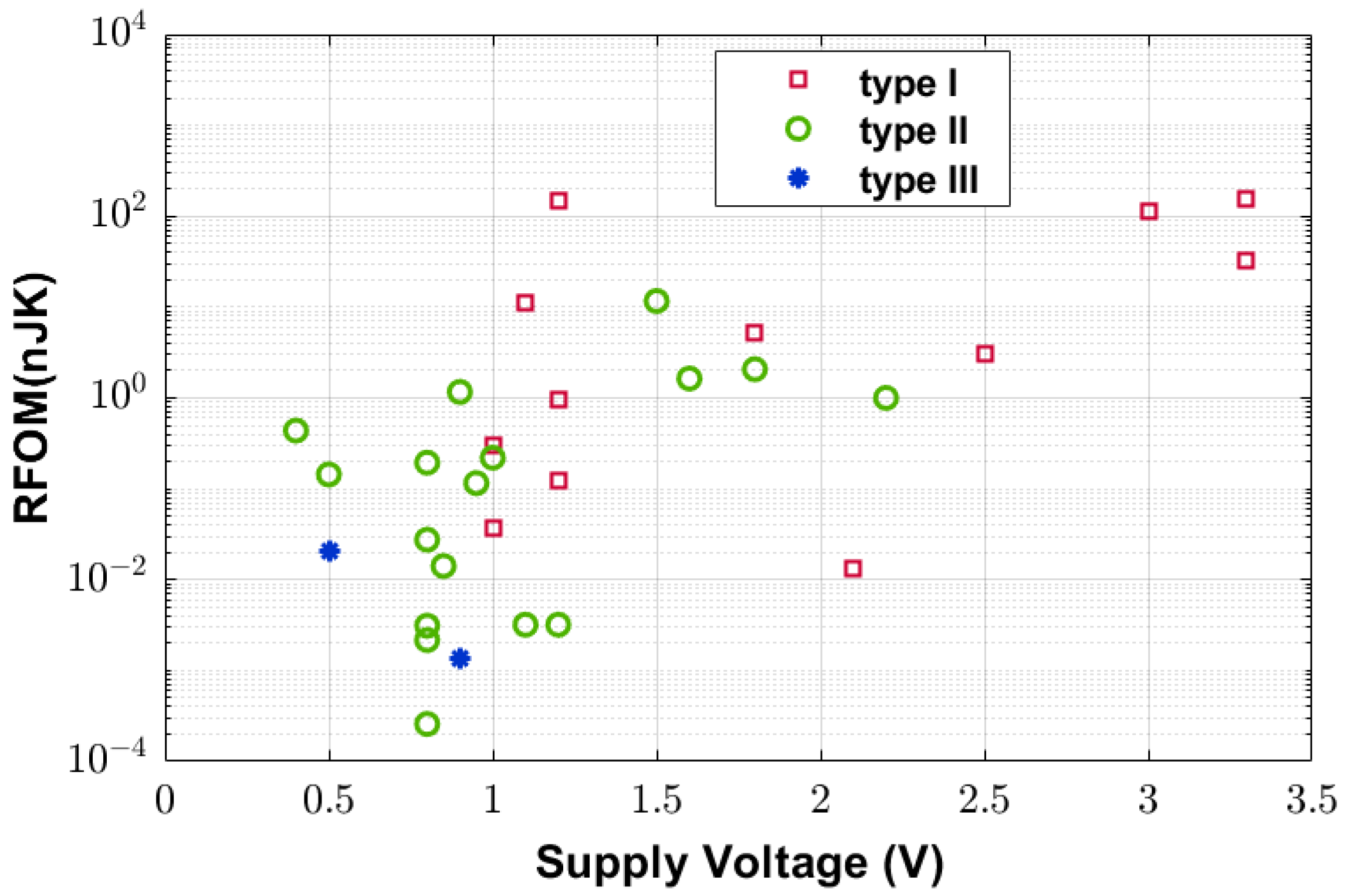
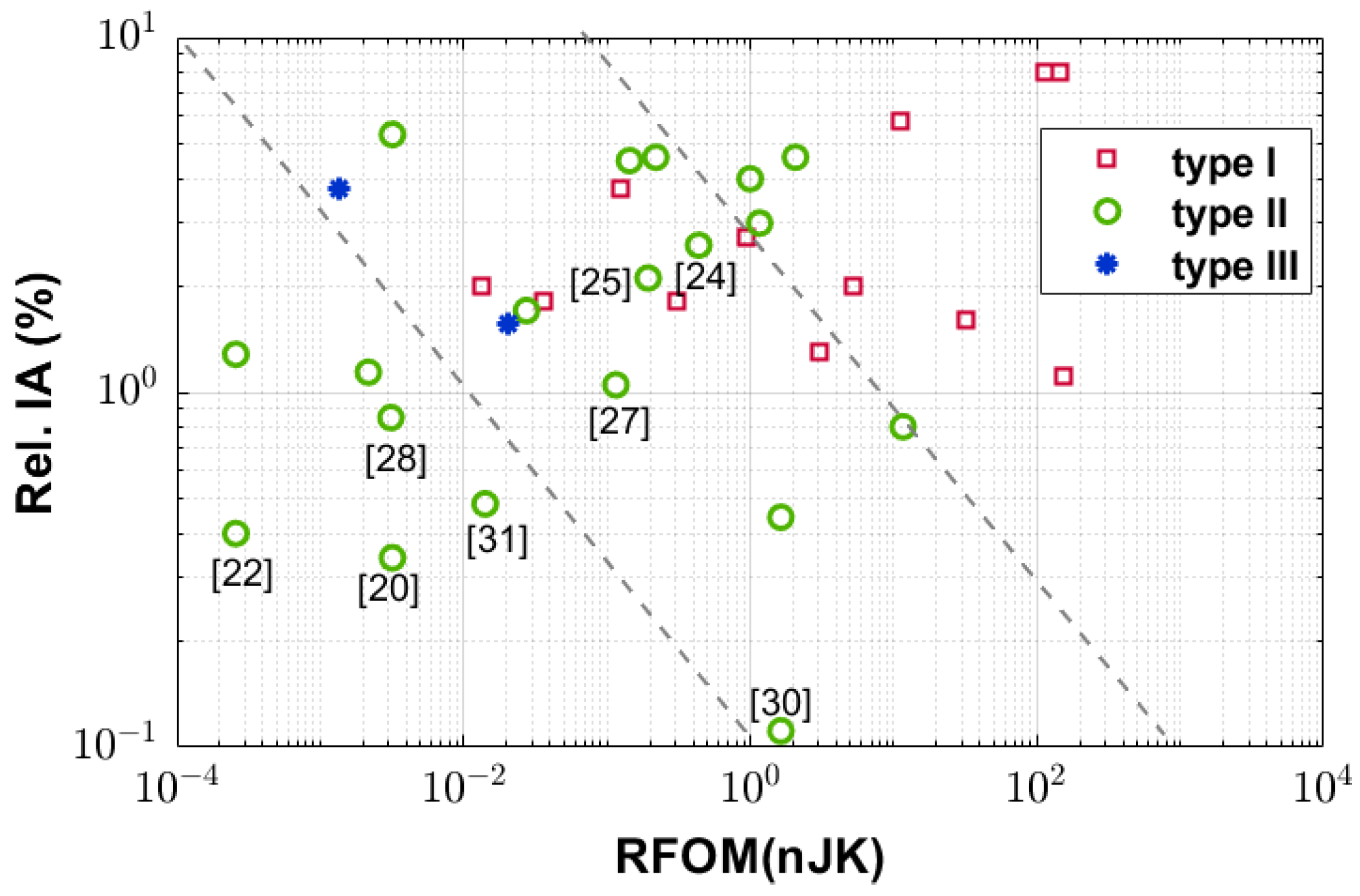
3.3. The Resolution Figure of Merit (RFOM) Versus Area

The resolution figure of merit (RFOM) is calculated as the energy/conversion∙resolution2 and is a measure of energy efficiency in reference to its resolution. The RFOM versus the year of publication and the area are plotted in Figure 10 and Figure 11, respectively, for all three types. From Figure 10, one can observe that the RFOM is declining over the years and the type II sensors are among those with the smallest RFOM. A few observations can also be made from Figure 11, as follows: (1) The general trend is the RFOM increases with area, for all three types; (2) For most cases, for the same design area, type I has the larger RFOM than type II and type III, which indicates that type I has a worse energy efficiency, in general.
When a designer targets a lower RFOM or better energy efficiency, one should consider using a smaller number of devices or smaller sized circuit components, given it meets other design requirements. To some degree, this is understandable, as J = CV2, therefore, the smaller the C (the total loading capacitance), the lower the energy consumption.

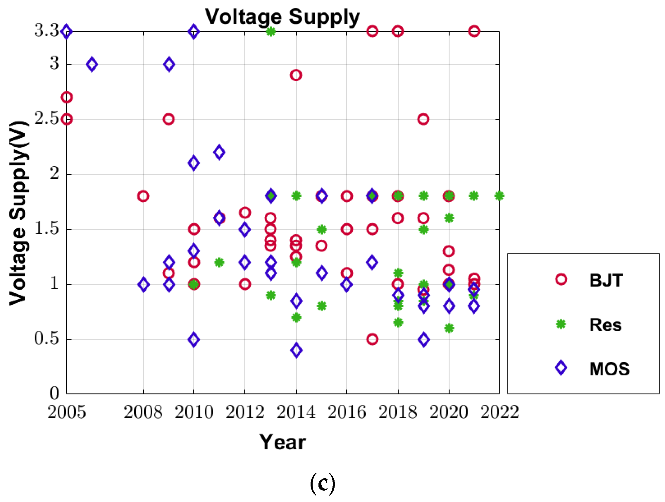
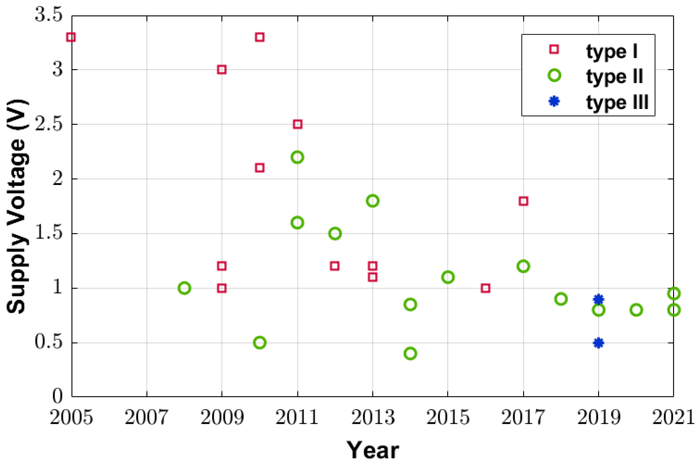
3.4. The Supply Voltage

Figure 12 shows the supply voltage level versus the year of publication. It indicates that, in general, the supply voltages for type II have been declining, during the last 10 years. It would be intuitive that RFOM are highly correlated with the supply voltage, as mentioned in the previous subsection, J = CV2, as plotted in Figure 13. Another observation that could be made from Figure 13 is that the subthreshold MOS-based temperature sensor’s RFOM has a stronger correlation with the supply voltage, compared to type I, in general. In other words, the type II’s RFOM benefits more from voltage scaling.

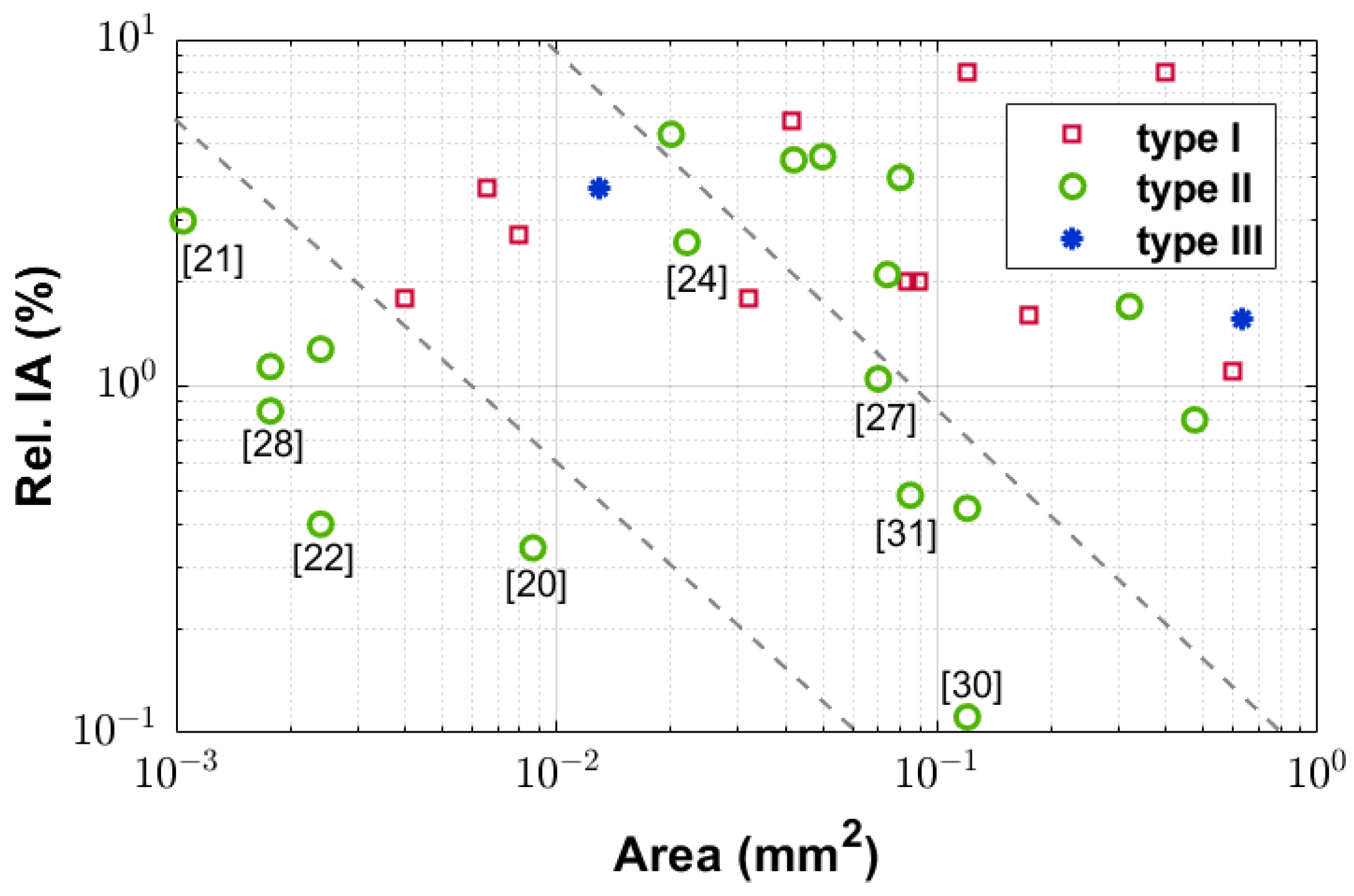
3.5. Inaccuracy vs. Area and Energy Efficiency

The relative inaccuracy (Rel. IA) was defined as 100×PP_IA/specified temperature range [106] where PP_IA is the worst-case inaccuracy (IA) over a specified temperature range. The Rel. IA for all three types is plotted against the year of publication in Figure 14, from which one can observe that the relative inaccuracy of the type II sensor has been getting better for the last 5 years. Figure 15 and Figure 16 show the Rel. IA versus the area and the RFOM, respectively, along with the constant product lines for the x and y axes for both figures. They indicate: (1) Among those sensors that have better trade-offs (or the smallest Rel. IA and area products, as well as Rel. IA and RFOM products) are references [20,22,28], which are all type II sensors. In Figure 14, the reference number is labelled next to the marker for type II. Those markers without any label either belong to the same publication but have a different trimming method, or, their inaccuracies are too high; (2) Other type II sensors, such as [24,27,30,31], also have relatively better trade-offs among area, power and accuracy, compared to the rest of the surveyed MOS-based temperature sensors. Among all the aforementioned references in this subsection, [20,22] rely on the subthreshold current-controlled ring oscillators’ temperature coefficient; the authors of [24,27,28] obtain the oscillation frequency ratio between two temperature-dependent ring oscillators either biased with proportional currents or with different VTH levels. References [30,31] quantize their PTAT voltage front-end using voltage-domain delta-sigma ADCs. Among them, references [22,24,27,28,31] are powered by sub-1V (below 1V) power supplies. Therefore, the next subsection, Section 3.6 will focus on these five publications.

3.6. Process Variations, Number of Trims and Global Curve Fitting

This subsection focuses on the sub-1V designs that have better trade-offs among area, power and accuracy, mentioned in the last Section 3.5, namely, references [22,24,27,28,31], among which, [31] achieves a 3σ inaccuracy of ±0.4 °C, over the temperature range of −45 and 125 °C, with a one-point trim, while the rest of the references, [22,24,27,28] require at least two-point calibrations to achieve inaccuracies below ±0.5 °C, for their temperature ranges shown in Figure 17. The process variation is the reason. To mitigate the process variations, dynamic element matching (DEM) is employed in [31], along with a linearity calibration for each on-chip zoom ADC that quantizes the sensor’s PTAT front-end. In contrast, in [22,24,27,28] the temperature sensors work in the time domain and no DEM similar to that in [31] can be employed.
To better understand the effect of process variations on the temperature sensors, the block diagram showing the operating principle of the subthreshold MOS-based (type II) sensors [24,25,26,27] is drawn in Figure 18. The current-controlled oscillator may also be replaced by another type of delay cell [24]. The reference line, oscillator 1, is introduced for two purposes: to serve as the clock reference for oscillator 2 and to further remove the power supply sensitivity.
For the temperature sensor shown in Figure 18, the delay of oscillator 1 or 2 can be expressed as tdis = CLVDD/Idis. As the oscillator’s frequency is f = 1/(tdis + tcha), which is the inverse of the sum of the discharging time for nMOS and the charging time for pMOS. Assuming VDD is identical for both oscillators at this moment, their current and oscillation frequency ratio can be obtained from Equation (5) as
f o s c , 1 f o s c , 2 = I s u b , 1 I s u b , 2 = e x p V g s , 1 V T H , 1 V g s , 2 + V T H , 2 n V T
fosc,1 and fosc,2 refer to the oscillation frequency for oscillator 1 and 2, respectively. The thermal coefficient of I s u b , 1 I s u b , 2 can be obtained from the voltage difference either between Vgs,1 and Vgs,2, which is linked to series diode-connected bias [24], or between VTH,1 and VTH,2 voltage levels [27]. For a limited temperature range, Equation (9) can be quite linear [24,27] and can be obtained from counter 2′s outputs M in practical implementation, as
f o s c , 1 f o s c , 2 = I s u b , 1 I s u b , 2 = M N
which indicates that when counter 1 counts 1 N numbers, which is a fixed number and it sends a stop/latch signal to counter 2, whose output M is the final digital representation of temperature.
When one applies the ln function to both sides of Equation (9), one gets
ln I s u b , 1 I s u b , 2 = V g s , 1 V T H , 1 V g s , 2 + V T H , 2 n V T
where VT is the thermal voltage kT/q, and supposing Vgs,1 = Vgs,2 and VTH,1 = β1 − α1T and VTH,2 = β2 − α2T; α1 ≠ α2; β1β2. Equation (11) can be expressed as a function of T
ln M N = ln I s u b , 1 I s u b , 2 = q n k α 1 α 2 + β 2 β 1 T
where n, α1, α2, β1, β2 are all process dependent factors. Equation (12) indicates that the final digital representations of temperatures,   M N , contain an offset and a gain factor, respectively, and both are sensitive to process variations. Therefore, to remove the offset and the gain at the same time, the temperature sensors have to be calibrated at two temperature points (e.g., −25 and 100 °C), at least. In other words, if a temperature sensor having the characteristic as shown in Equation (12) is only calibrated at one point, either the gain or the offset can be removed, and therefore resulting in larger inaccuracies than when calibrated at two points, for the same sensor, as shown in Figure 17.
The one-point calibration concept was first proposed for the type I, logic and saturation MOS-based temperature sensor [4]. However, it may only be valid when the power supply level VDD is much larger than VTH, e.g., VDD ≥ 1.1 V, as the basis for the one-point calibration proposed in [4] is to consider the carrier mobility µ for thermal dependency while neglecting that for VTH, as expressed in Equation (1). In other words, as VDD drops, the thermal dependency from VTH cannot be ignored. Even when VDD is larger than 1.1 V, e.g., 1.2 V in [4], the errors of ±4 °C after its one-point calibration are much larger than using a two-point calibration alternative. Nevertheless, the advantage of the one-point calibration is the reduction in high volume production costs. This advantage is meaningful for microprocessor thermal management, where lower calibration cost is desired and an inaccuracy of ±5 °C is acceptable.
After either a one-point or a two-point calibration that removes the process variations between different temperature sensors on the same or on different chips, a global master curve is applied to convert the digital outputs of each sensor into the temperatures. This master curve can be of third [4,28] or lower orders. In [28], the third order master curve, or, systematic error correction, is implemented off-chip. For mass production, a second or third master curve would mean extra cost and complexity and it is desirable that the master curve can be linear, or, of first order. In other words, the less inaccuracy between the sensor and the global linear master curve fitting, the better for mass production.

3.7. Noise

A sensor’s noise limits its resolution [12]. The noise, or the measurement uncertainties in the temperature sensor outputs are shown in [34], which also indicates when the conversion time is increased from 4 ms to 16 ms, the measured uncertainty-induced errors reduce from ±3 °C to ±1 °C. It is believed in [34] that the high frequency noise can be averaged out using a longer conversion time. In [27], the jitter or phase noise induced error is demonstrated to be proportional to its resolution (LSB) and is inversely proportional to a single cell’s propagation delay. When the ring oscillator or VCO’s delay line is long enough, or, when the sensor’s resolution is fine enough, the phase noise induced error can be kept small, e.g., around 0.02 °C in [27].

3.8. Power Supply Sensitivity

The power supply sensitivities of the temperature sensors [22,26,27,28,33] are listed in Table 1, along with other performance parameters. For MOS-based temperature sensors working in their subthreshold regions, when their supply voltage level changes, the subthreshold current level deviates, as expressed in Equation (5), which is a function of Vds, affected by the supply voltage level VDD [27]. Similarly, when VDD changes, the saturation current in Equation (3) changes, so does the propagation delay in Equation (1). When the supply voltage changes dynamically, the charging and discharging currents in the MOSFETs change accordingly and give rise to either increased or decreased propagation delay or oscillation frequency. This (rise or drop in the delay or the frequency) will eventually change the temperature sensors’ output readings (digital numbers) dynamically, as illustrated in Figure 19a, where the output codes rise 30 digital numbers (DN) within a 0.7 s interval, and the sensor mistakenly gives an information of −26 °C temperature change (at around 400 s), when the power supply changes suddenly [109]. Almost all types of temperature sensors, including the MOS-based ones, are sensitive to power supply level change. Currently, the methods to reduce the power supply sensitivities of the MOS-based temperature sensors are as follows: the first is to use a voltage regulator, as described in [9,20,21]; the second is to employ two oscillators which reduce the supply sensitivities by their oscillation frequency ratio [12,24,26,27]; the third is the subthreshold leakage-based delay cell proposed in [28], whose principle of reducing supply sensitivity is as follows. The power supply sensitivity of the propagation delay in the particular cell is a function of the voltage swing for charging. By adjusting the voltage swing, the supply sensitivity can be minimized for the delay cell. It is mentioned in [28] that this minimum supply sensitivity voltage swing shifts for different chips, due to process variations, but can be kept within a reasonable range, despite the process and temperature variations. The linear-region MOS-based temperature [15] is claimed to reduce power supply sensitivity despite no exact number of supply sensitivity being mentioned.

3.9. Self-Heating and Lifespan

The thermal resistance of silicon is around 14 °C/W, which means the temperature can rise by 14 °C from ambient when its power dissipation is 1 W. For the selected MOS-based temperature sensors in this review, the maximum power reported is 1200 µW (reference [4]), and accordingly, the temperature rise (from ambient) is 0.0168 °C (=14 × 1200 µW/1,000,000), which is 40× smaller than its resolution, 0.78 °C. For most MOS-based sensors listed in Table 1, their power dissipations are below 10 µW, and their self-heatings are less than 0.14 mK, which is almost 100× smaller, compared to the finest resolution of 13 mK in reference [28]. Therefore, the self-heating effect is negligible for the MOS-based temperature sensors.
A typical temperature sensor in industry is designed, e.g., to operate for 10 years at 105 °C, and in general, the higher the junction temperature, the shorter the lifespan of the temperature sensor.

4. Conclusions

This paper reviews the MOS-based temperature sensors and categorize them into three types: type I, the logic, saturation and linear MOS-based temperature sensors; type II, the subthreshold MOS-based temperature sensors; and type III, the gate leakage-based temperature sensors. In addition, it discusses the design considerations and challenges for the MOS-based temperature sensors, including: area, energy efficiency, accuracy, process variations, noise and power supply sensitivity. The future MOS-based temperature sensors may be based on the subthreshold MOSFET operation, which is the most popular design type among the three, currently. It should have better trade-offs between area, power efficiency and accuracy, likely having a differential architecture that reduces its power supply sensitivity, along with a lower-cost (e.g., one-point or self-calibrated) calibration method, powered at a supply voltage under 1 V.

Funding

This work has been funded by the School of Microelectronics start-up funding, Shandong University, Grant Number: 11500061510000.

Data Availability Statement

The datasets generated during and/or analyzed during the current study are not publicly available due to it still being unpublished but are available from the corresponding author on reasonable request.

Acknowledgments

The authors would like to thank Y. Wang’s group for their technical support. We would like to thank all the editors and reviewers for their valuable comments.

Conflicts of Interest

The authors declare no conflict of interest.

References

  1. Kazys, R.; Vaskeliene, V. High Temperature Ultrasonic Transducers: A Review. Sensors 2021, 21, 3200. [Google Scholar] [CrossRef] [PubMed]
  2. Sheikh, H.F.; Ahmad, I.; Wang, Z.; Ranka, S. An overview and classification of thermal-aware scheduling techniques for multi-core processing systems. Sustain. Comput. Inform. Syst. 2012, 2, 151–169. [Google Scholar] [CrossRef]
  3. Aiello, O.; Fiori, F. On the Susceptibility of Embedded Thermal Shutdown Circuit to Radio Frequency Interference. IEEE Trans. Electromagn. Compat. 2012, 54, 405–412. [Google Scholar] [CrossRef]
  4. Ha, D.; Woo, K.; Meninger, S.; Xanthopoulos, T.; Crain, E.; Ham, D. Time-Domain CMOS Temperature Sensors with Dual Delay-Locked Loops for Microprocessor Thermal Monitoring. IEEE Trans. Very Large Scale Integr. (VLSI) Syst. 2012, 20, 1590–1601. [Google Scholar] [CrossRef]
  5. Chen, P.; Chen, S.; Shen, Y.; Peng, Y. All-Digital Time-Domain Smart Temperature Sensor with an Inter-Batch Inaccuracy of −0.7 °C–+0.6 °C After One-Point Calibration. IEEE Trans. Circuits Syst. I Regul. Pap. 2011, 58, 913–920. [Google Scholar] [CrossRef]
  6. Chen, P.; Chen, C.; Peng, Y.; Wang, K.; Wang, Y. A Time-Domain SAR Smart Temperature Sensor with Curvature Compensation and a 3σ Inaccuracy of −0.4 °C ∼ +0.6 °C Over a 0 °C to 90 °C Range. IEEE J. Solid-State Circuits 2010, 45, 600–609. [Google Scholar] [CrossRef]
  7. Chen, P.; Chen, T.-K.; Wang, Y.-S.; Chen, C.-C. A Time-Domain Sub-Micro Watt Temperature Sensor with Digital Set-Point Programming. IEEE Sens. J. 2009, 9, 1639–1646. [Google Scholar] [CrossRef]
  8. Chen, P.; Chen, C.; Tsai, C.; Lu, W. A time-to-digital-converter-based CMOS smart temperature sensor. IEEE J. Solid-State Circuits 2005, 40, 1642–1648. [Google Scholar] [CrossRef]
  9. Hwang, S.; Koo, J.; Kim, K.; Lee, H.; Kim, C. A 0.008 mm2 500/spl mu/W 469 kS/s Frequency-to-Digital Converter Based CMOS Temperature Sensor with Process Variation Compensation. IEEE Trans. Circuits Syst. I Regul. Pap. 2013, 60, 2241–2248. [Google Scholar] [CrossRef]
  10. Kim, K.; Lee, H.; Jung, S.; Kim, C. A 366 kS/s 400 uW 0.0013 mm2 frequency-to-digital converter based CMOS temperature sensor utilizing multiphase clock. In Proceedings of the 2009 IEEE Custom Integrated Circuits Conference, San Jose, CA, USA, 13–16 September 2009; pp. 203–206. [Google Scholar] [CrossRef]
  11. Vaz, A.; Ubarretxena, A.; Zalbide, I.; Pardo, D.; Solar, H.; Garcia-Alonso, A.; Berenguer, R. Full Passive UHF Tag with a Temperature Sensor Suitable for Human Body Temperature Monitoring. IEEE Trans. Circuits Syst. II Express Briefs 2010, 57, 95–99. [Google Scholar] [CrossRef]
  12. Anand, T.; Makinwa, K.A.A.; Hanumolu, P.K. A self-referenced VCO-based temperature sensor with 0.034 °C/mV supply sensitivity in 65 nm CMOS. In Proceedings of the 2015 Symposium on VLSI Circuits (VLSI Circuits), Kyoto, Japan, 17–19 June 2015; pp. C200–C201. [Google Scholar] [CrossRef]
  13. Shim, D.; Jeong, H.; Lee, H.; Rhee, C.; Jeong, D.-K.; Kim, S. A Process-Variation-Tolerant on-Chip CMOS Thermometer for Auto Temperature Compensated Self-Refresh of Low-Power Mobile DRAM. IEEE J. Solid-State Circuits 2013, 48, 2550–2557. [Google Scholar] [CrossRef]
  14. Song, W.; Lee, J.; Cho, N.; Burm, J. An Ultralow Power Time-Domain Temperature Sensor with Time-Domain Delta–Sigma TDC. IEEE Trans. Circuits Syst. II Express Briefs 2017, 64, 1117–1121. [Google Scholar] [CrossRef]
  15. Law, M.K.; Bermak, A. A 405-nW CMOS Temperature Sensor Based on Linear MOS Operation. IEEE Trans. Circuits Syst. II Express Briefs 2009, 56, 891–895. [Google Scholar] [CrossRef] [Green Version]
  16. Law, M.K.; Bermak, A.; Luong, H.C. A Sub-µ W Embedded CMOS Temperature Sensor for RFID Food Monitoring Application. IEEE J. Solid-State Circuits 2010, 45, 1246–1255. [Google Scholar] [CrossRef]
  17. Lin, Y.; Sylvester, D.; Blaauw, D. An ultra low power 1 V, 220 nW temperature sensor for passive wireless applications. In Proceedings of the 2008 IEEE Custom Integrated Circuits Conference, San Jose, CA, USA, 21–24 September 2008; pp. 507–510. [Google Scholar] [CrossRef]
  18. Ueno, K.; Asai, T.; Amemiya, Y. Low-power temperature-to-frequency converter consisting of subthreshold CMOS circuits for integrated smart temperature sensors. Sens. Actuators A Phys. 2011, 165, 132–137. [Google Scholar] [CrossRef]
  19. Kim, Y.; Choi, W.; Kim, J.; Lee, S.; Lee, S.; Kim, H.; Makinwa, K.A.A.; Chae, Y.; Kim, T.W. A 0.02 mm2 embedded temperature sensor with ±2 °C inaccuracy for self-refresh control in 25 nm mobile DRAM. In Proceedings of the ESSCIRC Conference 2015—41st European Solid-State Circuits Conference (ESSCIRC), Graz, Austria, 14–18 September 2015; pp. 267–270. [Google Scholar] [CrossRef]
  20. Yang, K.; Dong, Q.; Jung, W.; Zhang, Y.; Choi, M.; Blaauw, D.; Sylvester, D. 9.2 A 0.6 nJ −0.22/+0.19 °C inaccuracy temperature sensor using exponential subthreshold oscillation dependence. In Proceedings of the 2017 IEEE International Solid-State Circuits Conference (ISSCC), San Francisco, CA, USA, 5–9 February 2017; pp. 160–161. [Google Scholar] [CrossRef]
  21. Cochet, M.; Keller, B.; Clerc, S.; Abouzeid, F.; Cathelin, A.; Autran, J.; Roche, P.; Nikolić, B. A 225 μm2 Probe Single-Point Calibration Digital Temperature Sensor Using Body-Bias Adjustment in 28 nm FD-SOI CMOS. IEEE Solid-State Circuits Lett. 2018, 1, 14–17. [Google Scholar] [CrossRef]
  22. Tang, Z.; Huang, Z.; Yu, X.-P.; Shi, Z.; Tan, N.N. A 0.26-pJ·K2 2400-μm2 Digital Temperature Sensor in 55-nm CMOS. IEEE Solid-State Circuits Lett. 2021, 4, 96–99. [Google Scholar] [CrossRef]
  23. Fojtik, M.; Kim, D.; Chen, G.; Lin, Y.; Fick, D.; Park, J.; Seok, M.; Chen, M.; Foo, Z.; Blaauw, D.; et al. A Millimeter-Scale Energy-Autonomous Sensor System with Stacked Battery and Solar Cells. IEEE J. Solid-State Circuits 2013, 48, 801–813. [Google Scholar] [CrossRef]
  24. Zhao, W.; Pan, R.; Ha, Y.; Yang, Z. A 0.4 V 280-nW frequency reference-less nearly all-digital hybrid domain temperature sensor. In Proceedings of the 2014 IEEE Asian Solid-State Circuits Conference (A-SSCC), KaoHsiung, Taiwan, 10–12 November 2014; pp. 301–304. [Google Scholar] [CrossRef]
  25. Someya, T.; Islam, A.K.M.M.; Sakurai, T.; Takamiya, M. An 11-nW CMOS Temperature-to-Digital Converter Utilizing Subthreshold Current at Sub-Thermal Drain Voltage. IEEE J. Solid-State Circuits 2019, 54, 613–622. [Google Scholar] [CrossRef]
  26. Someya, T.; Islam, A.K.M.M.; Okada, K. A 6.4 nW 1.7% Relative Inaccuracy CMOS Temperature Sensor Utilizing Sub-Thermal Drain Voltage Stabilization and Frequency-Locked Loop. IEEE Solid-State Circuits Lett. 2020, 3, 458–461. [Google Scholar] [CrossRef]
  27. Li, J.; Lin, Y.; Ning, N.; Yu, Q. A +0.44 °C/−0.4 °C Inaccuracy Temperature Sensor with Multi-Threshold MOSFET-Based Sensing Element and CMOS Thyristor-Based VCO. IEEE Trans. Circuits Syst. I Regul. Pap. 2021, 68, 1102–1113. [Google Scholar] [CrossRef]
  28. Tang, Z.; Fang, Y.; Shi, Z.; Yu, X.-P.; Tan, N.N.; Pan, W. A 1770-µm2 Leakage-Based Digital Temperature Sensor with Supply Sensitivity Suppression in 55-nm CMOS. IEEE J. Solid-State Circuits 2020, 55, 781–793. [Google Scholar] [CrossRef]
  29. Lee, S.-C.; Chiueh, H. A 69 μW CMOS smart temperature sensor with an inaccuracy of ±0.8 °C (3σ) from −50 °C to 150 °C. SENSORS 2012, 2012, 6411595. [Google Scholar] [CrossRef]
  30. Souri, K.; Chae, Y.; Ponomarev, Y.; Makinwa, K.A.A. A precision DTMOST-based temperature sensor. In Proceedings of the ESSCIRC (ESSCIRC), Helsinki, Finland, 12–16 September 2011; pp. 279–282. [Google Scholar] [CrossRef]
  31. Souri, K.; Chae, Y.; Thus, F.; Makinwa, K. 12.7 A 0.85 V 600 nW all-CMOS temperature sensor with an inaccuracy of ±0.4 °C (3σ) from −40 to 125 °C. In Proceedings of the 2014 IEEE International Solid-State Circuits Conference Digest of Technical Papers (ISSCC), San Francisco, CA, USA, 9–13 February 2014; pp. 222–223. [Google Scholar] [CrossRef]
  32. Truesdell, D.S.; Calhoun, B.H. A 640 pW 22 pJ/sample Gate Leakage-Based Digital CMOS Temperature Sensor with 0.25 °C Resolution. In Proceedings of the 2019 IEEE Custom Integrated Circuits Conference (CICC), Austin, TX, USA, 14–17 April 2019; pp. 1–4. [Google Scholar] [CrossRef]
  33. Wang, H.; Mercier, P.P. A 763 pW 230 pJ/Conversion Fully Integrated CMOS Temperature-to-Digital Converter with +0.81 °C/−0.75 °C Inaccuracy. IEEE J. Solid-State Circuits 2019, 54, 2281–2290. [Google Scholar] [CrossRef]
  34. Jeong, S.; Foo, Z.; Lee, Y.; Sim, J.; Blaauw, D.; Sylvester, D. A Fully-Integrated 71 nW CMOS Temperature Sensor for Low Power Wireless Sensor Nodes. IEEE J. Solid-State Circuits 2014, 49, 1682–1693. [Google Scholar] [CrossRef]
  35. Pertijs, M.A.P.; Niederkorn, A.; Ma, X.; McKillop, B.; Bakker, A.; Huijsing, J.H. A CMOS smart temperature sensor with a 3/spl sigma/ inaccuracy of /spl plusmn/0.5/spl deg/C from −50/spl deg/C to 120/spl deg/C. IEEE J. Solid-State Circuits 2005, 40, 454–461. [Google Scholar] [CrossRef]
  36. Pertijs, M.; Makinwa, K.; Huijsing, J. A CMOS temperature sensor with a 3/spl sigma/ inaccuracy of /spl plusmn/0.1/spl deg/C from −55/spl deg/C to 125/spl deg/C. In Proceedings of the ISSCC—2005 IEEE International Digest of Technical Papers. Solid-State Circuits Conference, San Francisco, CA, USA, 10 February 2005; Volume 1, pp. 238–596. [Google Scholar] [CrossRef]
  37. Aita, A.L.; Pertijs, M.A.P.; Makinwa, K.A.A.; Huijsing, J.H. A CMOS smart temperature sensor with a batch-calibrated inaccuracy of ±0.25 °C (3σ) from −70 °C to 130 °C. In Proceedings of the 2009 IEEE International Solid-State Circuits Conference—Digest of Technical Papers, San Francisco, CA, USA, 8–12 February 2009; pp. 342–343. [Google Scholar] [CrossRef]
  38. Li, Y.W.; Lakdawala, H.; Raychowdhury, A.; Taylor, G.; Soumyanath, K. A 1.05 V 1.6 mW 0.45 °C 3σ-resolution ΔΣ-based temperature sensor with parasitic-resistance compensation in 32 nm CMOS. In Proceedings of the 2009 IEEE International Solid-State Circuits Conference—Digest of Technical Papers, San Francisco, CA, USA, 8–12 February 2009; pp. 340–341. [Google Scholar] [CrossRef]
  39. Duarte, D.; Zepeda, P.; Hsu, S.; Maheshwari, A.; Taylor, G. HVM performance validation and DFM techniques used in a 32 nm CMOS thermal sensor system. In Proceedings of the IEEE Custom Integrated Circuits Conference 2010, San Jose, CA, USA, 19–22 September 2010; pp. 1–4. [Google Scholar] [CrossRef]
  40. Souri, K.; Kashmiri, M.; Makinwa, K. A CMOS temperature sensor with an energy-efficient zoom ADC and an Inaccuracy of ±0.25 °C (3 s) from −40 °C to 125 °C. In Proceedings of the 2010 IEEE International Solid-State Circuits Conference—(ISSCC), San Francisco, CA, USA, 7–11 February 2010; pp. 310–311. [Google Scholar] [CrossRef]
  41. Yin, J.; Yi, J.; Law, M.K.; Ling, Y.; Lee, M.C.; Ng, K.P.; Gao, B.; Luong, H.C.; Bermak, A.; Chan, M.; et al. A system-on-chip EPC Gen-2 passive UHF RFID tag with embedded temperature sensor. In Proceedings of the 2010 IEEE International Solid-State Circuits Conference—(ISSCC), San Francisco, CA, USA, 7–11 February 2010; pp. 308–309. [Google Scholar] [CrossRef]
  42. Zjajo, A.; Barragan, M.J.; de Gyvez, J.P. Low-Power Die-Level Process Variation and Temperature Monitors for Yield Analysis and Optimization in Deep-Submicron CMOS. IEEE Trans. Instrum. Meas. 2012, 61, 2212–2221. [Google Scholar] [CrossRef] [Green Version]
  43. Chowdhury, G.; Hassibi, A. An On-Chip Temperature Sensor with a Self-Discharging Diode in 32-nm SOI CMOS. IEEE Trans. Circuits Syst. II Express Briefs 2012, 59, 568–572. [Google Scholar] [CrossRef]
  44. Souri, K.; Chae, Y.; Makinwa, K. A CMOS temperature sensor with a voltage-calibrated inaccuracy of ±0.15 °C (3σ) from −55 to 125 °C. In Proceedings of the 2012 IEEE International Solid-State Circuits Conference, San Francisco, CA, USA, 19–23 February 2012; pp. 208–210. [Google Scholar] [CrossRef]
  45. Shalmany, S.H.; Draxelmayr, D.; Makinwa, K.A.A. A micropower battery current sensor with ±0.03% (3σ) inaccuracy from −40 to +85 °C. In Proceedings of the 2013 IEEE International Solid-State Circuits Conference Digest of Technical Papers, San Francisco, CA, USA, 17–21 February 2013; pp. 386–387. [Google Scholar] [CrossRef]
  46. Pu, X.; Ash, M.; Nagaraj, K.; Park, J.; Vu, S.; Kimelman, P.; de la Haye, S. A +0.4 °C accurate high-speed remote junction temperature sensor with digital Beta correction and series-resistance cancellation in 65 nm CMOS. In Proceedings of the 2013 Symposium on VLSI Circuits, Kyoto, Japan, 12–14 June 2013; pp. C214–C215. [Google Scholar]
  47. Shor, J.; Luria, K.; Zilberman, D. Ratiometric BJT-based thermal sensor in 32 nm and 22 nm technologies. In Proceedings of the 2012 IEEE International Solid-State Circuits Conference, San Francisco, CA, USA, 19–23 February 2012; pp. 210–212. [Google Scholar] [CrossRef]
  48. Wang, B.; Law, M.; Bermak, A.; Luong, H.C. A Passive RFID Tag Embedded Temperature Sensor with Improved Process Spreads Immunity for a −30 °C to 60 °C Sensing Range. IEEE Trans. Circuits Syst. I Regul. Pap. 2014, 61, 337–346. [Google Scholar] [CrossRef]
  49. Heidary, A.; Wang, G.; Makinwa, K.; Meijer, G. 12.8 A BJT-based CMOS temperature sensor with a 3.6 pJ·K2-resolution FoM. In Proceedings of the 2014 IEEE International Solid-State Circuits Conference Digest of Technical Papers (ISSCC), San Francisco, CA, USA, 9–13 February 2014; pp. 224–225. [Google Scholar] [CrossRef]
  50. Ro’ee, E.; Ariel, C. Untrimmed Low-Power Thermal Sensor for SoC in 22 nm Digital Fabrication Technology. J. Low Power Electron. Appl. 2014, 4, 304–316. [Google Scholar] [CrossRef] [Green Version]
  51. Oshita, T.; Shor, J.; Duarte, D.E.; Kornfeld, A.; Zilberman, D. Compact BJT-Based Thermal Sensor for Processor Applications in a 14 nm tri-Gate CMOS Process. IEEE J. Solid-State Circuits 2015, 50, 799–807. [Google Scholar] [CrossRef]
  52. Chuang, M.-C.; Tai, C.-L.; Hsu, Y.-C.; Roth, A.; Soenen, E. A temperature sensor with a 3 sigma inaccuracy of ±2 °C without trimming from −50 °C to 150 °C in a 16 nm FinFET process. In Proceedings of the ESSCIRC Conference 2015—41st European Solid-State Circuits Conference (ESSCIRC), Graz, Austria, 14–18 September 2015; pp. 271–274. [Google Scholar] [CrossRef]
  53. Deng, C.; Sheng, Y.; Wang, S.; Hu, W.; Diao, S.; Qian, D. A CMOS Smart Temperature Sensor with Single-Point Calibration Method for Clinical Use. IEEE Trans. Circuits Syst. II Express Briefs 2016, 63, 136–140. [Google Scholar] [CrossRef]
  54. Eberlein, M.; Yahav, I. A 28 nm CMOS ultra-compact thermal sensor in current-mode technique. In Proceedings of the 2016 IEEE Symposium on VLSI Circuits (VLSI-Circuits), Honolulu, HI, USA, 15–17 June 2016; pp. 1–2. [Google Scholar] [CrossRef]
  55. Yousefzadeh, B.; Shalmany, S.H.; Makinwa, K. A BJT-based temperature-to-digital converter with ±60 mK (3σ) inaccuracy from −70 °C to 125 °C in 160 nm CMOS. In Proceedings of the 2016 IEEE Symposium on VLSI Circuits (VLSI-Circuits), Honolulu, HI, USA, 15–17 June 2016; pp. 1–2. [Google Scholar] [CrossRef]
  56. Shalmany, S.H.; Draxelmayr, D.; Makinwa, K. A ±36A integrated current-sensing system with 0.3% gain error and 400 µA offset from −55 °C to +85 °C. In Proceedings of the 2016 IEEE Symposium on VLSI Circuits (VLSI-Circuits), Honolulu, HI, USA, 15–17 June 2016; pp. 1–2. [Google Scholar] [CrossRef]
  57. Law, M.; Lu, S.; Wu, T.; Bermak, A.; Mak, P.; Martins, R.P. A 1.1 µW CMOS Smart Temperature Sensor with an Inaccuracy of ±0.2 °C (3σ) for Clinical Temperature Monitoring. IEEE Sens. J. 2016, 16, 2272–2281. [Google Scholar] [CrossRef]
  58. Wang, G.; Heidari, A.; Makinwa, K.A.A.; Meijer, G.C.M. An Accurate BJT-Based CMOS Temperature Sensor with Duty-Cycle-Modulated Output. IEEE Trans. Ind. Electron. 2017, 64, 1572–1580. [Google Scholar] [CrossRef] [Green Version]
  59. Hsu, Y.-C.; Tai, C.-L.; Chuang, M.-C.; Roth, A.; Soenen, E. 5.9 An 18.75 µW dynamic-distributing-bias temperature sensor with 0.87 °C (3σ) untrimmed inaccuracy and 0.00946mm2 area. In Proceedings of the 2017 IEEE International Solid-State Circuits Conference (ISSCC), San Francisco, CA, USA, 5–9 February 2017; pp. 102–103. [Google Scholar] [CrossRef]
  60. Yousefzadeh, B.; Makinwa, K.A.A. 9.3 A BJT-based temperature sensor with a packaging-robust inaccuracy of ±0.3 °C (3σ) from −55 °C to +125 °C after heater-assisted voltage calibration. In Proceedings of the 2017 IEEE International Solid-State Circuits Conference (ISSCC), San Francisco, CA, USA, 5–9 February 2017; pp. 162–163. [Google Scholar] [CrossRef]
  61. Lin, D.S.; Hong, H.P. A 0.5V BJT-based CMOS thermal sensor in 10-nm FinFET technology. In Proceedings of the 2017 IEEE Asian Solid-State Circuits Conference (A-SSCC), Seoul, Korea, 6–8 November 2017; pp. 41–44. [Google Scholar] [CrossRef]
  62. Lu, C.-Y.; Ravikumar, S.; Sali, A.D.; Eberlein, M.; Lee, H.-J. An 8b subthreshold hybrid thermal sensor with ±1.07 °C inaccuracy and single-element remote-sensing technique in 22 nm FinFET. In Proceedings of the 2018 IEEE International Solid-State Circuits Conference—(ISSCC), San Francisco, CA, USA, 11–15 February 2018; pp. 318–320. [Google Scholar] [CrossRef]
  63. Zhang, T.; Law, M.; Mak, P.; Vai, M.; Martins, R.P. Nano-Watt Class Energy-Efficient Capacitive Sensor Interface with on-Chip Temperature Drift Compensation. IEEE Sens. J. 2018, 18, 2870–2882. [Google Scholar] [CrossRef]
  64. Zhong, T.; Yun, F.; Xiao-Peng, Y.; Zheng, S.; Nianxiong, T. Capacitor-Reused CMOS Temperature Sensor with Duty-Cycle-Modulated Output and 0.38 °C (3σ) Inaccuracy. Electron. Lett. 2018, 54, 568–570. [Google Scholar] [CrossRef]
  65. Wang, B.; Law, M.-K.; Tsui, C.-Y.; Bermak, A. A 10.6 pJ·K2 Resolution FoM Temperature Sensor Using Astable Multivibrator. IEEE Trans. Circuits Syst. II Express Briefs 2018, 65, 869–873. [Google Scholar] [CrossRef]
  66. Bass, O.; Shor, J. A Miniaturized 0.003 mm2 PNP-Based Thermal Sensor for Dense CPU Thermal Monitoring. IEEE Trans. Circuits Syst. I Regul. Pap. 2020, 67, 2984–2992. [Google Scholar] [CrossRef]
  67. Tang, Z.; Fang, Y.; Yu, X.-P.; Shi, Z.; Tan, N. A CMOS Temperature Sensor with Versatile Readout Scheme and High Accuracy for Multi-Sensor Systems. IEEE Trans. Circuits Syst. I Regul. Pap. 2018, 65, 3821–3829. [Google Scholar] [CrossRef]
  68. Tang, Z.; Fang, Y.; Huang, Z.; Yu, X.-P.; Shi, Z.; Tan, N.N. An Untrimmed BJT-Based Temperature Sensor with Dynamic Current-Gain Compensation in 55-nm CMOS Process. IEEE Trans. Circuits Syst. II Express Briefs 2019, 66, 1613–1617. [Google Scholar] [CrossRef]
  69. Kumar, R.K.; Jiang, H.; Makinwa, K.A.A. An Energy-Efficient BJT-Based Temperature-to-Digital Converter with ±0.13 °C (3σ) Inaccuracy from −40 to 125 °C. In Proceedings of the 2019 IEEE Asian Solid-State Circuits Conference (A-SSCC), Macao, China, 4–6 November 2019; pp. 107–108. [Google Scholar] [CrossRef]
  70. Park, B.; Ji, Y.; Sim, J.-Y. A 490-pW SAR Temperature Sensor with a Leakage-Based Bandgap-Vth Reference. IEEE Trans. Circuits Syst. II Express Briefs 2020, 67, 1549–1553. [Google Scholar] [CrossRef]
  71. Yousefzadeh, B.; Makinwa, K.A.A. A BJT-Based Temperature-to-Digital Converter with a ±0.25 °C (3σ)-Inaccuracy From −40 °C to +180 °C Using Heater-Assisted Voltage Calibration. IEEE J. Solid-State Circuits 2020, 55, 369–377. [Google Scholar] [CrossRef]
  72. Shalmany, S.H.; Souri, K.; Sonmez, U.; Souri, K.; D’Urbino, M.; Hussaini, S.; Tauro, D.; Tabatabaei, S. 3.7 A 620µW BJT-Based Temperature-to-Digital Converter with 0.65 mK Resolution and FoM of 190 fJ·K2. In Proceedings of the 2020 IEEE International Solid-State Circuits Conference—(ISSCC), San Francisco, CA, USA, 16–20 February 2020; pp. 70–72. [Google Scholar] [CrossRef]
  73. Tang, Z.; Fang, Y.; Yu, X.-P.; Tan, N.N.; Zheng, S.; Harpe, P. A 1-V Diode-Based Temperature Sensor with a Resolution FoM of 3.1 pJ K2 in 55 nm CMOS. In Proceedings of the 2021 IEEE Custom Integrated Circuits Conference (CICC), Austin, TX, USA, 25–30 April 2021; pp. 1–2. [Google Scholar] [CrossRef]
  74. Eberlein, M.; Pretl, H. A Current-Mode Temperature Sensor with a ±1.56 °C Raw Error and Duty-Cycle Output in 16 nm FinFET. In Proceedings of the 2021 IEEE International Symposium on Circuits and Systems (ISCAS), Daegu, Korea, 22–28 May 2021; pp. 1–5. [Google Scholar] [CrossRef]
  75. Huang, Z.; Tang, Z.; Yu, X.-P.; Shi, Z.; Lin, L.; Tan, N.N. A BJT-Based CMOS Temperature Sensor with Duty-Cycle-Modulated Output and ±0.5 °C (3σ) Inaccuracy From −40 °C to 125 °C. IEEE Trans. Circuits Syst. II Express Briefs 2021, 68, 2780–2784. [Google Scholar] [CrossRef]
  76. David, R.; Francois, K.; AurÉlie, P.; Guido, S.D. Silicon Resonator Based 3.2 W Real Time Clock with 10 ppm Frequency Accuracy. IEEE J. Solid-State Circuits 2010, 45, 224–234. [Google Scholar] [CrossRef]
  77. Wu, C.; Chan, W.; Lin, T. A 80 kS/s 36 µW resistor-based temperature sensor using BGR-free SAR ADC with a unevenly-weighted resistor string in 0.18µm CMOS. In Proceedings of the 2011 Symposium on VLSI Circuits—Digest of Technical Papers, Kyoto, Japan, 15–17 June 2011; pp. 222–223. [Google Scholar]
  78. Perrott, M.; Salvia, J.; Lee, F.; Partridge, A.; Mukherjee, S.; Arft, C.; Kim, J.; Arumugam, N.; Gupta, P.; Tabatabaei, S.; et al. A temperature-to-digital converter for a MEMS-based programmable oscillator with better than ±0.5 ppm frequency stability. In Proceedings of the 2012 IEEE International Solid-State Circuits Conference, San Francisco, CA, USA, 19–23 February 2012; pp. 206–208. [Google Scholar] [CrossRef]
  79. Shahmohammadi, M.; Souri, K.; Makinwa, K.A.A. A resistor-based temperature sensor for MEMS frequency references. In Proceedings of the 2013 ESSCIRC (ESSCIRC), Bucharest, Romania, 16–20 September 2013; pp. 225–228. [Google Scholar] [CrossRef]
  80. Tang, X.; Pun, K.-p.; Ng, W.-T. A 0.9V 5 kS/s resistor-based time-domain temperature sensor in 90 nm CMOS with calibrated inaccuracy of −0.6 °C/0.8 °C from −40 °C to 125 °C. In Proceedings of the 2013 IEEE Asian Solid-State Circuits Conference (A-SSCC), Singapore, 11–13 November 2013; pp. 169–172. [Google Scholar] [CrossRef]
  81. Park, P.; Makinwa, K.A.A.; Ruffieux, D. A resistor-based temperature sensor for a real time clock with ±2 ppm frequency stability. In Proceedings of the ESSCIRC 2014—40th European Solid State Circuits Conference (ESSCIRC), Venice Lido, Italy, 22–26 September 2014; pp. 391–394. [Google Scholar] [CrossRef]
  82. Weng, C.-H.; Wu, C.-K.; Lin, T.-H. A CMOS Thermistor-Embedded Continuous-Time Delta-Sigma Temperature Sensor with a Resolution FoM of 0.65 pJ °C2. IEEE J. Solid-State Circuits 2015, 50, 2491–2500. [Google Scholar] [CrossRef]
  83. Horng, J.; Liu, S.; Kundu, A.; Chang, C.; Chen, C.; Chiang, H.; Peng, Y. A 0.7 V resistive sensor with temperature/voltage detection function in 16nm FinFET technologies. In Proceedings of the 2014 Symposium on VLSI Circuits Digest of Technical Papers, Honolulu, HI, USA, 10–13 June 2014; pp. 1–2. [Google Scholar] [CrossRef]
  84. Sankaragomathi, K.A.; Koo, J.; Ruby, R.; Otis, B.P. 25.9 A ±3 ppm 1.1 mW FBAR frequency reference with 750 MHz output and 750 mV supply. In Proceedings of the 2015 IEEE International Solid-State Circuits Conference—(ISSCC) Digest of Technical Papers, San Francisco, CA, USA, 22–26 February 2015; pp. 1–3. [Google Scholar] [CrossRef]
  85. Pan, S.; Jiang, H.; Makinwa, K.A.A. A CMOS temperature sensor with a 49 fJK2 resolution FoM. In Proceedings of the 2017 Symposium on VLSI Circuits, Kyoto, Japan, 5–8 June 2017; pp. C82–C83. [Google Scholar] [CrossRef]
  86. Pan, S.; Luo, Y.; Shalmany, S.H.; Makinwa, K.A.A. 9.1 A resistor-based temperature sensor with a 0.13 pJ·K2 resolution FOM. In Proceedings of the 2017 IEEE International Solid-State Circuits Conference (ISSCC), San Francisco, CA, USA, 5–9 February 2017; pp. 158–159. [Google Scholar] [CrossRef] [Green Version]
  87. Choi, W.; Lee, Y.; Kim, S.; Lee, S.; Jang, J.; Chun, J.; Makinwa, K.A.A.; Chae, Y. A Compact Resistor-Based CMOS Temperature Sensor with an Inaccuracy of 0.12 °C (3σ) and a Resolution FoM of 0.43 pJ K2 in 65-nm CMOS. IEEE J. Solid-State Circuits 2018, 53, 3356–3367. [Google Scholar] [CrossRef]
  88. Pan, S.; Makinwa, K.A.A. A 0.25 mm2 resistor-based temperature sensor with an inaccuracy of 0.12 °C (3σ) from −55 °C to 125 °C and a resolution FOM of 32 fJK2. In Proceedings of the 2018 IEEE International Solid-State Circuits Conference—(ISSCC), San Francisco, CA, USA, 11–15 February 2018; pp. 320–322. [Google Scholar] [CrossRef]
  89. Park, H.; Kim, J. A 0.8-V Resistor-Based Temperature Sensor in 65-nm CMOS with Supply Sensitivity of 0.28 °C/V. IEEE J. Solid-State Circuits 2018, 53, 906–912. [Google Scholar] [CrossRef]
  90. Xin, H.; Andraud, M.; Baltus, P.; Cantatore, E.; Harpe, P. A 174 pW–488.3 nW 1 S/s–100 kS/s All-Dynamic Resistive Temperature Sensor with Speed/Resolution/Resistance Adaptability. IEEE Solid-State Circuits Lett. 2018, 1, 70–73. [Google Scholar] [CrossRef]
  91. Mordakhay, A.; Shor, J. Miniaturized, 0.01 mm2, Resistor-Based Thermal Sensor with an Energy Consumption of 0.9 nJ and a Conversion Time of 80 µs for Processor Applications. IEEE J. Solid-State Circuits 2018, 53, 2958–2969. [Google Scholar] [CrossRef]
  92. Pan, S.; Makinwa, K.A.A. 10.4 A Wheatstone Bridge Temperature Sensor with a Resolution FoM of 20fJ.K2. In Proceedings of the 2019 IEEE International Solid-State Circuits Conference—(ISSCC), San Francisco, CA, USA, 17–21 February 2019; pp. 186–188. [Google Scholar] [CrossRef]
  93. Pan, S.; Gürleyük, Ç.; Pimenta, M.F.; Makinwa, K.A.A. 10.3 A 0.12 mm2 Wien-Bridge Temperature Sensor with 0.1 °C (3σ) Inaccuracy from −40 °C to 180 °C. In Proceedings of the 2019 IEEE International Solid-State Circuits Conference—(ISSCC), San Francisco, CA, USA, 17–21 February 2019; pp. 184–186. [Google Scholar] [CrossRef]
  94. Jiang, H.; Huang, C.-C.; Chan, M.; Hall, D.A. A 2-in-1 Temperature and Humidity Sensor Achieving 62 fJ·K2 and 0.83 pJ·(%RH)2. In Proceedings of the 2019 IEEE Custom Integrated Circuits Conference (CICC), Austin, TX, USA, 14–17 April 2019; pp. 1–4. [Google Scholar] [CrossRef]
  95. Angevare, J.A.; Makinwa, K.A.A. A 6800-µm2 Resistor-Based Temperature Sensor with ±0.35 °C (3σ) Inaccuracy in 180-nm CMOS. IEEE J. Solid-State Circuits 2019, 54, 2649–2657. [Google Scholar] [CrossRef] [Green Version]
  96. Wang, A.; Chen, C.; Liu, C.; Shi, C.-J.R. A 9-Bit Resistor-Based Highly Digital Temperature Sensor with a SAR-Quantization Embedded Differential Low-Pass Filter in 65-nm CMOS with a 2.5-µs Conversion Time. IEEE Sens. J. 2019, 19, 7215–7225. [Google Scholar] [CrossRef]
  97. Lee, Y.; Choi, W.; Kim, T.; Song, S.; Makinwa, K.A.A.; Chae, Y. A 5800-μm2 Resistor-Based Temperature Sensor with a One-Point Trimmed Inaccuracy of ±1.2 °C (3σ) from −50 °C to 105 °C in 65-nm CMOS. In Proceedings of the ESSCIRC 2019—IEEE 45th European Solid State Circuits Conference (ESSCIRC), Cracow, Poland, 23–26 September 2019; pp. 68–71. [Google Scholar] [CrossRef] [Green Version]
  98. Khashaba, A.; Zhu, J.; Elmallah, A.; Ahmed, M.; Hanumolu, P.K. 3.2 A 0.0088 mm2 Resistor-Based Temperature Sensor Achieving 92 fJ·K2 FoM in 65 nm CMOS. In Proceedings of the 2020 IEEE International Solid-State Circuits Conference—(ISSCC), San Francisco, CA, USA, 16–20 February 2020; pp. 60–62. [Google Scholar] [CrossRef]
  99. Pan, S.; Makinwa, K.A.A. A 6.6-μW Wheatstone-Bridge Temperature Sensor for Biomedical Applications. IEEE Solid-State Circuits Lett. 2020, 3, 334–337. [Google Scholar] [CrossRef]
  100. Tang, Z.; Fang, Y.; Yu, X.-P.; Shi, Z.; Lin, L.; Tan, N.N. A Dynamic-Biased Resistor-Based CMOS Temperature Sensor with a Duty-Cycle-Modulated Output. IEEE Trans. Circuits Syst. II Express Briefs 2020, 67, 1504–1508. [Google Scholar] [CrossRef]
  101. Pan, S.; Makinwa, K.A.A. 3.6 A CMOS Resistor-Based Temperature Sensor with a 10fJ·K2 Resolution FoM and 0.4 °C (30) Inaccuracy From −55 °C to 125 °C After a 1-point Trim. In Proceedings of the 2020 IEEE International Solid- State Circuits Conference—(ISSCC), San Francisco, CA, USA, 16–20 February 2020; pp. 68–70. [Google Scholar] [CrossRef]
  102. Pan, S.; Angevare, J.A.; Makinwa, K.A.A. 5.4 A Hybrid Thermal-Diffusivity/Resistor-Based Temperature Sensor with a Self-Calibrated Inaccuracy of ±0.25 °C (3 Σ) from −55 °C to 125 °C. In Proceedings of the 2021 IEEE International Solid-State Circuits Conference (ISSCC), San Francisco, CA, USA, 13–22 February 2021; pp. 78–80. [Google Scholar] [CrossRef]
  103. Jan, A.; Youngcheol, C.; Kofi, M. 5.3 A Highly Digital 2210 μm 2 Resistor-Based Temperature Sensor with a 1-Point Trimmed Inaccuracy of ± 1.3 °C (3 σ) from −55 °C to 125 °C in 65 nm CMOS. In Proceedings of the 2021 IEEE International Solid-State Circuits Conference (ISSCC), San Francisco, CA, USA, 13–22 February 2021; pp. 76–78. [Google Scholar] [CrossRef]
  104. Jain, A.; Jiang, H.; Pochet, C.; Hall, D.A. A 310 nW Temperature Sensor Achieving 9.8 mK Resolution using a DFLL-based Readout Circuit. IEEE Trans. Circuits Syst. II Express Briefs 2021, 69, 704–708. [Google Scholar] [CrossRef]
  105. Ku, H.-S.; Choi, S.; Sim, J.-Y. A 12μs-Conversion, 20 mK-Resolution Temperature Sensor Based on SAR ADC. IEEE Trans. Circuits Syst. II Express Briefs 2021, 69, 789–793. [Google Scholar] [CrossRef]
  106. Makinwa, K. Smart Temperature Sensor Survey. Available online: https://ei.tudelft.nl/smart_temperature/ (accessed on 26 November 2021).
  107. Byun, S. Categorization and Characterization of Time Domain CMOS Temperature Sensors. Sensors 2020, 20, 6700. [Google Scholar] [CrossRef] [PubMed]
  108. Elmasry, M.I. Digital MOS Integrated Circuits; Wiley: New York, NY, USA, 1981; pp. 11–12. [Google Scholar]
  109. Xie, S.; Ng, W.T. An all-digital self-calibrated delay-line based temperature sensor for VLSI thermal sensing and management. Integr. VLSI J. 2015, 51, 107–117. [Google Scholar] [CrossRef]
Figure 1. Comparison of (a) area, (b) resolution figures of merit (RFOM) and (c) voltage supply level for three types of temperature sensors: the BJT, the resistor and the MOS-based ones. The RFOM is calculated as the energy/conversion∙resolution2 and is a measure of energy efficiency in reference to its resolution.
Electronics 11 01019 g001aElectronics 11 01019 g001b
Figure 2. Trade-offs between the resolution figures of merit (RFOM, a measure for energy efficiency) and area, for three types of temperature sensors: the BJT, the resistor and the MOS-based ones. The dashed gray line represents different constant RFOM and the area products.
Electronics 11 01019 g002
Figure 3. A CMOS logic inverter.
Electronics 11 01019 g003
Figure 4. Simulated thermal dependency of carrier mobility µ and threshold voltage VTH in the cadence environment, within the temperature range of −55 and 125 °C, for TT corner, using a 55 nm CMOS technology.
Electronics 11 01019 g004
Figure 5. Simulated thermal and supply dependencies of the propagation delay, which is the sum of the rising and the falling delay, within the temperature range of −55 and 125 °C, versus the supply voltage levels between 0.7 V and 1.2 V, for TT corner, in cadence environment using a 55 nm CMOS technology.
Electronics 11 01019 g005
Figure 6. A current-starved/voltage-controlled delay cell.
Electronics 11 01019 g006
Figure 7. Generation of a PTAT voltage using MOSFETs (M1, M2) working in their subthreshold regions.
Electronics 11 01019 g007
Figure 8. Simulated ΔVgs vs. temperature, for two nMOSs working in their subthreshold region. The schematic is shown in Figure 7, when m = 4, K = 2, between −55 and 125 °C, for TT corner, using a 55 nm CMOS technology.
Electronics 11 01019 g008
Figure 9. Area (log scale) versus the year of publications for all three types of MOS-based temperature sensors.
Electronics 11 01019 g009
Figure 10. Resolution figure of merit (RFOM, log scale) versus the year of publication, for all three types of MOS-based temperature sensors, along with the trend for type I and II. The RFOM is calculated as the energy/conversion∙resolution2 and is a measure of energy efficiency in reference to its resolution.
Electronics 11 01019 g010
Figure 11. Resolution figure of merit (RFOM, log scale) versus area (log scale), for all three types of MOS-based temperature sensors.
Electronics 11 01019 g011
Figure 12. The supply voltage versus the year of publication for all three types of MOS-based temperature sensors.
Electronics 11 01019 g012
Figure 13. Resolution figure of merit (RFOM, log scale) versus the supply voltage for all three types of MOS-based temperature sensors.
Electronics 11 01019 g013
Figure 14. The relative inaccuracy (Rel. IA) versus the year of publication, for all three types of MOS-based temperature sensors. The figure also shows the best linear fits (trend types I, II) for the first two types. The relative inaccuracy (Rel. IA) was defined as 100∙PP_IA/specified temperature range where PP_IA is the worst-case inaccuracy (IA) over a specified temperature range.
Electronics 11 01019 g014
Figure 15. The relative inaccuracy (Rel. IA) versus area, for all three types of MOS-based temperature sensors. The figure also shows the constant Rel. IA and area product lines (gray dashed lines). The reference numbers are labelled next to the markers for type II sensors.
Electronics 11 01019 g015
Figure 16. The relative inaccuracy (Rel. IA) versus RFOM (a measure for energy efficiency), for all three types of MOS-based temperature sensors. The figure also shows the constant Rel. IA and RFOM product lines (gray dashed lines). The reference numbers are labelled next to the markers for type II sensors.
Electronics 11 01019 g016
Figure 17. The inaccuracy (IA) versus the temperature range. The reference numbers are labelled close to the markers of the type II sensors. For instance, [Zhao, 2014, two] means the reference‘s author is ‘Zhao’, and it is published in 2014, and its inaccuracy is obtained after a two-point trimming.
Electronics 11 01019 g017
Figure 18. The block diagram showing the operating principle of the subthreshold MOS-based (type II) sensors in [27]. The oscillators 1 and 2 are the reference and the thermal sensing line, respectively.
Electronics 11 01019 g018
Figure 19. The sudden output code change at around 400 s (the red line “no calibration” in (a)), incurred by the voltage supply level change (b), measured on a Cyclone IV FPGA development board in [109].The sudden change in the output codes in (a) can be mistaken for a dynamic temperature change of −26 °C within 0.7 s. The green line shown in (a) is obtained using a calibration method that partially removes the voltage supply sensitivity.
Electronics 11 01019 g019
Table 1. The performance summary of the selected MOS-based temperature sensors.
Reference.YearTechnology (nm)Area (mm2)PP IA (°C) 1Min (°C)Max (°C)Rel. IA (%) 1Supply (V)Conversion Time (ms)µWnJResolution (°C)RFOM 2Power Supply Sensitivity (°C/V)Type
[22]2021550.00240.5−40850.40.81.040.860.89440.0170.0002585.8type II
[27]20211300.070.840801.050.95590.19611.5640.10.1156413.7type II
[28]2020550.001771.4−401250.850.81.319.812.8380.0130.002175.76type II
[26]2020650.321.7−30701.70.87650.00644.8960.0750.027542.8type II
[33]2019650.631.5601001.560.53000.0007630.22890.30.0206018.4type III
[11]20191800.0742.1−20802.10.88390.0119.20.1450.1943.8type I
[32]2019650.0134.5−201003.80.9340.00060.0220.250.00137N/Atype III
[31]20141600.0850.8−401250.50.8560.63.60.0630.01417N/Atype II
[24]2014650.0222.601002.60.4250.2870.250.4375N/Atype II
[12]2016650.0041.801001.810.0221543.40.30.30492N/Atype I
[19]2015250.02420955.31.10.14291.30.050.0032N/Atype II
[20]20171800.00870.41−201000.341.280.10.60.0730.0032N/Atype II
[14]20171800.0892−208021.88000.86600.095.3136N/Atype I
[21]2018280.0012.7−58530.90.0365620.761.16444N/Atype II
[30]20111600.120.8−551250.41.62007.515000.0331.63786N/Atype II
[30]20111600.120.2−551250.11.62007.515000.0331.63786N/Atype II
[4]20121300.128010081.20.212002400.78146.016N/Atype I
[29]20121800.4751.6−501500.81.510696900.1311.661N/Atype II
[23]20131800.054.601004.61.81000.2230.32.07N/Atype II
[13]2013440.0414.1351055.81.10.12823.131.9411.1N/Atype I
[9]2013650.008301102.71.20.0025001.10.940.94103N/Atype I
1 The relative inaccuracy (Rel. IA) was defined as 100∙PP_IA/specified temperature range [106] where PP_IA is the worst-case inaccuracy (IA) over a specified temperature range. 2 The RFOM is calculated as the energy/conversion∙resolution2 and is a measure of energy efficiency in reference to its resolution.
Publisher’s Note: MDPI stays neutral with regard to jurisdictional claims in published maps and institutional affiliations.

