Article

Cooperative Automotive Radars with Multi-Aperture Multiplexing MIMO Sparse Array Design

1
Radar Research Laboratory, School of Information and Electronics, Beijing Institute of Technology, Beijing 100081, China
2
Beijing Key Laboratory of Embedded Real-Time Information Processing Technology, Beijing 100081, China
3
Beijing Institute of Technology Chongqing Innovation Center, Chongqing 401120, China
*
Authors to whom correspondence should be addressed.
Electronics 2022, 11(8), 1198; https://doi.org/10.3390/electronics11081198
Submission received: 22 March 2022 / Revised: 6 April 2022 / Accepted: 7 April 2022 / Published: 9 April 2022
(This article belongs to the Special Issue Intelligent Transportation Systems (ITS), Volume II)

Abstract

:
In this paper, a multi-aperture multiplexing multiple-input multiple-output (MAM-MIMO) sparse array is presented for cooperative automotive radars (CARs). The proposed sparse array composed of multiple subarrays can simultaneously cover a wide field-of-view (FOV) and achieve the required azimuth resolution at different ranges. To validate this idea, an optimization model for the MAM-MIMO sparse array is derived based on the example of CARs. This optimization model has been found by combining the peak-to-sidelobe ratio (PSLR) at all beams pointing within the constraints of different detection ranges. In addition, a hierarchical genetic algorithm based on the multi-objective decomposition method has been developed to obtain the optimized sparse array. The proposed method has been evaluated through both simulations and experiments. It is demonstrated that the optimized MAM-MIMO sparse array can effectively suppress sidelobes of its subarrays, yet with reasonably high azimuth resolutions and large FOVs.

1. Introduction

Due to its high reliability in bad weather and poor light conditions, automotive radar has found widespread applications in advanced driver assistance systems (ADASs), such as automatic emergency braking (AEB), adaptive cruise control (ACC), and lane change assist (LCA) [1,2,3,4,5,6,7,8,9,10,11,12].
The diverse applications can lead to an intractable number of different radar sensor specifications, each designed to address the appropriate range and FOV [13]. In general, automotive radars can be classified into three types by detection range, i.e., long-range radar (LRR), medium-range radar (MRR), and short-range radar (SRR). Classical system parameters in commercial applications are given in Table 1, where multiple detection parameters are mutually constrained.
To resolve these contradictions, many efforts have been made regarding the antenna array design. An early solution was multiple transmitters with different radiation patterns in one radar [14], and its operation should be switched back and forth between the different scenarios. Thereafter, a transmitting antenna with a flat-shoulder-shaped radiation pattern is reported in [15,16]. Nevertheless, this method has a drawback in wide-band applications as mentioned in [17]; particularly for a large-scale array, the performance will decline significantly. Recently, Texas Instruments and other manufacturers have utilized multiple cascaded chips to form a large aperture uniform half-wavelength array, which can satisfy the constraints of a wide FOV for SRR and a high resolution for LRR [18,19].
Antennas are overlapped in the virtual array. With higher performance requirements, the array aperture and the number of antennas will continue to increase, resulting in fabrication and assembly difficulties [20,21,22,23].
The multiple-input multiple-output (MIMO) sparse array has the opportunity to overcome drawbacks such as high hardware cost and fabrication difficulty. Nevertheless, it is well-known that the performance would suffer a great loss due to severe sidelobes in the antenna pattern [24]. Hence, some optimization design methods [25,26,27,28,29,30,31] have been investigated to suppress sidelobes. However, the conventional methods consider only a single type for sparse array design, which cannot satisfy the multi-type detection demands simultaneously.
In this paper, a novel method for multi-aperture multiplexing MIMO sparse array design is proposed for cooperative automotive radars (CARs). The CARs [32,33,34] are composed of two or more distributed automotive radars to form a large sparse array. In this sparse array, a multi-subarray is designed for different types according to their detection demands. Besides, some antennas are shared by different subarrays to further reduce the hardware cost.
To resolve the issues of sidelobes for the multi-subarray, we have derived a high-dimensional optimization model for MAM-MIMO sparse array. In this optimization model, its objective functions are found by employing the peak-to-sidelobe ratio (PSLR) at all beams pointing, thus reducing the fluctuation level of PSLR in the given FOV. It should be noted that for different subarrays, the constraints are deduced by their detection demands. Additionally, a hierarchical genetic algorithm based on the multi-objective decomposition method is presented to obtain the optimized sparse array. Utilizing the decomposition method, the objective functions can be transformed into a scalar problem based on their inherent connections. Moreover, the Cramer–Rao bound of azimuth accuracy has been derived to assess the MAM-MIMO sparse array detection performance, and then compared with the uniform half-wavelength array. Finally, the proposed method has been evaluated through both simulations and experiments. Numerical simulation results aptly match the real-data experimental results, showing the effectiveness of the proposed sparse array on suppressing sidelobes for multi-subarray, yet with reasonably high azimuth resolutions and large FOVs. The main contributions in this paper can be summarized as:
  • Proposing a multi-aperture multiplexing MIMO sparse array for automotive radar, thus satisfying the multi-type detection demands simultaneous;
  • Deriving the optimization model for the proposed sparse array design and adopting an improved genetic algorithm to achieve the optimized sparse array configuration.
The remainder of this paper is organized as follows. In Section 2, we first introduce the MAM-MIMO sparse array for CARs, and then derive the high-dimensional optimization model for array design. Furthermore, the improved genetic algorithm based on multi-objective decomposition is presented to address the above optimization problem. Moreover, we derive the Cramer–Rao bound of azimuth accuracy to assess the MAM-MIMO sparse array detection performance. In Section 3, based on the example of CARs composed of three radars, an optimized MAM-MIMO sparse array is discussed with simulations. Section 4 shows the real data results, using the AWR1243P cascade radar, to verify the effectiveness of the proposed method. Finally, we conclude this paper with a summary of the main outcomes in Section 5.

2. Proposed Method

2.1. The MAM-MIMO Sparse Array for CARs

Owing to the spatial distribution of the radars, the CARs have been applied to increase the aperture by forming a large virtual array. However, the antenna spacing within the CARs is usually greater than the half-wavelength of the signal, thus its performance would suffer a great loss due to severe sidelobes in the antenna pattern.
Therefore, the MAM-MIMO sparse array design method for CARs is utilized to suppress sidelobes. Herein, the CARs are composed of multiple heterogeneous automotive radars, as shown in Figure 1. The CARs constitute a large MIMO sparse array, and a multi-subarray is sampled from this array to satisfy different detection demands. Namely, each subarray is combined by employing different numbers of radars (apertures).
According to the detection range, these subarrays can be defined as a short-range subarray (SRS), middle-range subarray (MRS), and long-range subarray (LRS), respectively. Additionally, it is noted that several apertures are shared by different subarrays, which means that these apertures are multiplexed, thus reducing hardware costs. Without the loss of generality, it is assumed that the MAM-MIMO sparse array for CARs consists of i radars, in which the SRS consists of l 1 ( 1 l 1 i 2 ) adjacent radars; the MRS consists of l 2 ( l 1 < l 2 i 1 ) adjacent radars and the LRS consists of i radars, respectively.
Taking one of the subarrays, which consists of i radars as shown in Figure 2 as an example, each radar is composed of NT transmitting and NR receiving antennas. The sets of the transmitter positions can be expressed as
x T = ( x 1 , , x n , , x ( i 1 ) N T + n , , x i N T ) .
Similarly, the receiver positions are expressed as
y R = ( y 1 , , y m , , y ( i 1 ) N R + m , , y i N R ) .
where n and m denote the nth transmitting antenna and the mth receiving antenna for each radar, respectively.
Compared with the first transceiver antenna, the virtual antenna spacing, composed of the nth transmitter in the i1th radar and the mth receiver in the i2th radar, can be denoted as
d i 1 , n , i 2 , m = ( x ( i 1 1 ) N T + n x 1 ) + ( y ( i 2 1 ) N R + m y 1 ) .
Furthermore, referring to [26], the apertures of the actual and virtual subarray can be defined as
D A , i = m a x { x i N T , y i N R } m i n { x 1 , y 1 } ,
D V , i = ( x i N T x 1 ) + ( y i N R y 1 ) .

2.2. Sparse Array Optimization Model

In the MAM-MIMO sparse array, the multi-subarray is spatially sparse and therefore needs to be optimized simultaneously. Moreover, the sidelobe may vary with the beam pointing, thus it is essential to suppress the sidelobe at all beams pointing within the required FOV. Additionally, different parameters that determine the constraints are required for these subarray types. For such reasons, a high-dimensional optimization model for the MAM-MIMO sparse array is defined as follows:
m i n d   f ( d ) = [ f 1 ( d ) , , f N ( d ) ] s u b j e c t t o   g 1 ( d ) 0 , g M ( d ) 0 ,
where d is a multi-dimensional variable of the antenna positions, and f and g represent the N objective functions and M constraints, respectively. In the subsequent sections, we derive the definition of the optimization model in detail.

2.2.1. Objective Functions

The multi-subarray is required to jointly suppress the sidelobe at all beams pointing within their FOV. Additionally, the sidelobe suppression performance among the multi-subarray should be relatively consistent. Therefore, we calculate the mean value and deviation rate based on conventional PSLR to define the objective functions.
First, the conventional PSLR definition can be derived as follows. For the subarray described in Section 2.1, as referred to in [30], its antenna pattern steering at θ0 is expressed as
F ( θ ) = i 1 = 1 i i 2 = 1 i n = 1 N T m = 1 N R e x p ( j 2 π λ d i 1 , n , i 2 , m ( s i n θ s i n θ 0 ) ) .
where λ denotes the wavelength and θ represents the azimuth within the FOV.
With normalization processing, it can be rewritten as
F d B ( θ ) = 20 l o g 10 ( F ( θ ) m a x ( F ( θ ) ) ) = 20 l o g 10 ( F ( θ ) i 2 N T N R ) .
In the given FOV (±θf), the conventional PSLR can be defined as
PSLR θ 0 = m a x θ ± θ f & θ θ 3 d B { F d B ( θ ) } ,
where θ3dB indicates the main lobe.
Thereafter, the PSLR steering at all beams pointing within the FOV is denoted as
PSLR = [ PSLR θ f , , PSLR θ s , , PSLR θ f ] ,
Thus, we can define the objective functions of an arbitrary subarray with the mean value and deviation rate as
f M , S j = 1 N u m θ s = θ f θ f PSLR θ s ,
f D , S j = [ m a x ( PSLR ) m i n ( PSLR ) ] / f M , S j ,
where Sj represents the jth subarray within the MAM-MIMO sparse array, and Num denotes the number of beams pointing in the given FOV.
Moreover, to achieve balance for the sidelobe suppression performance between the multi-subarray, we further define the objective functions for the MAM-MIMO sparse array as
f M , S j + 1 = 1 j J = 1 j f M , S J ,
f D , S j + 1 = [ m a x { f M , S 1 , , f M , S j } m i n { f M , S 1 , , f M , S j } ] / f M , S j + 1 .
In summary, the objective functions of the optimization model can be derived as
f ( d ) = [ f 1 ( d ) , , f N ( d ) ] = [ f M , S 1 ( d ) , , f M , S j ( d ) , f M , S j + 1 ( d ) , f D , S 1 ( d ) , , f D , S j ( d ) , f D , S j + 1 ( d ) ] .
Herein, the mean value characterizes the average level of sidelobe suppression of the MAM-MIMO sparse array and its multi-subarray, while the deviation rate characterizes the dispersion level. By optimizing the above objective functions, the multi-subarray can achieve effective sidelobe suppression simultaneously.

2.2.2. Constraints

For an arbitrary subarray, the constraints are derived by the multi-type detection demands, including FOV and actual and virtual apertures. In addition, the physical limitations of the MAM-MIMO sparse array also need to be considered. Therefore, the derivations of multiple constraints are summarized as follows.
  • FOV (±θf);
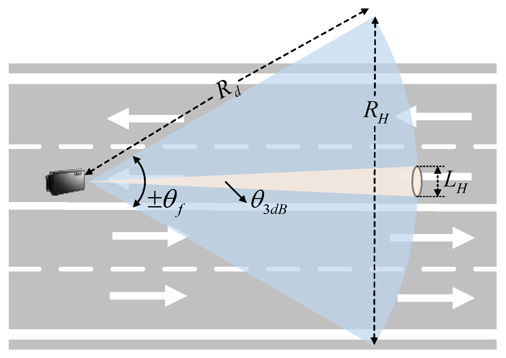
At detection range Rd, the required coverage in the cross-range defined as RH is determined by FOV, as illustrated in Figure 3. According to the geometric principle, we can determine that
R H = 2 R d s i n ( θ f ) .
We assume that the CARs are required to cover multiple lanes in both directions, which is defined as ±Dlane. Obviously, it can be expressed as
2 R d s i n θ f 2 D l a n e .
Thus, the first constraint of FOV can be defined as
g 1 ( d ) 0   g θ f , S j ( d ) + a r c s i n ( D l a n e / R d , S j ) 0 ,
2.
Actual aperture (DA);
Considering the far-field condition [27], the actual aperture is related to the detection range and signal wavelength, which can be defined as
2 D A 2 / λ R d .
The second constraint of the actual aperture can be expressed as
g 2 ( d ) 0     g D A , S j ( d ) λ R d , S j / 2 0 ,
3.
Virtual aperture (DV);
From Figure 3, the virtual aperture corresponds to the beam width, which represents the cross-range resolution LH
L H = 2 R d s i n ( θ 3 d B / 2 ) = 2 R d s i n ( k λ / 2 D V ) ,
where k denotes a constant factor.
To effectively distinguish the adjacent vehicles, the required cross-range resolution can be defined as Dvel, which denotes the width of vehicles. Therefore, the third constraint of the virtual aperture can be derived as
g 3 ( d ) 0   g D V , S j ( d ) + k λ 2 a r c s i n ( D v e l / 2 R d , S j ) 0.
4.
Physical limitations.
In practical applications, it is required that no overlap between antennas of the physical array is allowed, i.e., the fourth constraint for the MAM-MIMO sparse array can be expressed as
g 4 ( d ) 0     { i , j , g T x ( d ) + λ / 2 = | x i x j | + λ / 2 0 i , j , g R y ( d ) + λ / 2 = | y i y j | + λ / 2 0.
Herein, the high-dimensional optimization model for MAM-MIMO sparse array has been derived. Obviously, this model is a multi-objective optimization problem, which means it is difficult for the conventional methods to achieve the optimized solution simultaneously. Therefore, we purposefully propose a hierarchical genetic algorithm based on the multi-objective decomposition method, which is described in detail in the next subsection.

2.3. Optimization Algorithm

In recent years, the distribution equation of array antennas was proposed in [35], in which the optimal antenna positions can be directly calculated. Nevertheless, this method cannot take the minimum spacing constraint between adjacent antennas into consideration. Furthermore, a differential evolution algorithm was presented in [36]. This method can obtain the optimal antenna positions via coding and performing differential operations; however, it easily falls into a local optimum. Moreover, non-dominated sorting genetic algorithm Ⅲ (NSGA Ⅲ) has been presented to resolve the multi-objective optimization problem [37,38]. However, this algorithm cannot utilize the inherent connection between multiple objective functions. The solution obtained by this algorithm is usually a set of equilibrium solutions, which consist of multiple pareto optimal solutions.
To address the above issues, the genetic algorithm has been widely used in array position optimization due to its global search ability [39,40,41,42]. On this basis, we propose a hierarchical genetic algorithm based on the multi-objective decomposition method. Utilizing the hierarchical operation, the proposed algorithm is configured with different parameters for each population, thus increasing the population diversity to obtain the optimal solution favorably. Additionally, this algorithm can transform the multiple objective functions into a scalar problem by decomposition. The proposed algorithm is described as follows.

2.3.1. Processing Flow

In optimization processing, the objective functions matrix of Z individuals can be expressed as
F = [ f M , S 1 1 f M , S j + 1 1 f D , S 1 1 f D , S j + 1 1 f M , S 1 Z f M , S j + 1 Z f D , S 1 Z f D , S j + 1 Z ] .
To nondimensionalize the results of multiple objective functions, we first perform reverse normalization for this matrix, which is defined as
f ˜ M / D , S j z = m a x ( f M / D , S j 1 : Z ) f M / D , S j z m a x ( f M / D , S j 1 : Z ) m i n ( f M / D , S j 1 : Z ) .
Thereafter, the fitness of the zth individual can be defined as
f i t n e s s z = J = 1 j + 1 λ M , S J × f ˜ M , S J z + J = 1 j + 1 λ D , S J × f ˜ D , S J z ,
where λ M , S J and λ D , S J denote the weights for multiple objective functions. Their definitions can be calculated by criteria importance though the intercrieria correlation (CITIC) method [43,44]. The weights using the CITIC method are comprehensive measurements by considering the variability magnitude of each objective function and taking into account the correlation between multiple objective functions.
The variability magnitude of each objective function can be expressed as
V M / D , S J = z = 1 Z ( f ˜ M / D , S J z 1 Z z = 1 Z f ˜ M / D , S J z ) 2 Z 1 .
The correlation between multiple objective functions can be defined as
R M / D , S J = I = 1 j + 1 ( 1 r I J ) ,
where r I J represents the correlation coefficient and is expressed as
r I J = z = 1 Z ( f ˜ M / D , S I z 1 Z z = 1 Z f ˜ M / D , S I z ) ( f ˜ M / D , S J z 1 Z z = 1 Z f ˜ M / D , S J z ) z = 1 Z ( f ˜ M / D , S I z 1 Z z = 1 Z f ˜ M / D , S I z ) 2 z = 1 Z ( f ˜ M / D , S J z 1 Z z = 1 Z f ˜ M / D , S J z ) 2 .
Finally, referring to [43], the weights for multiple objective functions are constructed as
λ M / D , S J = ( V M / D , S J R M / D , S J ) / ( I = 1 j + 1 V M / D , S I R M / D , S I ) .
Utilizing the multi-objective decomposition method, the multiple objective functions can be jointly resolved with their inherent connections. The flowchart of the proposed algorithm is presented in Figure 4, and the processing steps are described as follows.
  • Initialization. Q subpopulations are generated as the upper genetic algorithm (GA) input, and each subpopulation with Z individuals is the lower GA input. Each individual consists of the array antenna spacing d, generated by binary coding rules.
  • Evaluation at upper GA. The fitness of all individuals is calculated according to Equation (26), thus obtaining the average of each subpopulation as the evaluation metric at the upper GA.
  • Selection, crossover, and mutation at upper GA. Multi-subpopulations are processed with selection, crossover, and mutation based on the evaluation metric calculated in step 2. Then the offspring subpopulations can be obtained.
  • Evaluation at lower GA. Similar to step 2, the fitness of all individuals in each subpopulation is calculated as the evaluation metric at lower GA.
  • Selection, crossover and mutation at lower GA. Similar to step 3, within the subpopulation, the operations of selection, crossover, and mutation are performed on the individuals.
  • Termination at lower GA. If the individual fitness is stable for multiple iterations at the lower GA, the current multi-subpopulation can be output; otherwise, skip to step 4.
  • Termination at upper GA. If the average fitness of the multi-subpopulation is stable for multiple iterations at the upper GA, the individual with the lowest fitness can be output as the optimized result; otherwise, output the multi-subpopulation and skip to step 3.
After several iterations with this processing, the optimal individual with the lowest fitness, i.e., the optimized MAM-MIMO sparse array design for CARs, can be achieved.

2.3.2. Computational Complexity Analysis

There are Q × Z individuals in the lower GA, and the complexity of their multi-objective functions are O ( j Q Z N u m ) , where j and Num represent the number of subarray types and beams pointing in the given FOV. Moreover, the complexity of the fitness evaluation, selection, crossover, and mutation at the lower GA can be expressed as O ( 2 ( j + 1 ) Q Z ) . Thus, the total computational complexity of the lower GA is O ( I 1 ( j N u m + 2 j + 2 ) Q Z ) with I1 being the total number of lower GA iterations. Similarly, the computational complexity of the upper GA is O ( I 2 ( j + 2 ) Q ) with I2 being the total number of upper GA iterations, in which the individual fitness has been calculated in the lower GA. Therefore, the total computational complexity of the proposed algorithm can be approximately expressed as
O ( I 1 j N u m Q Z + I 2 j Q ) .

2.4. Sparse Array Assessment

In order to evaluate the optimized MAM-MIMO sparse array, angular measurement accuracy is a crucial metric that represents the direction-of-arrival (DOA) estimation performance. The angular measurement accuracy can be predicted by the Cramer–Rao bound (CRB), thus avoiding spending extensive time on numerical simulations.
Referring to [45], the azimuth CRB of the sparse array with the Gaussian model can be expressed as (32). To simplify the analysis, herein we assume that there is only a signal source with an azimuth of θ.
CRB = 1 2 S N R 2 γ H Λ a ( θ ) γ a H ( θ ) R 1 a ( θ ) ,
where SNR is the signal-to-noise ratio, R represents the covariance matrix, Λa(θ) is the orthogonal projection matrix of the guidance vector, and γ denotes the differentiation of the guidance vector, respectively. These variables can be derived as
R = S N R a ( θ ) a H ( θ ) + I ,
Λ a ( θ ) = I a ( θ ) ( a H ( θ ) a ( θ ) ) 1 a H ( θ ) ,
γ = a ( θ ) / θ = j 2 π c o s θ d a ( θ ) .
According to the above definitions, we can further derive that
a H ( θ ) R 1 a ( θ ) = a H ( θ ) ( S N R a ( θ ) a H ( θ ) + I ) 1 a ( θ ) = i 2 N T N R 1 + i 2 N T N R S N R ,
γ H Λ a ( θ ) γ = 2 π 2 c o s 2 θ i 2 N T N R ( 2 i 2 N T N R l = 1 i 2 N T N R d l 2 ( l = 1 i 2 N T N R d l ) 2 ) .
Therefore, the subarray CRB, composed of i radars with i × NT transmitters and i × NR receivers, can be rewritten as
CRB = 1 + i 2 N T N R S N R 8 × S N R 2 × π 2 c o s 2 θ ( ( i 2 N T N R ) l = 1 i 2 N T N R d l 2 ( l = 1 i 2 N T N R d l ) 2 ) .
When i 2 N T N R 1 , Equation (37) can be simplified as
CRB i 2 N T N R 8 × S N R × π 2 c o s 2 θ ( ( i 2 N T N R ) l = 1 i 2 N T N R d l 2 ( l = 1 i 2 N T N R d l ) 2 ) .

3. Numerical Simulations

In this section, based on the scenario analysis of expressways or urban roads, a MAM-MIMO sparse array for CARs composed of three radars, each with two transmitters and six receivers, is optimized using the proposed method. With the optimized sparse array, the antenna pattern and sidelobe suppression performance of the multi subarray are demonstrated. Thereafter, the array design robustness on sidelobe suppression is verified by imperfection simulations. Additionally, we have compared the CRB of the sparse array with the uniform half-wavelength array. Finally, with the processing of multi-target echoes, the optimized sparse array is verified to have simultaneous detection capabilities for multiple types.
In CARs, the multiple subarrays consist of one of the radars for SRS, two adjacent radars for MRS, and three radars together for LRS. Herein, it is noted that the antenna spacing sets the integer multiple of 0.1λ, and the minimum antenna spacing is a half-wavelength for engineering practicality.
According to the detection demands of expressways or urban roads, the parameters for different subarrays are given in Table 2. In addition, Table 3 provides the operation parameters for the proposed genetic algorithm.

3.1. Optimized Sparse Array and Sidelobe Suppression

Utilizing the proposed method, the antenna positions within the optimized sparse array are illustrated in Figure 5 and Table 4. In the optimized MAM-MIMO sparse array, the three subarrays are composed of the first radar for SRS, the two radars on the left for MRS, and all the radars for LRS.
The antenna patterns of three subarrays are presented in Figure 6. For each subarray, its antenna patterns are simulated with three beams pointing, which can verify the stability of the optimized sparse array at different beams pointing directly. Moreover, the beam widths of the three subarrays are 5.38°, 1.46°, and 0.65°, showing that the FOVs of the three subarrays can satisfy the detection demands simultaneously.
Furthermore, the sidelobe suppression performance within the whole FOV is investigated in Figure 7. Furthermore, we compared this with a sparse array, which only employs the objective functions and constraints of LRS without considering SRS and MRS.
Herein, the PSLR for multiple subarrays with a 0.1° interval is simulated. Clearly, in the given FOV, the optimized sparse array has excellent sidelobe suppression performance without significant fluctuation. In particular, the optimized sparse array can suppress the sidelobe with −10.16 dB for SRS, −12.09 dB for MRS, and −11.89 dB for LRS.
Compared with the sparse array considering only the LRS type, since the proposed method takes into account multiple types, there is a slight loss of approximately 1.4 dB. Nevertheless, the proposed sparse array can obtain significant improvement for the other two types. Consequently, utilizing the proposed method, the MAM-MIMO sparse array for CARs can satisfy the different detection demands simultaneously and suppress the antenna pattern sidelobe effectively.

3.2. Imperfect Factors Adaptation Analysis

In practical applications, imperfect factors, such as amplitude-phase errors and manufacturing errors, have an impact on sidelobe suppression. Therefore, these factors are required to be analyzed to ensure the robustness of the optimal sparse array. First, the evolution of the sidelobe with amplitude-phase errors is simulated. Herein, the amplitude-phase errors of different antennas are assumed to be uniformly distributed within 3 dB and 30°, which can be achieved by antenna calibration. In addition, the errors for each antenna are assumed to be independent.
One thousand Monte Carlo simulations are performed for each combination of amplitude-phase errors, where the beam pointing of all subarrays is set at 5°. The simulation results are demonstrated in Figure 8. With the increase in amplitude-phase errors, the sidelobe suppression performance declines gradually. Due to the small number of antennas, the sidelobe suppression in the SRS type decreases significantly, approximately 1.3 dB, and the declines for the other two types are 0.7 dB and 0.5 dB, respectively. Moreover, compared to the amplitude error, it is noted that the phase error has a worse effect on sidelobe suppression.
Thereafter, the evolution of the sidelobe with manufacturing errors is also simulated and presented in Figure 9. In CARs, the manufacturing errors include the adjacent antenna fabrication error within the unit radar and the assembly error between adjacent radars. Referring to the existing manufacturing process, we consider the fabrication error to be within 0.2 mm, and the assembly error is within 2 mm. Similarly, the manufacturing errors also obey a uniform distribution.
The sidelobe suppression performance also decreases with the manufacturing errors. Compared to the fabrication error, the assembly error can cause significant deterioration of the sidelobe suppression. It should be noted that the trend in Figure 9a is distinct from the others, due to the absence of an assembly error in the SRS type. Specifically, the sidelobe of these three types increased by 0.1 dB, 0.6 dB, and 1.0 dB, respectively.
In summary, due to the imperfection factors, the sidelobe suppression performance will decline slightly without significant distortion. Therefore, the optimized MAM-MIMO sparse array is robust regarding sidelobe suppression, which ensures engineering practicality.

3.3. Angular Measurement Accuracy

In this subsection, we utilize the CRB and digital beamforming (DBF) methods to evaluate the sparse array and compare them with the uniform half-wavelength array.
Referring to [45], the CRB of the uniform half-wavelength array can be calculated as
CRB U n i = 6 λ 2 ( 2 π ) 2 N 3 d 2 c o s 2 ( θ ) S N R ,
where N is the number of array antennas and d = λ/2.
Based on Equations (39) and (40), the CRB of the multi-subarray within the optimized sparse array and the uniform array can be calculated, as shown in Figure 10. The SNR of the single source is selected to be 5 dB to 20 dB, and its azimuth is set at 5°. Moreover, 1000 Monte Carlo simulations with the DBF method are performed to calculate the root mean square error (RMSE) of the azimuth estimation, which is denoted as
RMSE = 1 K t = 1 K ( θ ^ t θ 0 ) 2 .
The angular measurement accuracy of these subarrays is essentially equivalent to the uniform half-wavelength array. However, compared to the uniform array, the number of antennas utilized in these subarrays is only 66.7%, 62.3%, and 62.1% that of the uniform array. In particular, the estimation results can achieve accuracy superior to 0.1° in MRS and LRS types with the minimum detectable SNR (approximately 13 dB).

3.4. Detection Performance

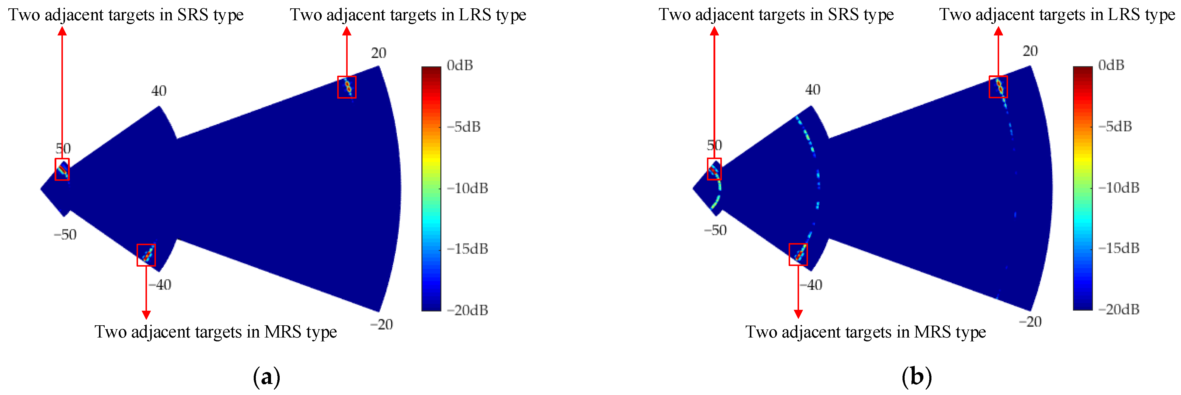
In this scenario, we construct the multi-target echoes and implemented azimuth estimation by DBF to demonstrate the optimized sparse array detection performance. The scenario consists of six targets, and their parameters are given in Table 5. The estimation results of the range–azimuth spectrum using the optimized sparse array are shown in Figure 11a. It is apparent that these targets can be focused, distinctly separated, and positioned exactly.
However, compared with the uniform array, as illustrated in Figure 11b, there is a sidelobe remaining at several angles. The remaining sidelobe is consistent with the simulations in Section 3.1, approximately −10 dB. In this regard, other estimation methods for the sparse array, such as CS and MC [46,47,48], can be employed to further suppress the sidelobe in the future.

4. Real-Data Results

To verify the feasibility of the proposed method, the real-data experiments utilizing the AWR1243P cascade radar are presented in this section. This cascade radar consists of four chips with twelve transmitters and sixteen receivers, as shown in Figure 12.

4.1. Simplified Optimized Sparse Array and Sidelobe Suppression

The AWR1243P cascade radar can form a uniform half-wavelength array with a virtual aperture of 42.5λ. Due to the limitation of the aperture, we simplify the optimization model, which is composed of SRS and MRS detection types. Herein, the antenna spacing is an integer multiple of the half-wavelength. In addition, these two subarrays are optimized with two radars for CARs, and each radar consists of three transmitters and four receivers. The simplified optimized sparse array is depicted in Figure 13 and Table 6. The SRS covering a FOV of ±45° is composed of three transmitters and four receivers on the left side, and the MRS covering a FOV of ±30° utilizes all antennas.
In terms of array sparsity, compared to the uniform half-wavelength array, the number of virtual antennas in the SRS type is 60.0%, while it is 57.8% in the MRS type. Before the experiments, we carried out the antenna calibration, which is performed by placing a corner reflector with a radar cross-section (RCS) of 5 dBsm at 10 m.
After antenna calibration, the corner reflector position is offset by 2 m in cross-range, i.e., its azimuth is approximately −11°. By collecting and processing the echoes, the antenna pattern of these two subarray types can be measured. Figure 14 presents the experimental results on sidelobe suppression.
Since the system errors cannot be fully calibrated, the measured sidelobe is slightly higher than the simulated results by approximately 2 dB, which is consistent with the imperfect factors adaptation analysis. Overall, these two subarrays utilizing real data can achieve 6.8 dB and 8.6 dB on the sidelobe suppression, while the simulated sidelobes are −9.7 dB and −10.5 dB.
In particular, the simulated sidelobe deviations between the sparse and uniform array is 3.5 dB in SRS type, while the measured deviations are less than 0.3 dB. Moreover, the simulated and measured sidelobes in the MRS type are both increased by approximately 2.6 dB, compared with the uniform array. Therefore, the optimized MAM-MIMO sparse array can achieve excellent sidelobe suppression with strong robustness.

4.2. Detection Performance

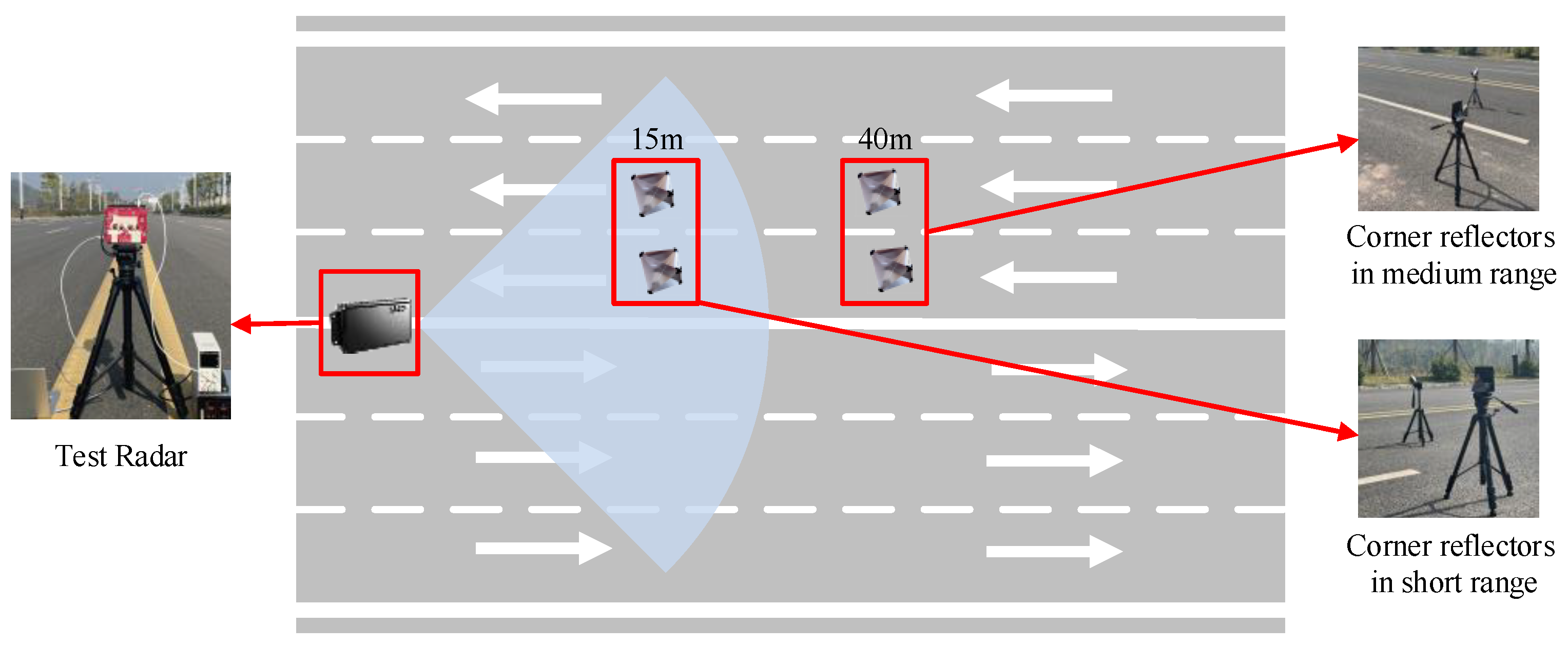
The scenario composed of four targets (corner reflectors) with ( r x 1 , r y 1 ) = ( 15   m , 3   m ) , ( r x 2 , r y 2 ) = ( 14.5   m ,   m ) , ( r x 3 , r y 3 ) = ( 40   m , 3   m ) , and ( r x 4 , r y 4 ) = ( 40   m , 5   m ) is set up to verify the detection performance of the simplified optimized sparse array, as shown in Figure 15.
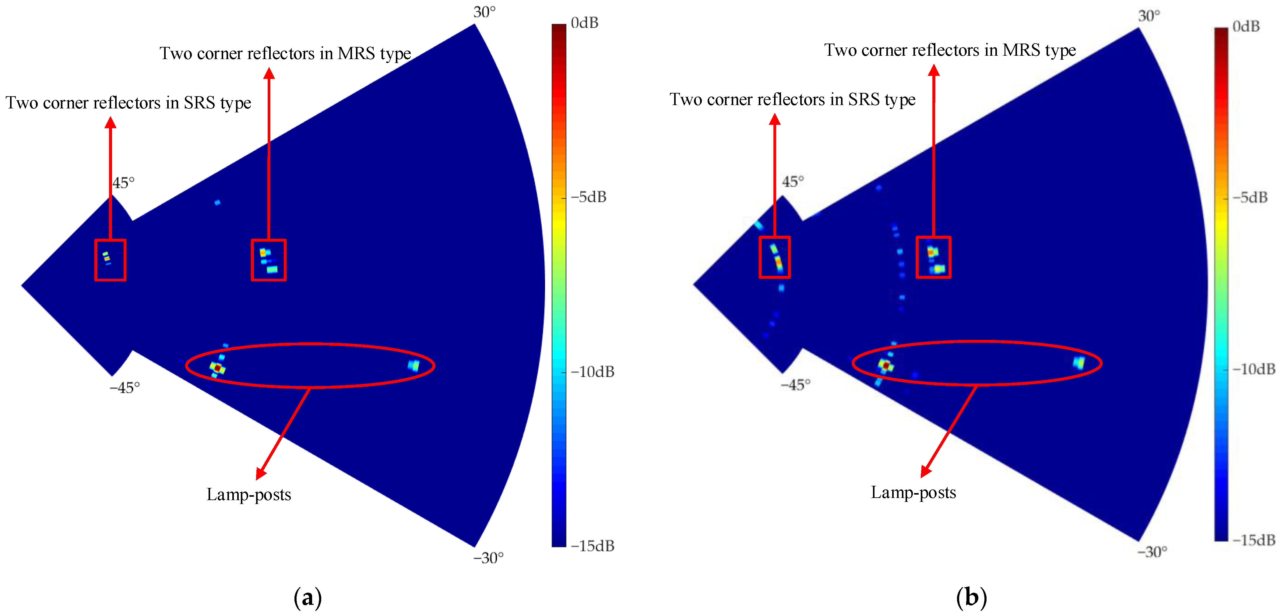
Using the AWR1243P cascade radar, the multi-target range–azimuth spectrum of the sparse and uniform array is depicted in Figure 16. Clearly, these targets in adjacent lanes can be effectively separated into SRS and MRS types. Moreover, the lamp posts at the edge of the FOV are effectively detected, which verifies the effectiveness of sidelobe suppression in the given FOV.
In summary, the proposed MAM-MIMO sparse array for CARs can effectively reduce the array antennas and the hardware complexity, while satisfying the multi-type detection demands simultaneously.

5. Conclusions

In this paper, a novel method for the MAM-MIMO sparse array design in automotive radar applications is proposed and described in detail. In order to satisfy the detection demands including the wide FOV, long range, and high resolution, the multi-subarray within the sparse array is designed by multi-aperture multiplexing.
The antenna positions in the MAM-MIMO sparse array are optimized to suppress the sidelobe for the multi-subarray simultaneously. The optimization model has been derived, in which the objective functions are found by employing the PSLR at all beams pointing. Furthermore, we have presented an improved genetic algorithm to obtain the optimal array configuration. Additionally, we also derive the Cramer–Rao bound of azimuth accuracy to evaluate the sparse array detection performance and compare it with the uniform half-wavelength array.
Utilizing the proposed method, the MAM-MIMO sparse array for CARs can achieve over 10 dB for multi-subarray sidelobe suppression, yet with reasonably high azimuth resolutions and large FOVs. Moreover, the optimized MAM-MIMO sparse array is validated to have strong robustness to antenna amplitude-phase errors and manufacturing errors. Finally, the real-data results verify the feasibility of the proposed method.

Author Contributions

Conceptualization, C.L. and Y.W.; methodology, C.L. and W.G.; software, W.G.; validation, C.L., Z.Y., and Q.P.; formal analysis, X.H. and L.Z.; writing—original draft preparation, C.L. and L.Z.; writing—review and editing, X.H. and W.G.; supervision, L.Z. and W.G. All authors have read and agreed to the published version of the manuscript.

Funding

This research was funded by the National Key R&D Program of China (Grant No. 2018YFE0202101, 2018YFE0202103), the China Postdoctoral Science Foundation (Grant No. 2021M690412), the Natural Science Foundation of Chongqing, China (Grant No. cstc2020jcyj-msxmX0812), and project ZR2021MF134 supported by the Shandong Provincial Natural Science Foundation.

Data Availability Statement

Data available on request.

Conflicts of Interest

The authors declare no conflict of interest.

References

  1. Fleming, B. Recent Advancement in Automotive Radar Systems [Automotive Electronics]. IEEE Veh. Technol. Mag. 2012, 7, 4–9. [Google Scholar] [CrossRef]
  2. Harter, M.; Hildebrandt, J.; Ziroff, A.; Zwick, T. Self-Calibration of a 3-D-Digital Beamforming Radar System for Automotive Applications with Installation Behind Automotive Covers. IEEE Trans. Microw. Theory Tech. 2016, 64, 2994–3000. [Google Scholar] [CrossRef]
  3. Patole, S.M.; Torlak, M.; Wang, D.; Ali, M. Automotive radars: A review of signal processing techniques. IEEE Signal Process. Mag. 2017, 34, 22–35. [Google Scholar] [CrossRef]
  4. Engels, F.; Heidenreich, P.; Zoubir, A.M.; Jondral, F.K.; Wintermantel, M. Advances in Automotive Radar: A framework on computationally efficient high-resolution frequency estimation. IEEE Signal Process. Mag. 2017, 34, 36–46. [Google Scholar] [CrossRef]
  5. Hu, X.; Lu, M.; Li, Y.; Wang, Y. Motion Compensation for TDM MIMO Radar by Sparse Reconstruction. Electron. Lett. 2017, 53, 1604–1606. [Google Scholar] [CrossRef]
  6. Kim, G.; Mun, J.; Lee, J. A Peer-to-Peer Interference Analysis for Automotive Chirp Sequence Radars. IEEE Trans. Veh. Technol. 2018, 67, 8110–8117. [Google Scholar] [CrossRef]
  7. Roos, F.; Bechter, J.; Knill, C.; Schweizer, B.; Waldschmidt, C. Radar Sensors for Autonomous Driving: Modulation Schemes and Interference Mitigation. IEEE Microw. Mag. 2019, 20, 58–72. [Google Scholar] [CrossRef] [Green Version]
  8. Hu, X.; Li, Y.; Lu, M.; Wang, Y.; Yang, X. A Multi-Carrier-Frequency Random-Transmission Chirp Sequence for TDM MIMO Automotive Radar. IEEE Trans. Veh. Technol. 2019, 68, 3672–3685. [Google Scholar] [CrossRef]
  9. Uysal, F. Phase-Coded FMCW Automotive Radar: System Design and Interference Mitigation. IEEE Trans. Veh. Technol. 2020, 69, 270–281. [Google Scholar] [CrossRef] [Green Version]
  10. Zhang, X.; Jiang, W.; Huo, K.; Liu, Y.; Li, X. Robust Adaptive Beamforming Based on Linearly Modified Atomic-Norm Minimization with Target Contaminated Data. IEEE Trans. Signal Process. 2020, 68, 5138–5151. [Google Scholar] [CrossRef]
  11. Wang, J. CFAR-Based Interference Mitigation for FMCW Automotive Radar Systems. IEEE Trans. Intell. Transp. Syst. 2021. [Google Scholar] [CrossRef]
  12. Ciattaglia, G.; Santis, A.D.; Disha, D.; Spinsante, S.; Castellini, P.; Gambi, E. Performance Evaluation of Vibrational Measurements through mmWave Automotive Radars. Remote Sens. 2021, 13, 98. [Google Scholar] [CrossRef]
  13. Hasch, J.; Topak, E.; Schnabel, R.; Zwick, T.; Weigel, R.; Waldschmidt, C. Millimeter-Wave Technology for Automotive Radar Sensors in the 77 GHz Frequency Band. IEEE Trans. Microw. Theory Tech. 2012, 60, 845–860. [Google Scholar] [CrossRef]
  14. Schneider, M. Automotive Radar—Status and Trends. In Proceeding of the 2005 German Microwave Conference (GeMiC 2005), Ulm, Germany, 5–7 April 2005. [Google Scholar]
  15. Xu, J.; Hong, W.; Zhang, H.; Wang, G.; Yu, Y.; Jiang, Z.H. An Array Antenna for Both Long- and Medium-Range 77 GHz Automotive Radar Applications. IEEE Trans. Antennas Propag. 2017, 65, 7207–7216. [Google Scholar] [CrossRef]
  16. Yu, Y.; Hong, W.; Zhang, H.; Xu, J.; Jiang, Z.H. Optimization and Implementation of SIW Slot Array for Both Medium- and Long-Range 77 GHz Automotive Radar Application. IEEE Trans. Antennas Propag. 2018, 66, 3769–3774. [Google Scholar] [CrossRef]
  17. Guo, Z.J.; Hao, Z.C. A Compact Wideband Millimeter-Wave Substrate-Integrated Double-Line Slot Array Antenna. IEEE Trans. Antennas Propag. 2020, 69, 882–891. [Google Scholar] [CrossRef]
  18. Design Guide: TIDEP-01012 Imaging Radar Using Cascaded Mmwave Sensor Reference Design. Available online: https://www.ti.com/lit/ug/tiduen5a/tiduen5a.pdf (accessed on 16 April 2020).
  19. Abdullah, H.; Mabrouk, M.; Kabeel, A.E.; Hussein, A. High-Resolution and Large-Detection-Range Virtual Antenna Array for Automotive Radar Applications. Sensors 2021, 21, 1702. [Google Scholar] [CrossRef]
  20. Lee, S.; Kim, S.C. Logarithmic-Domain Array Interpolation for Improved Direction of Arrival Estimation in Automotive Radars. Sensors 2019, 19, 2410. [Google Scholar] [CrossRef] [Green Version]
  21. Yoo, S.; Milyakh, Y.; Kim, H.; Hong, C.; Choo, H. Patch Array Antenna Using a Dual Coupled Feeding Structure for 79 GHz Automotive Radar Applications. IEEE Antennas Wirel. Propag. Lett. 2020, 19, 676–679. [Google Scholar] [CrossRef]
  22. Sun, S.; Petropulu, A.P.; Poor, H.V. MIMO Radar for Advanced Driver-Assistance Systems and Autonomous Driving: Advantages and Challenges. IEEE Signal Process. Mag. 2020, 37, 98–117. [Google Scholar] [CrossRef]
  23. Sun, S.; Zhang, Y.D. 4D Automotive Radar Sensing for Autonomous Vehicles: A Sparsity-Oriented Approach. IEEE J. Sel. Top. Signal Process. 2021, 15, 879–891. [Google Scholar] [CrossRef]
  24. Yang, X.; Li, Y.; Liu, F.; Lan, T.; Long, T.; Sarkar, T.K. Antenna Position Optimization Method Based on Adaptive Genetic Algorithm with Self-Supervised Differential Operator for Distributed Coherent Aperture Radar. IET Radar Sonar Nav. 2021, 15, 677–685. [Google Scholar] [CrossRef]
  25. Dong, J.; Li, Q.; Guo, W. A Combinatorial Method for Antenna Array Design in Minimum Redundancy MIMO Radars. IEEE Antennas Wireless Propag. Lett. 2009, 8, 1150–1153. [Google Scholar] [CrossRef]
  26. Lange, O.; Yang, B. Antenna Geometry Optimization for 2D Direction-of-Arrival Estimation for Radar Imaging. In Proceedings of the International ITG Workshop on Smart Antennas, Aachen, Germany, 24–25 February 2011. [Google Scholar]
  27. Tan, K.; Wu, S.; Wang, Y.; Ye, S.; Chen, J.; Liu, X.; Fang, G.; Yan, S. On Sparse MIMO Planar Array Topology Optimization for UWB Near-Field High-Resolution Imaging. IEEE Trans. Antennas Propag. 2017, 65, 989–994. [Google Scholar] [CrossRef]
  28. Ma, Y.; Miao, C.; Zhao, Y.; Wu, W. An MIMO Radar System Based on the Sparse-Array and Its Frequency Migration Calibration Method. Sensors 2019, 19, 3580. [Google Scholar] [CrossRef] [PubMed] [Green Version]
  29. Wang, J.; Aubry, P.; Yarovoy, A. 3-D Short-Range Imaging with Irregular MIMO Arrays Using NUFFT-Based Range Migration Algorithm. IEEE Trans. Geosci. Remote Sens. 2020, 58, 4730–4742. [Google Scholar] [CrossRef]
  30. Serio, A.D.; Hügler, P.; Roos, F.; Waldschmidt, C. 2-D MIMO Radar: A Method for Array Performance Assessment and Design of a Planar Antenna Array. IEEE Trans. Antennas Propag. 2020, 68, 4604–4616. [Google Scholar] [CrossRef]
  31. Bialer, O.; Jonas, A.; Tirer, T. Super Resolution Wide Aperture Automotive Radar. IEEE Sens. J. 2021, 21, 17846–17858. [Google Scholar] [CrossRef]
  32. Feger, R.; Pfeffer, C.; Scheiblhofer, W.; Schmid, C.M.; Lang, M.J.; Stelzer, A. A 77-GHz Cooperative Radar System Based on Multi-Channel FMCW Stations for Local Positioning Applications. IEEE Trans. Microw. Theory Tech. 2013, 61, 676–684. [Google Scholar] [CrossRef]
  33. Frischen, A.; Hasch, J.; Waldschmidt, C. A Cooperative MIMO Radar Network Using Highly Integrated FMCW Radar Sensors. IEEE Trans. Microw. Theory Tech. 2017, 65, 1355–1366. [Google Scholar] [CrossRef]
  34. Edstaller, S.; Mueller, D. A Cooperative Radar System with Active Reference Target Synchronization for Kinematic Target Analysis. IEEE Trans. Microw. Theory Tech. 2021, 69, 4118–4131. [Google Scholar] [CrossRef]
  35. Zhang, Y.; Bao, Z. Study of Optimum Thinning Arrays by Nonuniform Spacings. Electron. J. 1989, 17, 81–87. [Google Scholar]
  36. Kurup, D.G.; Himdi, M.; Rydberg, A. Synthesis of uniform amplitude unequally spaced antenna arrays using the differential evolution algorithm. IEEE Trans. Antennas Propag. 2003, 51, 2210–2217. [Google Scholar] [CrossRef]
  37. Deb, K.; Jain, H. An Evolutionary Many-Objective Optimization Algorithm Using Reference-Point-Based Nondominated Sorting Approach, Part I: Solving Problems with Box Constraints. IEEE Trans. Evol. Comput. 2014, 18, 577–601. [Google Scholar] [CrossRef]
  38. Jain, H.; Deb, K. An Evolutionary Many-Objective Optimization Algorithm Using Reference-Point Based Nondominated Sorting Approach, Part II: Handling Constraints and Extending to an Adaptive Approach. IEEE Trans. Evol. Comput. 2014, 18, 602–622. [Google Scholar] [CrossRef]
  39. Bray, M.G.; Werner, D.H.; Boeringer, D.W.; Machuga, D.W. Optimization of thinned aperiodic linear phased arrays using genetic algorithms to reduce grating lobes during scanning. IEEE Trans. Antennas Propag. 2002, 50, 1732–1742. [Google Scholar] [CrossRef]
  40. Chen, K.; Yun, X.; He, Z.; Han, C. Synthesis of Sparse Planar Arrays Using Modified Real Genetic Algorithm. IEEE Trans. Antennas Propag. 2007, 55, 1067–1073. [Google Scholar] [CrossRef]
  41. Cen, L.; Yu, Z.L.; Ser, W.; Cen, W. Linear Aperiodic Array Synthesis Using an Improved Genetic Algorithm. IEEE Trans. Antennas Propag. 2012, 60, 895–902. [Google Scholar] [CrossRef]
  42. Cheng, Y.F.; Shao, W.; Zhang, S.J.; Li, Y.P. An Improved Multi-Objective Genetic Algorithm for Large Planar Array Thinning. IEEE Trans. Magn. 2016, 52, 511–523. [Google Scholar] [CrossRef]
  43. Lin, Z.; Wen, F.; Wang, H.; Lin, G.; Mo, T.; Ye, X. CRITIC-Based Node Importance Evaluation in Skeleton-Network Reconfiguration of Power Grids. IEEE Trans. Circuits-II 2018, 65, 206–210. [Google Scholar] [CrossRef]
  44. Yu, S.; Liu, H.; Bai, L.; Han, F. Study on the Suitability of Passive Energy in Public Institutions in China. Energies 2019, 12, 2446. [Google Scholar] [CrossRef] [Green Version]
  45. Stoica, P.; Nehorai, A. Performance Study of Conditional and Unconditional Direction-of-Arrival Estimation. IEEE Trans. Acoust. Speech Signal Process. 1990, 38, 1783–1795. [Google Scholar] [CrossRef]
  46. Hu, X.; Tong, N.; Wang, J.; Ding, S.; Zhao, X. Matrix Completion-Based MIMO Radar Imaging with Sparse Planar Array. Signal Process. 2017, 131, 49–57. [Google Scholar] [CrossRef]
  47. Hu, X.; Zhang, L.; Long, J.; Liang, C.; Liu, J.; Wang, Y. High-Resolution Velocity-Azimuth Joint Estimation for Random-Time-Division-Multiplexing Multiple-Input-Multiple-Output Automotive Radar Using Matrix Completion. IET Radar Sonar Nav. 2021, 15, 1281–1296. [Google Scholar] [CrossRef]
  48. Lee, S.; Jung, Y.; Lee, M.; Lee, W. Compressive Sensing-Based SAR Image Reconstruction from Sparse Radar Sensor Data Acquisition in Automotive FMCW Radar System. Sensors 2021, 21, 7283. [Google Scholar] [CrossRef] [PubMed]
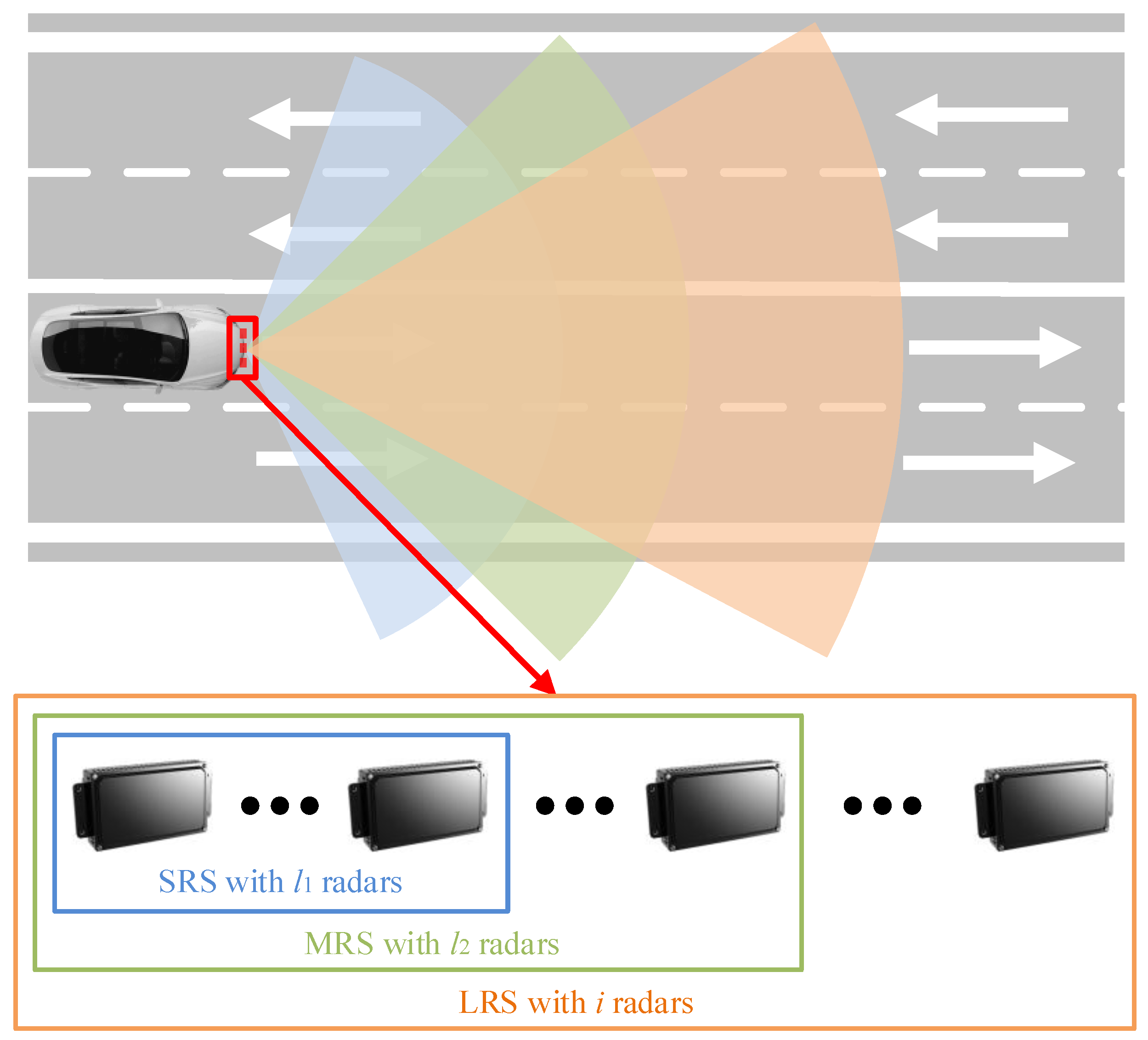
Figure 1. The cooperative automotive radars with multiple heterogeneous radars.
Electronics 11 01198 g001
Figure 2. Symbolic representation in one of the subarrays.
Electronics 11 01198 g002
Figure 3. The schematic for automotive radar sensing.
Electronics 11 01198 g003
Figure 4. The flowchart of the improved genetic algorithm.
Electronics 11 01198 g004
Figure 5. The optimized MAM-MIMO sparse array for CARs.
Electronics 11 01198 g005
Figure 6. The optimal MAM-MIMO sparse array antenna patterns at different beams pointing: (a) SRS detection type; (b) MRS detection type; (c) LRS detection type.
Electronics 11 01198 g006
Figure 7. The PSLR of the optimal MAM-MIMO sparse array and only LRS method in the given FOV: (a) SRS detection type; (b) MRS detection type; (c) LRS detection type.
Electronics 11 01198 g007
Figure 8. The sidelobe suppression performance with amplitude-phase errors: (a) SRS detection type; (b) MRS detection type; (c) LRS detection type.
Electronics 11 01198 g008
Figure 9. The sidelobe suppression performance with manufacturing errors: (a) SRS detection type; (b) MRS detection type; (c) LRS detection type.
Electronics 11 01198 g009
Figure 10. The comparison results of angular measurement accuracy for multi-subarray: (a) SRS detection type; (b) MRS detection type; (c) LRS detection type.
Electronics 11 01198 g010
Figure 11. The estimation results of the range–azimuth spectrum: (a) The MAM-MIMO sparse array for CARs; (b) the uniform half-wavelength array.
Electronics 11 01198 g011
Figure 12. The AWR1243P four-chip cascade radar.
Electronics 11 01198 g012
Figure 13. The simplified optimized MAM-MIMO sparse array for CARs.
Electronics 11 01198 g013
Figure 14. The sidelobe suppression performance of the optimized array compared with the uniform half-wavelength array: (a) SRS detection type; (b) MRS detection type.
Electronics 11 01198 g014
Figure 15. Photograph of radar deployment and test scene.
Electronics 11 01198 g015
Figure 16. The measured range–azimuth spectrum estimation results with real data: (a) The MAM-MIMO sparse array for CARs; (b) the uniform half-wavelength array.
Electronics 11 01198 g016
Table 1. Automotive radar classifications with their classical system parameters.
TypeLRRMRRSRR
Detection range10–200 m1–100 m0.2–30 m
Azimuth beam width1.5°
Field-of-view±15°±30°±60°
Table 2. The technical parameters for multi-subarray in reference to [10,15].
TypeLRSMRSSRS
DemandsDetection range0.2–20 m20–80 m80–200 m
Cross-range coverage±15 m (8 lanes)
Cross-range resolution2 m
ConstraintsBeam width≤7°≤1.5°≤0.8°
Field-of-viewsuperior to ±45°superior to ±30°superior to ±15°
Actual Aperture≤7λ≤30λ≤60λ
Virtual Aperture≥8λ≥40λ≥80λ
Table 3. The operation parameters used in proposed genetic algorithm.
Subpopulation123456Upper
individual number5050505050506
crossover probability0.70.70.60.60.50.50.5
mutation probability0.050.010.050.010.050.010.02
crossover points number1122333
mutation points number1313132
Table 4. Transmitter and receiver positions within the optimized MAM-MIMO sparse array.
xT,I and yR,I in λ
xT,10yR,10.6yR,713.4yR,1338.6
xT,24.8yR,21.2yR,814.4yR,1439.6
xT,312.4yR,32.4yR,915.4yR,1540.3
xT,419.7yR,43.0yR,1016.6yR,1641.3
xT,537.9yR,53.6yR,1117.8yR,1742.3
xT,643.7yR,64.2yR,1218.8yR,1843.2
Table 5. Multi-target parameters setting.
TargetRangeAzimuthVelocity
116 m45°0 m/s
216 m39°0 m/s
370 m−33°5 m/s
470 m−31.5°5 m/s
5180 m18°−10 m/s
6180 m18.8°−10 m/s
Table 6. Transmitter and receiver positions of the example for experiments.
xT,I and yR,I in λ
xT,14.5xT,416.5yR,10yR,516.5
xT,26.0xT,518.5yR,23.0yR,619.5
xT,37.0xT,620.0yR,35.0yR,722.5
yR,47.0yR,825.5
Publisher’s Note: MDPI stays neutral with regard to jurisdictional claims in published maps and institutional affiliations.