Article

Enhanced Control of Three-Phase Grid-Connected Renewables with Fault Ride-Through Capability under Voltage Sags

by
Alexis B. Rey-Boué
1,*,
N. F. Guerrero-Rodríguez
2,
Johannes Stöckl
3 and
Thomas I. Strasser
3
1
Department of Electronics, Computers Technology and Projects, Universidad Politécnica de Cartagena, c/Dr. Fleming, s/n, 30202 Cartagena, Spain
2
Engineering Sciences, Pontificia Universidad Católica Madre y Maestra PUCMM, Av. Abraham Lincoln Esq. Romulo Betancourt, Santo Domingo 2748, Dominican Republic
3
AIT Austrian Institute of Technology, Center for Energy-Electric Energy Systems, Giefinggasse 2, 1210 Vienna, Austria
*
Author to whom correspondence should be addressed.
Electronics 2022, 11(9), 1404; https://doi.org/10.3390/electronics11091404
Submission received: 15 March 2022 / Revised: 21 April 2022 / Accepted: 22 April 2022 / Published: 27 April 2022
(This article belongs to the Section Power Electronics)

Abstract

:
The uninterruptible operation of grid-connected renewables under the occurrence of grid voltage sags is addressed in this work. This is achieved due to the incorporation of an enhanced control algorithm of a renewable source. The low-voltage ride-through algorithm was developed in accordance to the voltage profile introduced by IEC 61400-21 regarding grid voltage sags. To guarantee continuous operation of the renewable agent during voltage sags, not only instantaneous reactive power but also instantaneous active power under moderate voltage sags was injected to the utility grid fulfilling grid code requirements. A dual second-order generalized integrator frequency-locked loop synchronization algorithm was used to estimate the system’s frequency, together with the positive and the negative sequences of the three-phase utility grid voltages when unbalanced sags occurred. The current control was made in a stationary reference frame by using proportional-resonant regulators, and a DC voltage source was used to emulate the primary energy from any type of renewable system. The validation of the proposed control algorithm was conducted for a three-phase grid-connected renewable system with an apparent power of 500 kVA. The results from several experimental tests demonstrated the proper behavior of the enhanced algorithm.

1. Introduction

During the last decade, an increased penetration of renewables in power grids has been reported in the literature [1,2] stating that the stability of electric power systems could be compromised. This fact has encouraged countries with high penetration levels of renewables to become aware of the necessity of energy standards focused to regulate the operation of grid-connected renewable power generators [3,4,5,6]. Among them, low-voltage ride-through (LVRT) capability has been established for the exerted control of distributed generators (DG), avoiding the disconnection of inverter-based distributed energy resources (DER), such as photovoltaic (PV) inverters or wind generators from the mains during voltage sags.
Due to the importance of the LVRT capability for renewables, it is commonly added to the control subsystems of DGs. Several works regarding this topic can be found in the literature [7,8,9,10,11]. To comply with electrical regulations—along with the tasks that must be performed by LVRT—it is important to compute the positive- and negative-sequence component (PS and NS) values of the three-phase voltages and currents of the mains to deliver instantaneous reactive power (Q), which improves the voltage profile when voltage sags occur. This is also necessary to limit the amplitude of the currents through the three-phase voltage source inverter (VSI), preventing its disconnection from the grid due to overcurrent triggering.
A predictive control scheme able to generate a signal fault reference for the LVRT capability of a two-stage PV grid-connected inverter was presented in [12]. In this work, a battery buffer was used in the DC stage that was able to absorb or inject power to compensate for the changes in the DC link voltage from its nominal value during voltage sags. The results demonstrated that, using the proposed LVRT capability scheme, the DC link voltage variations were reduced when compared to other LVRT schemes. The maximum instantaneous active power (P) was injected to the mains in normal operating conditions, whereas some Q was injected when voltage sags occurred, fulfilling grid code requirements [12]. Since an energy storage device was used, an increased price was expected, which is a drawback for large-scale PV systems, usually limiting this strategy to small PV generators.
Wind turbines that use doubly fed induction generators (DFIGs) are susceptible to faults in the power grid, but grid codes also require that they stay connected when voltage sags occur. Therefore, LVRT capability needs to be added to the control subsystems of such generators. In [13], a control regulator based on neuro fuzzy logic parallel resonance and a fault current limitation were presented to enhance the LVRT ancillary algorithm of DFIG wind farm systems. A better behavior of this scheme was observed compared to similar ones because of its capability to adapt to changes in the system dynamics. However, experiments were not conducted to validate the proposed LVRT strategy in a real scenario. An improvement of the LVRT algorithm for the DFIG wind turbines in a grid fault condition was achieved in [14] with a modified control scheme for the rotor-side converter (RSC). A comparative study was carried out with other schemes by using a simulation model of a 1.5 MW DFIG wind turbine. The achievements demonstrated that the proposed design, which generated valid rotor voltage references, met the LVRT requirements of the DFIG. However, in the study no experimental tests were performed under real conditions.
A LVRT strategy for modular multilevel converter (MMC) PV grid-connected systems using model predictive control (MPC) was discussed in [15]. This approach was tested under asymmetric conditions using real-time simulations. By the implementation of the LVRT strategy, the NS value of the AC currents were cancelled, the peaks of the three-phase currents were limited, and a power balance of the AC and DC sides was reached to normalize the DC-side voltage. The results showed that a good performance of the LVRT strategy was attained, but a complex and sophisticated control strategy is necessary to be developed and implemented in a real grid-connected inverter system.
To develop an LVRT scheme, it is mandatory that the synchronization algorithms are able to compute not only the utility grid phase or frequency during the occurrence of voltage sags, but also the PS and the NS values of the three-phase grid voltages. An inaccurate phase angle or frequency detection leads to poor LVRT performance of grid-connected inverters. Hence, a reliable synchronization algorithm must be used to guarantee robust current control in the control subsystems of the inverters. For example, the synchronization method described in [16] in a synchronous reference frame (SRF) (dq axes) only computed the phase angle and the PS value of the grid voltages, whereas the decoupled double SRF phase-locked loop (PLL) [17] in two SRFs could be implemented to compute the phase angle, together with the PS and the NS values during the occurrence of unbalanced (asymmetrical) voltage sags.
On the other hand, two enhanced synchronization algorithms that are also able to estimate the utility grid frequency, the PS, and the NS values of grid voltages during voltage sags with higher dynamics can be implemented on αβ axes (which is also called a stationary reference frame). These are the dual second-order generalized integrator frequency-locked loop (DSOGI-FLL) [18] and the multiple second-order generalized integrator frequency-locked loop (MSOGI-FLL) [19]. The latter is also capable of separating the harmonics components of the mains from its fundamental nominal frequency (ω0), but a high computational burden is needed. Eventually, a stiff grid (Z → 0) is considered in this paper, and the effect of the harmonics can be neglected. Hence, the DSOGI-FLL synchronization algorithm, which is easier to implement, is used.
The main goal of the present work is to present the design and implementation of a strategy to control a three-phase grid-connected renewable energy system when voltage sags occur in the mains. It is characterized to attain the correct control of P and Q by applying an enhanced LVRT in the control of the grid-connected VSI. Control of the three-phase currents can be exerted in a conventional SRF (i.e., dq axes) using PI regulators [20] or in a stationary reference frame (i.e., αβ axes) using proportional resonant (PR) ones [21]. The latter is employed in this paper to regulate the PS and the NS values of the three-phase inverter currents simultaneously on αβ axes by using only one resonant block on each axis. The resonant filters of the PR current regulators use the detected system frequency (ω0′) by the DSOGI-FLL algorithm for a frequency-adaptive operation. The enhanced LVRT strategy is exerted following the voltage profile suggested by IEC 61400-21 [22,23], while the delivered Q to the mains fulfills the Spanish regulative requirements [24] in compliance with the normalized depth of the fault.
The remaining part of this work is structured as follows: Section 2 presents the power and control subsystems; the DSOGI-FLL and the current references generator (CRG) blocks are discussed to apply the proposed LVRT ancillary service. The implementation and analysis of the used PR regulators and the enhanced LVRT strategy for voltage sags are presented in Section 3 following the definitions of the IEC 61400-21 related to voltage profiles. To validate the proposed control strategy, a case study of a grid-connected generator with 500 kVA as the nominal apparent power (Snom), as well as the parameters of the power and control subsystems, are analyzed. The results of different experiments are discussed in Section 4. The main achievements of the proposed approach and concluding remarks are finally shown in Section 5.

2. Main Elements of the Grid-Connected Renewable Energy System

A resume of the principal elements used in the grid-connected renewable energy system is provided in Figure 1. There, the block diagram shows two different subsystems: the power and the control. At the top, Figure 1 depicts a power subsystem that is composed of the following corresponding elements:
  • A DC voltage source;
  • A power conditioner represented by a three-phase VSI;
  • The L filter’s line inductance;
  • Grid impedance Z at the point of common coupling (PCC);
  • The transformer for galvanic isolation;
  • Equivalent three-phase mains.
Regarding the DC voltage source, it mimicked the output of a two-stage system (e.g., wind and PV) because a DC/DC boost converter was used between the wind turbine or the PV generator and the grid-connected inverter through a large link capacitor. Therefore, the output voltage of the DC/DC converter must remain constant to feed the inverter with the nominal DC voltage input. However, if a fault happened, the MPP must not be tracked anymore, but a non-MPPT algorithm should be used instead (that is the reason why P*max was delivered to the mains when there was no fault in Figure 1, whereas P*fault was delivered when the fault happened). In this case, the DC/DC delivered a lower DC current because a lower power was achieved (non-MPPT) during the fault to allow the power balance. A similar situation for a single-stage grid-connected PV System can be seen in [20].
The mains (ugrst) and the three-phase currents through the inverter (iuvw) on the AC side of the power subsystem were measured and delivered to the corresponding control subsystem. The DC current delivered to the VSI (iDC) mimicked the incoming current from a renewable energy system that charged a link capacitor near to a constant voltage value at a steady-state regime. The value of this capacitor must be large to ensure small variations of its nominal DC value in one cycle of the fundamental frequency of the system.
It is important to note that the three-phase currents delivered to the mains (igrst), also known as grid currents, were equal to the currents through the inverter (iuvw) at a 1:1 ratio of the distribution transformer. Therefore, both variables had the same meaning throughout this work and were used indistinctly.
At the bottom of Figure 1, the control subsystem is shown. It is composed out of the following elements:
  • A synchronization algorithm (DSOGI-FLL);
  • A current references generator (CRG);
  • Current controllers using PR regulators;
  • Pulse width modulation (PWM) block.
To estimate the grid frequency (ω0′) and to activate the Fault Signal flag for the LVRT algorithm (e.g., when the normalized voltage sag Vfault depth (seen later in the paper) was smaller than 0.85, as outlined in IEC 61400-21), the abc components of the instantaneous three-phase grid voltages at the PCC were sent to the control block of the DSOGI-FLL algorithm. This synchronization algorithm computed the PS and the NS values of the mains on the αβ axes ( u g α β + and u g α β ), as well as the estimated system frequency ω0′ for the PS value when unbalanced voltage sags happened. On the contrary, when balanced (symmetrical) faults happened, there were no NS values at all. Therefore, the synchronization between the mains and the grid-connected inverter was never lost under normal or faulty operating conditions. The aim of the CRG block was to compute the three-phase reference currents for the specified behavior. Therefore, P and Q were expressed using the components of the voltage and currents of the mains on the αβ axes, as follows [22,24,25]:
P = P 0 + + P 0 + P ˜ P 0 + = u g α + i α + + u g β + i β + P 0 = u g α i α + u g β i β P ˜ = u g α + i α + u g β + i β + u g α i α + + u g β i β +
and
Q = Q 0 + + Q 0 + Q ˜ Q 0 + = u g β + i α + u g α + i β + Q 0 = u g β i α u g α i β Q ˜ = u g β + i α u g α + i β + u g β i α + u g α i β +
where P 0 + + P 0 and Q 0 + + Q 0 are the average values of P and Q with their PS and NS values, respectively, and P ˜ and Q ˜ are the oscillating components at twice the system frequency (2ω0) of P and Q.
A constant active power control was applied in this article. Therefore, P ˜ = 0   , whereas Q was allowed to strongly oscillate at 2ω0 when unbalanced faults occurred. In this case, according to [24], the active and reactive power reference commands (P* and Q*) were stated as:
P * = u g α + i α + + u g β + i β + + u g α i α + u g β i β P ˜ = 0 Q * = u g β + i α + u g α + i β + + u g β i α u g α i β Q ˜ = 2 ( u g β + i α u g α + i β )
although unbalanced sinusoidal three-phase currents were delivered to the mains [26]. The calculated values of P* and Q*, together with the PS and NS values of the grid voltages at the output of the DSOGI-FLL block on the αβ axes ( u g α β + and u g α β ), were sent to the CRG block, whose outputs were the PS and NS values of the current reference commands, also on the αβ axes ( i α β + * and i α β * ). They were the key for the performance of the grid-connected energy system during the occurrence of voltage sags. The signals at the output of the CRG block could be determined as shown below:
i α * = i α + * + i α * = i α P * + i α Q * i β * = i β + * + i β * = i β P * + i β Q *
with i α β P * and i α β Q * as the current references for P* and Q*, respectively. Finally, Equations (1)–(4) resulted into:
i α P * = u g α + u g α ( u g α + 2 + u g β + 2 ) ( u g α 2 + u g β 2 ) P * i α Q * = u g β + + u g β ( u g α + 2 + u g β + 2 ) + ( u g α 2 + u g β 2 ) Q * i β P * = u g β + u g β ( u g α + 2 + u g β + 2 ) ( u g α 2 + u g β 2 ) P * i β Q * = u g α + + u g α ( u g α + 2 + u g β + 2 ) + ( u g α 2 + u g β 2 ) Q *
It must be pointed out that the application of the PR regulators to the grid currents made it possible to deliver a constant active power to the utility grid easily by making P ˜ = 0 in Equation (1), whereas an oscillating active power at 2ω0 would be normally delivered if the control were exerted with conventional PI regulators on the dq axes, unless a very complicated strategy and a huge amount of computational burden were used [27].
As can be seen at the bottom of Figure 1, the errors between i*αβ and iαβ were sent to two PR regulators (i.e., PRα and PRβ, which were fed by ω0′) [28], whose outputs were the modulating signals mαβ. Then, an inverse Clarke transformation [29] was applied, and the modulating signals mabc(t) were delivered to the PWM block. A comparison was made in this block between the values of mabc(t) and the carrier signal c(t) to output the status of the MOSFET-based power switches of the VSI, yielding a current source control.
In addition, the blocks that decided which P* and Q* were sent to the CRG block were fed by the Fault Signal flag, and a decision was made to deliver the maximum available power P*max, together with the normal reactive power Q*normal, in normal operating conditions (no fault) or P*fault and Q*fault for faulty operating conditions during voltage sags.

3. Methodology

3.1. Control Requirements According to International Standards and National Regulations

Over the years, there has been a significant increase in the penetration of renewables into the power systems, resulting in more rigorous international grid codes and interconnection guidelines [24,30]. In the case of short-duration voltage faults, several countries have implanted their own grid codes, imposing that the inverter-based DER remain connected to the utility grid during these events. In addition, with the aim to improve the grid voltage profile, renewable agents must inject a certain amount of Q for specific depths of voltage sags, as well as some amount of P if the voltage sag is not very deep. To prevent the VSI from disconnection from the mains due to the triggering of overcurrent protection during voltage faults, the currents through the inverter must be limited to its nominal values, and the usage of LVRT strategies is a need.
An overview of the LVRT requirements in compliance with the IEC 61400-21 normative [22,23] is depicted in Figure 2a, whereas the proper Q in compliance with the normalized voltage sag depth from the example of the Spanish guidelines [24], which are applied in this work, is shown in Figure 2b.
The detection of the depth of a voltage sag should be attained in a short time according to the grid code, and it is mandatory to apply the LVRT capability algorithm. To obtain the normalized depth of a voltage sag (Vfault), the three-phase voltages of the mains were measured, and then its PS value was calculated on αβ axes, as well as the amplitude. The normalization was carried out by dividing the amplitude over the root mean square (rms) value of the nominal line-to-line voltage of the mains [22,24,31], as stated in Equation (6):
V f a u l t = u g α + 2 + u g β + 2 3 u g n o m
where the term ugnom refers to the rms value of the nominal phase-to-neutral voltages of the mains. Two different scenarios could be observed in Equation (6): on the one hand, for no faulty operating condition, the normal operating scenario was set, the value of the numerator was at maximum, and, therefore, Vfault = 1. On the other hand, when voltage sags occurred (i.e., IEC 61400-21 refers to it as a Vfault < 0.85), the faulty operating conditions were set, and the value of the numerator decreased, yielding Vfault < 1.
In order to compute the apparent power to be delivered in faulty operating conditions (Sfault), the amplitudes of the PS and NS values of the mains and Snom were used, and the same normalization strategy was employed:
S f a u l t = u g α + 2 + u g β + 2 u g α 2 + u g β 2 3 u g n o m S n o m
For the following case study in this work, the maximum nominal apparent power Snom was 500 kVA. Different operating scenarios could be found depending on the type of fault (i.e., symmetrical or asymmetrical faults). For normal operating conditions, there was no NS value and Sfault = Snom. On the other hand, when symmetrical faults occurred, there was also no NS value, but the amplitude of the PS value decreased, which also decreased Sfault below Snom. Eventually, for asymmetrical faults, the amplitude of the NS value rose, whereas the amplitude of the PS value diminished, resulting in Sfault < Snom.
Furthermore, Q was calculated according to the value of V f a u l t in Equation (8) taking into account Figure 2b, as follows:
{ Q = 0 ,                                                     V f a u l t 0.85 Q = 15 7 S n o m ( 0.85 V f a u l t ) ,         0.5 V f a u l t < 0.85 Q = 3 4 S n o m ,                                               V f a u l t < 0.5
Moreover, in accordance with the values of Sfault and Q in faulty operating conditions, some active power Pfault could be injected into the grid, always resulting in the limitation of the amplitude of the grid currents to its nominal values [32], as follows:
P f a u l t = S f a u l t       2 Q 2

3.2. Proposed Low-Voltage Ride-Through Control Algorithm

In Figure 3, the proposed LVRT strategy and the corresponding algorithm are shown. The operating conditions (normal or faulty) were set in accordance with the value of Vfault [20].
Hence, the normal operating conditions was activated when Vfault ≥ 0.85 because no fault was detected with this value. Therefore, the Fault Signal flag was disabled (i.e., Fault Signal = 0), and a unity power factor (PF) operation was achieved (i.e., Q* = 0). In this case, the maximum power the inverter could deliver to the mains was available (i.e., P* = Pmax). Compared with this, faulty operating conditions were activated when Vfault < 0.85, enabling the Fault Signal flag (i.e., Fault Signal = 1) to deliver less active power to the utility grid (i.e., P* = Pfault), whereas the two possibilities that existed were:
  • The inverter was disconnected from the grid for long time duration voltage sags.
  • The LVRT capability was activated for short time duration voltage sags according to the voltage profile from Figure 2a.
When a voltage sag of a very short duration in time occurred, Q and Pfault were delivered to the mains in accordance with Equations (8) and (9). If Pfault > Pmax, all the available power at the input of the inverter must be fed to the mains (i.e., P* = Pmax). Conversely, if PfaultPmax, the fault power must be delivered to the mains instead (i.e., P* = Pfault). It should be noted that, for deep voltage sags, Q could be greater than Sfault in Equation (9) and, therefore, Q = Sfault and Pfault = 0 must be satisfied. It must be said that, in all cases, the amplitudes of the three-phase grid inverter currents were always below their nominal values when the appropriate instantaneous active power (Pmax or Pfault) was delivered to the mains [27], according to the algorithm described in the flowchart of Figure 3.
Finally, it is worth noticing that the grid-connected renewable system analyzed in this work could not support the grid because, in islanding mode, these kinds of systems are unable to guarantee a voltage with the proper amplitude and frequency at their outputs. This feature is because the controlled variables were the three-phase grid currents (and not the three-phase voltages), and disconnection from the mains was mandatory. Therefore, for the case of having only renewables “online” (working in the so-called standalone mode), it is necessary to implement at least one renewable system capable of imposing the three-phase utility grid voltages at the output with an amplitude and a frequency in compliance with the corresponding grid code, although no synchronization algorithm was needed in this case. The parallel operation of several renewables in the standalone mode was out of the scope of this paper.

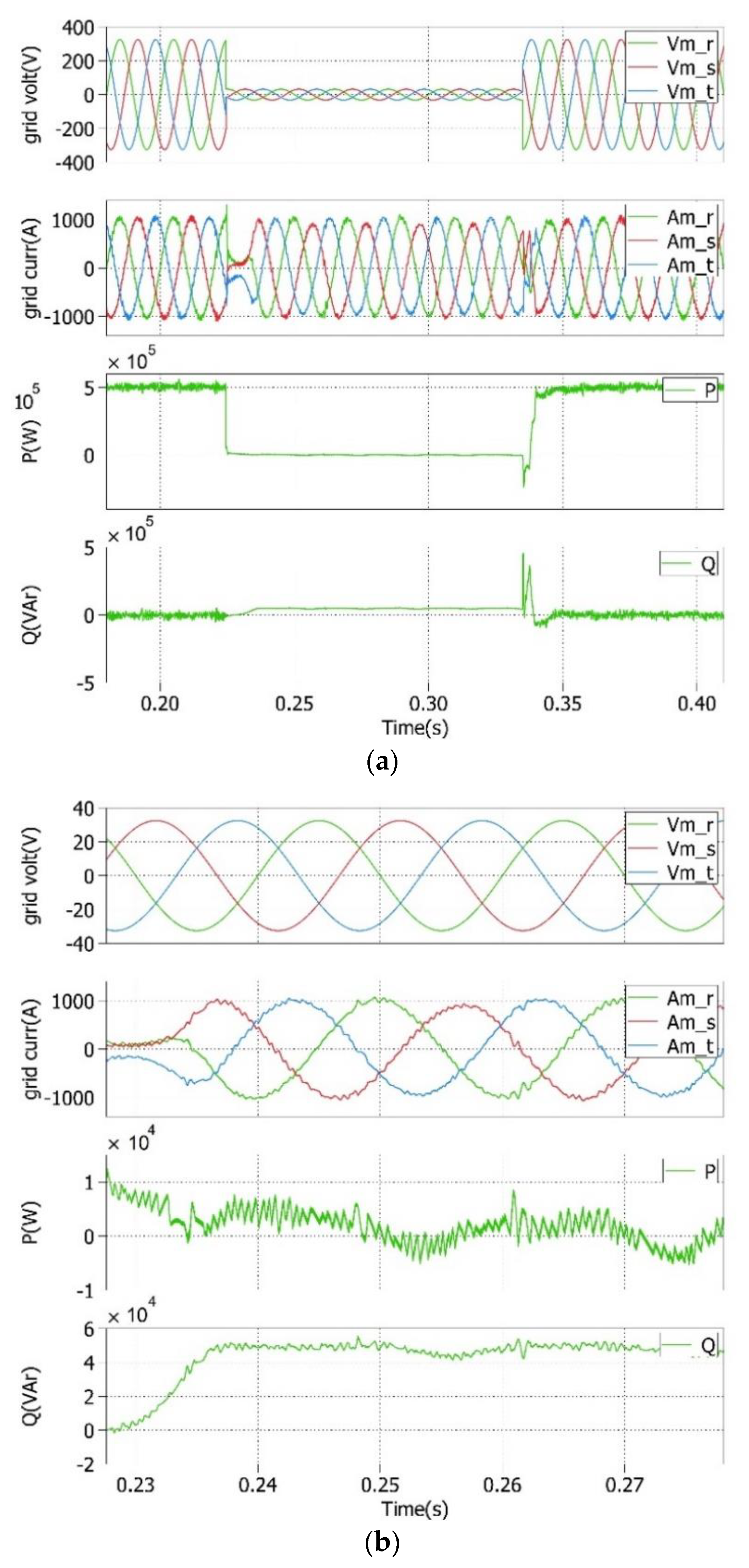
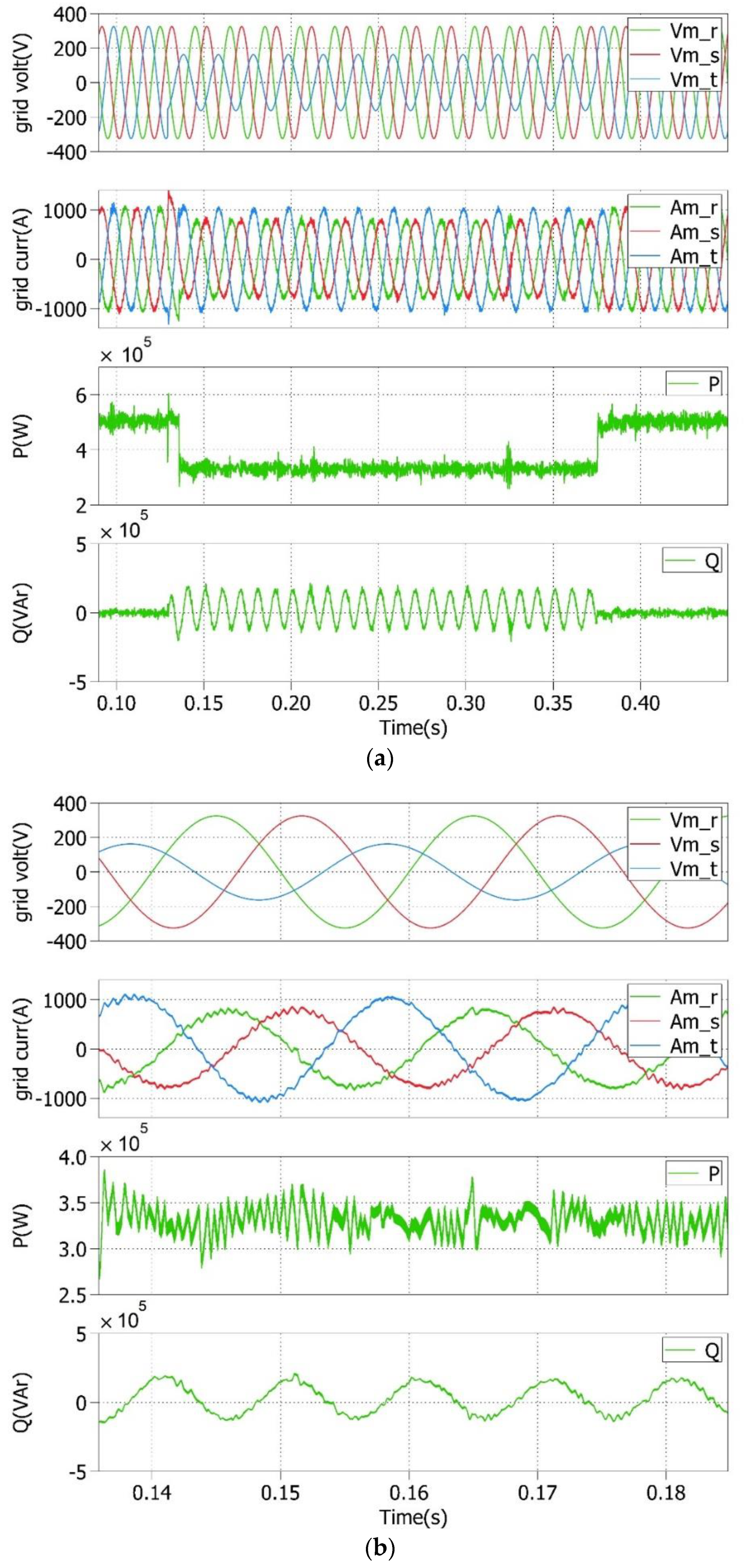
4. Performed Experiments and Results

In the following section, the realized case study, as well as the performed experiments and achieved results, are introduced and discussed.

4.1. Realized Case Study

Table 1 and Table 2 provide an overview of the power and control subsystem parameters that were used in the following experiments employing the well-known controller hardware-in-the-loop (CHIL) validation approach [10,33]. For this, the model of the plant (including the VSI) and the control algorithms were run in real time in a digital real-time simulator (DRTS) and the real microcontroller used in the final prototype, respectively. All the parameters for both tables are referred to in Figure 1, whereas the physical meaning of the parameters for the non-ideal PR regulators are described in detail in [21].
The step sizes for the DRTS and the microcontroller were TS = 5.1196 μs and TREG = 40.9568 μs, respectively. Moreover, the inverse of the switching frequency (fsw) had the same value as TREG for the synchronization between the sample time of the three-phase currents through the inverter and the digital PWM. The resulting controller delay was 3 2 T R E G = 61.44   μ s for the worst case [34].

4.2. Performed Experiments

The CHIL approach is usually more realistic rather than pure software simulations because some effects such as the quantization error of the analog-to-digital converters (ADCs), the sample delays, and the dead-time of the power switches on the inverter (not seen in the latter) are considered. For the performed experiments and tests in this work, a PLECS RT Box [35] was used for the DRTS [36,37,38], together with a TMS320F28379D Dual-Core Delfino Microcontroller [39] as the controller [40]. Although an ideal model for the inverter was used in this work, the switching power losses of a SKM350MB120SCH17 power module employed [41] in a future prototype were estimated around 2436 W for a switching frequency (fSW) of 24.416 kHz, attaining an efficiency of more than 99%.
For the implementation of the grid-connected system with the CHIL experimentation approach, overall, six analog signals at the output of the DRTS were needed: three signals for the utility grid voltages, as well as three signals for the inverter currents, as depicted in Figure 1. Moreover, three digital signals were delivered to the DRTS from the PWM peripheral of the microcontroller to trigger the power switches of the three-phase VSI and to close the current control loop. The resulting block diagram of the used CHIL simulation testbench is shown in Figure 4.
For the evaluation of the proposed LVRT control algorithm, the following three different types of voltage sag were used:
  • A symmetrical (balanced) sag of 90% amplitude;
  • An asymmetrical (unbalanced) sag of 90% amplitude of phase three;
  • An asymmetrical (unbalanced) sag of 50% amplitude of phase three.
For all the cases shown below in the corresponding figures, the time evolution of the three-phase voltages and currents through the mains, as well as the delivered P and Q, are depicted in the upper parts and are denoted as (a), whereas these variables during a fault event (i.e., where the LVRT capability was activated) are depicted in the lower parts and are denoted as (b). The latter was known as the faulty operating conditions where some amount of Q was delivered to the mains according to Equation (8) to improve the grid voltage profile during the occurrence of a voltage sag; the amplitude of the three-phase currents through the inverter must be limited to its nominal value to prevent the inverter from disconnection from the mains during the voltage sag, as said before.
The time evolution of the variables during a symmetrical deep voltage sag of 90% in amplitude is depicted in Figure 5. No NS value of the mains appeared in this case, so P and Q had constant values, whereas three-phase-balanced currents limited to their nominal values were achieved. During the faulty operating conditions, the currents through the mains lagged the voltages by 90°, which means that a zero PF of the system was attained. In this case, zero P and Q = 50 kVAr were delivered to the mains to improve the voltage profile. On the contrary, in normal operating conditions, the three-phase voltages and currents were synchronized in phase and frequency, achieving a unity PF connection (Q* = 0); meanwhile, the maximum available active power (P* = 500 kW) was injected into the mains.
In addition, Figure 6 shows the same variables when an asymmetrical deep voltage sag of 90% occurred in the amplitude of the grid voltage in phase three, whereas Figure 7 depicts the same case during an asymmetrical moderate voltage sag of 50%, also in the amplitude of the grid voltage in phase three. In both situations, the voltage fault in phase three generated oscillations in Q at 2ω0 due to the NS value of the three-phase voltages under unbalanced faults. Hence, a constant P was delivered to the grid. During the occurrence of a voltage sag, for the former case P ≈ 100 kW, and the mean value of Q ≈ 180 kVAr; for the latter case, P ≈ 350 kW, and the mean value of Q ≈ 17.5 kVAr.
Nevertheless, when a constant active power was attained, the sinusoidal three-phase currents through the mains were unbalanced, but its amplitude was also limited to its nominal value, avoiding the disconnection of the inverter from the mains due to the activation of overcurrent protection.

5. Discussion and Conclusions

In this work, an enhanced control concept for a grid-connected renewable energy system was proposed that was capable of delivering a constant active power to the mains during faulty operating conditions. This prevented the destruction of the potential link capacitor due to the large oscillations of the DC link voltage at twice the system frequency if unbalanced voltage sags happened. Also, a certain amount of instantaneous reactive power was delivered to the mains to improve its voltage profile. For this, the proper detection of the positive- and negative-sequence component values of the three-phase voltages of the mains, expressed on the αβ axes, as well as the measurement of their frequency, must be carried out by the synchronization algorithm. Through these PS and NS values, together with the active and reactive power reference commands, the current references generator block was able to calculate the proper reference current commands on the αβ axes for the specified behavior, and the current control was exerted with two PR regulators. A dual second-order generalized integrator frequency-locked loop synchronization algorithm was applied in this work, and the aforementioned variables were properly computed, feeding back the estimated frequency to these regulators.
The amplitudes of the currents through the inverter—for both the faulty and normal operating conditions—were always limited to their nominal values, preventing the disconnection of the inverter from the mains due to overcurrent protection. It has to be noted that these results could be applied to any grid-connected energy system under asymmetrical voltage sags.
The proper behavior of the LVRT algorithm according to IEC 61400-21 and the Spanish grid code was tested for the enhanced control algorithm of the three-phase grid-connected renewable system under different types of grid voltage sags. Hence, the proposed methodology can be easily adapted to any other standard.
Both the constant active power control and the limitation in the amplitude of the currents through the inverter in normal and faulty operating conditions were the main contributions of this work. The results of the CHIL-simulation-based validation showed the applicability of the proposed approach under realistic conditions.

Author Contributions

A.B.R.-B. and N.F.G.-R. developed the control approach and implemented the prototype; J.S. and T.I.S. provided the CHIL-based validation environment and supported A.B.R.-B. and N.F.G.-R. in the corresponding validation work; A.B.R.-B. and N.F.G.-R. wrote the main parts of the paper; J.S. and T.I.S. provided input for the validation part of the paper; and all authors reviewed the paper. All authors have read and agreed to the published version of the manuscript.

Funding

This work received funding from the Spanish Government under the project “Nuevas topologías para convertidores en MT para grandes Instalaciones Fotovoltaicas” (ref. TEC2016-80136-P, A. B. Rey-Boué), as well as from the European Community’s Horizon 2020 Program (H2020/2014-2020) under project “ERIGrid” (grant agreement no. 654113) via the Transnational Access (TA) programme (Ref. ERIGrid TA 04.003-2018 “PVGRIDHIL”).

Conflicts of Interest

The authors declare no conflict of interest.

Nomenclature

Acronyms
ADCAnalog-to-digital converter
CHILController hardware-in-the-loop
CRGCurrent references generator
DGDistributed generator
DERDistributed energy resources
DFIGDoubly fed induction generators
DRTSDigital real-time simulator
DSOGI-FLLDual second-order generalized integrator FLL
FLLFrequency-locked loop
LVRTLow-voltage ride-through
MMCModular multilevel converter
MPCModel predictive control
MPPMaximum power point
MPPTMaximum power point tracking
MSOGI-FLLMultiple second-order generalized integrator FLL
non-MPPTNon-maximum power point tracking
NSNegative-sequence component
PCCPoint of common coupling
PFPower factor
PLLPhase-locked loop
PRProportional resonant
PSPositive-sequence component
PVPhotovoltaic
PWMPulse width modulation
RSCRotor-side converter
SRFSynchronous reference frame
VSIVoltage source inverter
Symbols
c(t)Carrier signal of the PWM
fCICrossover frequency of the current loop
fswSwitching frequency
iuvwthree-phase currents through the inverter
igrstthree-phase currents delivered to the mains
i*αβ±αβ reference commands of the PS and the NS values of the instantaneous three-phase currents through the inverter
i*αβP(Q)αβ reference commands of P (Q) of the instantaneous three-phase currents through the inverter
iDCDC current at the input of the VSI
iαβαβ components of the instantaneous three-phase currents through the inverter
iαβ*αβ reference commands of the instantaneous three-phase currents through the inverter
KIαβ(KPαβ)Integral (proportional) constant of the PR regulators
KPWMGain of the three-phase VSI
LInductance of the L filter
mabc(t)Three-phase modulating signals of the PWM
mαβαβ components of the three-phase modulating signals of the PWM
P(Q)Instantaneous active (reactive) power in normal operating conditions
P*(Q*)Reference command for P(Q)
Q*normalReference command for the normal reactive power
P0 (Q0)Average active (reactive) power
P0− (Q0−)NS values of the average active (reactive) power
P0+ (Q0+)PS values of the average active (reactive) power
Pfault (Qfault)Instantaneous active (reactive) power during voltage sags conditions (or faulty operating conditions)
PmaxMaximum active power delivered to the mains
P*maxReference command of Pmax
P ˜   ( Q ˜ ) Oscillating active (reactive) power at 2ω0
PMIPhase margin of the current loop
TSStep size of the power subsystem
TREGStep size of the control subsystem
SfaultMaximum apparent power during voltage sags conditions (or faulty operating conditions)
SnomNominal apparent power
ug(αβ)αβ components of the instantaneous three-phase grid voltages
ug(αβαβ components of the instantaneous PS and NS values of the three-phase grid voltages
ugnomNominal root-mean-square (rms) value of the phase-to-neutral three-phase grid voltages
ugrstInstantaneous values of the phase-to-neutral three-phase grid voltages (the mains)
VfaultNormalized depth of the voltage sag
ZImpedance of the mains
ω0Fundamental nominal frequency
ω0Estimated frequency of the mains
ωoResonant angular frequency of the PR regulator
ωcCut-off frequency of the PR regulator

References

  1. Meyer, R.; Zlotnik, A.; Mertens, A. Fault Ride-Through Control of Medium-Voltage Converters with LCL Filter in Distributed Generation Systems. IEEE Trans. Ind. Appl. 2014, 50, 3448–3456. [Google Scholar] [CrossRef]
  2. Habib, A.; Sou, C.; Hafeez, H.M.; Arshad, A. Evaluation of the Effect of High Penetration of Renewable Energy Sources (RES) on System Frequency Regulation Using Stochastic Risk Assessment Technique (an Approach Based on Improved Cumulant). Renew. Energy 2018, 127, 204–212. [Google Scholar] [CrossRef]
  3. Al-Shetwi, A.Q.; Sujod, M.Z. Modeling and Control of Grid-Connected Photovoltaic Power Plant With Fault Ride-Through Capability. J. Sol. Energy Eng. 2017, 140, 021001. [Google Scholar] [CrossRef] [Green Version]
  4. Etxegarai, A.; Eguia, P.; Torres, E.; Buigues, G.; Iturregi, A. Current Procedures and Practices on Grid Code Compliance Verification of Renewable Power Generation. Renew. Sustain. Energy Rev. 2017, 71, 191–202. [Google Scholar] [CrossRef]
  5. Luo, X.; Wang, J.; Wojcik, J.D.; Wang, J.; Li, D.; Draganescu, M.; Li, Y.; Miao, S. Review of Voltage and Frequency Grid Code Specifications for Electrical Energy Storage Applications. Energies 2018, 11, 1070. [Google Scholar] [CrossRef] [Green Version]
  6. Robles, E.; Haro-Larrode, M.; Santos-Mugica, M.; Etxegarai, A.; Tedeschi, E. Comparative Analysis of European Grid Codes Relevant to Offshore Renewable Energy Installations. Renew. Sustain. Energy Rev. 2019, 102, 171–185. [Google Scholar] [CrossRef]
  7. Dehghani Tafti, H.; Maswood, A.I.; Konstantinou, G.; Pou, J.; Kandasamy, K.; Lim, Z.; Ooi, G.H.P. Low-Voltage Ride-Thorough Capability of Photovoltaic Grid-Connected Neutral-Point-Clamped Inverters with Active/Reactive Power Injection. IET Renew. Power Gener. 2017, 11, 1182–1190. [Google Scholar] [CrossRef]
  8. Oon, K.H.; Tan, C.K.; Bakar, A.H.A.; Che, H.S.; Mokhlis, H.; Illias, H.A. Establishment of Fault Current Characteristics for Solar Photovoltaic Generator Considering Low Voltage Ride through and Reactive Current Injection Requirement. Renew. Sustain. Energy Rev. 2018, 92, 478–488. [Google Scholar] [CrossRef]
  9. Huka, G.B.; Li, W.; Chao, P.; Peng, S. A Comprehensive LVRT Strategy of Two-Stage Photovoltaic Systems under Balanced and Unbalanced Faults. Int. J. Electr. Power Energy Syst. 2018, 103, 288–301. [Google Scholar] [CrossRef]
  10. Todorović, I.; Grabić, S.; Ivanović, Z. Grid-Connected Converter Active and Reactive Power Production Maximization with Respect to Current Limitations during Grid Faults. Int. J. Electr. Power Energy Syst. 2018, 101, 311–322. [Google Scholar] [CrossRef]
  11. Cupertino, A.F.; Xavier, L.S.; Brito, E.M.S.; Mendes, V.F.; Pereira, H.A. Benchmarking of Power Control Strategies for Photovoltaic Systems under Unbalanced Conditions. Int. J. Electr. Power Energy Syst. 2019, 106, 335–345. [Google Scholar] [CrossRef]
  12. Talha, M.; Raihan, S.R.S.; Rahim, N.A. PV Inverter with Decoupled Active and Reactive Power Control to Mitigate Grid Faults. Renew. Energy 2020, 162, 877–892. [Google Scholar] [CrossRef]
  13. Islam, M.R.; Hasan, J.; Shipon, M.R.R.; Sadi, M.A.H.; Abuhussein, A.; Roy, T.K. Neuro Fuzzy Logic Controlled Parallel Resonance Type Fault Current Limiter to Improve the Fault Ride through Capability of DFIG Based Wind Farm. IEEE Access 2020, 8, 115314–115334. [Google Scholar] [CrossRef]
  14. Ali, M.A.S.; Mehmood, K.K.; Baloch, S.; Kim, C.H. Modified Rotor-Side Converter Control Design for Improving the LVRT Capability of a DFIG-Based WECS. Electr. Power Syst. Res. 2020, 186, 106403. [Google Scholar] [CrossRef]
  15. Mei, H.; Jia, C.; Fu, J.; Luan, X. Low Voltage Ride through Control Strategy for MMC Photovoltaic System Based on Model Predictive Control. Int. J. Electr. Power Energy Syst. 2021, 125, 106530. [Google Scholar] [CrossRef]
  16. Karimi-Ghartemani, M.; Iravani, M.R. A Method for Synchronization of Power Electronic Converters in Polluted and Variable-Frequency Environments. IEEE Trans. Power Syst. 2004, 19, 1263–1270. [Google Scholar] [CrossRef]
  17. Rodríguez, P.; Pou, J.; Bergas, J.; Candela, J.I.; Burgos, R.P.; Boroyevich, D. Decoupled Double Synchronous Reference Frame PLL for Power Converters Control. IEEE Trans. Power Electron. 2007, 22, 584–592. [Google Scholar] [CrossRef]
  18. Rodriguez, P.; Luna, A.; Ciobotaru, M.; Teodorescu, R.; Blaabjerg, F. Advanced Grid Synchronization System for Power Converters under Unbalanced and Distorted Operating Conditions. In Proceedings of the IECON 2006—32nd Annual Conference on IEEE Industrial Electronics, Paris, France, 6–10 November 2006; IEEE: Piscataway, NJ, USA, 2006; pp. 5173–5178. [Google Scholar]
  19. Rodríguez, P.; Luna, A.; Candela, I.; Mujal, R.; Teodorescu, R.; Blaabjerg, F. Multiresonant Frequency-Locked Loop for Grid Synchronization of Power Converters under Distorted Grid Conditions. IEEE Trans. Ind. Electron. 2011, 58, 127–138. [Google Scholar] [CrossRef] [Green Version]
  20. Rey-Boué, A.B.; Guerrero-Rodríguez, N.F.; Stöckl, J.; Strasser, T.I. Modeling and Design of the Vector Control for a Three-Phase Single-Stage Grid-Connected PV System with LVRT Capability According to the Spanish Grid Code. Energies 2019, 12, 2899. [Google Scholar] [CrossRef] [Green Version]
  21. Guerrero-Rodríguez, N.F.; Rey-Boué, A.B. Modelling, Simulation and Experimental Verification for Renewable Agents Connected to a Distorted Utility Grid Using a Real-Time Digital Simulation Platform. Energy Convers. Manag. 2014, 84, 108–121. [Google Scholar] [CrossRef]
  22. Díaz, M.; Cárdenas, R.; Wheeler, P.; Clare, J.; Rojas, F. Resonant Control System for Low-Voltage Ride-through in Wind Energy Conversion Systems. IET Power Electron. 2016, 9, 1297–1305. [Google Scholar] [CrossRef]
  23. IEC 61400-21:2008|IEC Webstore|Rural Electrification, Wind Power. Available online: https://webstore.iec.ch/publication/5434 (accessed on 14 January 2019).
  24. Afshari, E.; Moradi, G.R.; Rahimi, R.; Farhangi, B.; Yang, Y.; Blaabjerg, F.; Farhangi, S. Control Strategy for Three-Phase Grid-Connected PV Inverters Enabling Current Limitation under Unbalanced Faults. IEEE Trans. Ind. Electron. 2017, 64, 8908–8918. [Google Scholar] [CrossRef] [Green Version]
  25. Camacho, A.; Castilla, M.; Miret, J.; Borrell, A.; de Vicuna, L.G. Active and Reactive Power Strategies with Peak Current Limitation for Distributed Generation Inverters during Unbalanced Grid Faults. IEEE Trans. Ind. Electron. 2015, 62, 1515–1525. [Google Scholar] [CrossRef] [Green Version]
  26. Rodriguez, P.; Timbus, A.V.; Teodorescu, R.; Liserre, M.; Blaabjerg, F. Flexible Active Power Control of Distributed Power Generation Systems during Grid Faults. IEEE Trans. Ind. Electron. 2007, 54, 2583–2592. [Google Scholar] [CrossRef]
  27. Teodorescu, R.; Liserre, M.; Rodríguez, P. Grid Converters for Photovoltaic and Wind Power Systems; John Wiley & Sons, Inc.: Hoboken, NJ, USA, 2011; ISBN 9781119957201. [Google Scholar]
  28. Teodorescu, R.; Blaabjerg, F.; Liserre, M.; Loh, P.C. Proportional-Resonant Controllers and Filters for Grid-Connected Voltage-Source Converters. IEE Proc. Electr. Power Appl. 2006, 153, 750. [Google Scholar] [CrossRef] [Green Version]
  29. Circuit Analysis of A-c Power Systems Vol. I: Shoults D.R: Free Download, Borrow, and Streaming: Internet Archive. Available online: https://archive.org/details/in.ernet.dli.2015.1252/page/n5 (accessed on 31 January 2019).
  30. Wang, Y.; Yang, P.; Yin, X.; Ma, Y. Evaluation of Low-Voltage Ride-through Capability of a Two-Stage Grid-Connected Three-Level Photovoltaic Inverter. In Proceedings of the 2014 17th International Conference on Electrical Machines and Systems, ICEMS, Hangzhou, China, 22–25 October 2014; IEEE: Piscataway, NJ, USA, 2015; pp. 822–828. [Google Scholar]
  31. Akagi, H.; Watanabe, E.H.; Aredes, M. Instantaneous Power Theory and Applications to Power Conditioning; John Wiley & Sons, Inc.: Hoboken, NJ, USA, 2017; ISBN 9781119307181. [Google Scholar]
  32. Energinet, D. Technical Regulation 3.2 2 for PV Power Plants with a Power Output above 11 KW; Energinet: Fredericia, Denmark, 2015; pp. 1–96. [Google Scholar]
  33. Faulstich, A.; Stinke, J.K.; Wittwer, F. Medium Voltage Converter for Permanent Magnet Wind Power Generators up to 5 MW. In Proceedings of the 2005 European Conference on Power Electronics and Applications, Dresden, Germany, 11–14 September 2005; IEEE: Piscataway, NJ, USA, 2005; p. 9. [Google Scholar]
  34. Buso, S.; Mattavelli, P. Digital Control in Power Electronics; Morgan & Claypool Publishers: San Rafael, CA, USA, 2006; Volume 1, ISBN 9781598291124. [Google Scholar]
  35. Electrical Engineering Software Plexim. Available online: https://www.plexim.com/ (accessed on 14 January 2019).
  36. Omar Faruque, M.D.; Strasser, T.; Lauss, G.; Jalili-Marandi, V.; Forsyth, P.; Dufour, C.; Dinavahi, V.; Monti, A.; Kotsampopoulos, P.; Martinez, J.A.; et al. Real-Time Simulation Technologies for Power Systems Design, Testing, and Analysis. IEEE Power Energy Technol. Syst. J. 2015, 2, 63–73. [Google Scholar] [CrossRef]
  37. Guillaud, X.; Faruque, M.O.; Teninge, A.; Hariri, A.H.; Vanfretti, L.; Paolone, M.; Dinavahi, V.; Mitra, P.; Lauss, G.; Dufour, C.; et al. Applications of Real-Time Simulation Technologies in Power and Energy Systems. IEEE Power Energy Technol. Syst. J. 2015, 2, 103–115. [Google Scholar] [CrossRef] [Green Version]
  38. Benigni, A.; Strasser, T.; De Carne, G.; Liserre, M.; Cupelli, M.; Monti, A. Real-Time Simulation-Based Testing of Modern Energy Systems: A Review and Discussion. IEEE Ind. Electron. Mag. 2020, 14, 28–39. [Google Scholar] [CrossRef]
  39. Analog, Embedded Processing, Semiconductor Company, Texas Instruments—TI.Com. Available online: http://www.ti.com/# (accessed on 14 January 2019).
  40. Jonke, P.; Stockl, J.; Miletic, Z.; Brundlinger, R.; Seitl, C.; Andren, F.; Lauss, G.; Strasser, T. Integrated Rapid Prototyping of Distributed Energy Resources in a Real-Time Validation Environment. In Proceedings of the 2016 IEEE 25th International Symposium on Industrial Electronics (ISIE), Santa Clara, CA, USA, 8–10 June 2016; IEEE: Piscataway, NJ, USA, 2016; pp. 714–719. [Google Scholar]
  41. SKM350MB120SCH17 SEMIKRON. Available online: https://www.semikron.com/de/produkte/produktklassen/sic/voll-sic-module/detail/skm350mb120sch17-21920420.html (accessed on 10 February 2020).
Figure 1. The grid-connected renewable energy system.
Electronics 11 01404 g001
Figure 2. (a) LVRT requirements according to the IEC 61400-21 standard [22,23] and (b) proper Q delivered to the utility grid according to the normalized depth of voltage sags from the example of Spain ( Δ V   ( pu ) = 1 V f a u l t ) [24].
Electronics 11 01404 g002
Figure 3. Flowchart of the proposed low-voltage ride-through control algorithm.
Electronics 11 01404 g003
Figure 4. CHIL simulation testbench.
Electronics 11 01404 g004
Figure 5. (a) Grid voltages and currents instantaneous active (P) and reactive (Q) powers during a symmetrical deep voltage sag of 90%; (b) detailed view during the faulty operating condition.
Electronics 11 01404 g005
Figure 6. (a) Grid voltages, currents, and P and Q during an asymmetrical deep voltage sag of 90% in phase 3; (b) detailed view during the faulty operating conditions.
Electronics 11 01404 g006
Figure 7. (a) Grid voltages, currents, and P and Q during an asymmetrical moderate voltage sag of 50% in phase 3; (b) detailed view during the faulty operating conditions.
Electronics 11 01404 g007
Table 1. Power subsystem parameters (VDC = 800 V).
ParametersValue
Inverter Gain KPWM 2 3 v D C
Switching frequency fsw24.416 kHz
Line inductance L0.15 mH
Mains (AC system ugrst)230 Vrms phase-to-neutral, 50 Hz
Table 2. Control subsystem parameters (fCI = 610.4 Hz, PMI = 63.5°).
Parameters of the PR RegulatorValue
Proportional constant KPαβ0.0011
Integral constant KIαβ0.1
Resonant angular frequency ωo314.16 rad/s
Cutoff frequency ωc1 rad/s
Publisher’s Note: MDPI stays neutral with regard to jurisdictional claims in published maps and institutional affiliations.

