Article

A Novel Metasurface Lens Design for Synthesizing Plane Waves in Millimeter-Wave Bands

1
China Academy of Information and Communications Technology, Beijing 100191, China
2
School of Electronic Engineering, Beijing University of Posts and Telecommunications, Beijing 100876, China
3
School of Information Engineering, Zhengzhou University, Zhengzhou 450001, China
*
Author to whom correspondence should be addressed.
Electronics 2022, 11(9), 1403; https://doi.org/10.3390/electronics11091403
Submission received: 31 March 2022 / Revised: 13 April 2022 / Accepted: 16 April 2022 / Published: 27 April 2022
(This article belongs to the Special Issue EMC Analysis in Wireless Communication)

Abstract

:
With the development of communication technology has come several measurement applications requiring plane-wave conditions for wireless-device characterizations in anechoic chambers. In this paper, a metasurface lens with a 2 × 2 feeding-antenna array is proposed and characterized to synthesize a plane wave in a near field for a fifth-generation (5G) millimeter-wave radio-frequency (RF) devices test. The metasurface lens, based on Jerusalem-cross elements printed on a printed circuit board (PCB) substrate, is used for controlling the phase-shift distribution of incident spherical waves. The lens has a size of 0.4 × 0.4 m and is designed to operate at a range from 24.25 GHz to 27.5 GHz, and its feeding-antenna array is located at a focal plane of the lens, which is parallel to the metasurface lens. The lens is studied and verified through simulations and experiments, and a uniform amplitude and phase-field distribution at a reduced distance of 1.2 m generated by the metasurface lens throughout a QZ are achieved. The worst-case amplitude and phase variation of the designed metasurface lens are ±0.75 dB and ±7.5°, respectively. The results show a plane-wave condition can be achieved in 5G millimeter bands through the proposed compact and effective metasurface lens. Moreover, the proposed metasurface lens is shown to be capable of reducing the plane-wave synthesizing distance compared to the compact antenna test range (CATR) with a significantly reduced system cost, making it an attractive alternative to antenna testing in 5G millimeter-wave frequency bands.

1. Introduction

In recent years, 5G technology has been implemented and developed on a large scale. More specifically, 5G systems at frequency range two (FR2) have improved the channel capacities of systems by using the large bandwidths of millimeter waves [1,2,3]. Due to demands for higher data rates and increasing user terminals, massive multiple-input multiple-output (MIMO) was introduced as one of the key 5G technologies by the third-generation partnership project (3GPP) for a higher spectrum efficiency in real networks. The radio performance of massive MIMO devices should be fully characterized in plane-wave conditions using radiated over-the-air (OTA) test methods [4,5,6]. OTA testing is seen as essential for mm-wave devices due to a highly integrated antenna and transceiver design [7]. In 3GPP, there are several measurement scenarios requiring plane-wave conditions for device characterization: RF conformance with a specific angle of arrival, a simultaneous in-band and out-of-band emission analysis [8], radio resource management (RRM) conformance with different power levels from multiple angles of arrival, mobility management verification [9], and MIMO techniques to accurately reflect wireless propagation conditions [10]. Base stations are located in the far field of 5G millimeter-wave devices, and therefore, the electromagnetic waves from base stations can be recognized as plane waves, which can be recognized as real-world conditions.
A far field is typically defined as beyond the Fraunhofer distance:
R = 2 D 2 λ ,
where D is the maximum aperture of a device under test (DUT) and λ is the wavelength. By placing a probe antenna in the far field of a DUT, a plane-wave condition can be achieved and the phase curvature in the QZ is 22.5° [11]. For a typical millimeter-wave device with a dimension of 0.2 m × 0.2 m, the far-field distance is 13.87 m at 26 GHz and the free-space path loss is roughly 83.58 dB with the following formula:
L = 32.4478 + 20 × lg ( f ) + 20 × lg ( d ) ,
where L is the path loss and d represents the distance between the transmitter and receiver. With such a measurement distance, an anechoic chamber is expensive to construct and impractical for measuring low-power emissions due to a high signal attenuation introduced by the long measurement distance.
It is convenient and essential to carry out OTA measurements at distances that are significantly shorter than the Fraunhofer distance. The near-field to far-field (NF-FF) method was proposed for drastically reducing the measurement distance, and it can be used in passive antenna measurements. The NF-FF method [12] usually uses planar, cylinder, or spherical scanning in a near field to measure the phase and amplitude distributions of a device. Then, a NF-FF transformation [13] is applied to compute a far-field pattern. However, for modulated 5G millimeter-wave devices, cabled connections do not exist, and it would be technically problematic to derive the modulated far-field measurement results from power measurements. Therefore, the new-method plane-wave generator (PWG) using an active probe array to create a uniform plane wave over a QZ in a near field was proposed [14].
By designing the weights of amplitudes and phases on each probe, a plane wave with an acceptable deviation at a given distance from a PWG can be achieved [15]. In addition, in order to control the phase and amplitude of every probe, a large number of high-precision phase shifters is needed, and they are expensive and immature in a millimeter frequency band. Therefore, the compact-antenna test-range (CATR) technique was proposed to be used in high frequency measurements. The CATR [16] technique establishes a feeding antenna on the focal plane of a paraboloid reflector, which converts a spherical wave transmitted from the feeding antenna into a plane wave over a QZ and reduces the electromagnetic wave-propagation distance to compensate for the free-space path loss. Furthermore, the QZ is typically half the size of the reflector, and the upper frequency limit of the CATR depends on the surface smoothness, which needs careful manufacturing and maintenance, especially at millimeter frequency bands [17]. To avoid these problems in the CATR’s setup, reducing the measurement distance, a compact and cost effective solution based on a metasurface lens, is introduced in this work. Metasurface lenses based on a Jerusalem-cross structure have been widely used for higher gain antennas with low sidelobes at sub-6 GHz, and most of them have not been integrated with antennas [18,19,20,21,22,23]. In [24], a very small focal-to-diameter (F/D) ratio transmitarray for generating a high-quality QZ at 2.6 GHz was proposed, but few studies have been conducted on millimeter waves. Consequently, further research on feed antenna and metasurface lens designs aimed at generating a large and high quality QZ at millimeter frequency bands for wireless device testing is needed.
In this paper, to create a uniform plane wave and to further reduce the cost and size of the test system, a metamaterial metasurface lens fed by a planar 2 × 2 patch-antenna array is proposed for synthesizing plane waves in millimeter wave bands at a reduced distance. The metasurface lens, based on frequency-selective surface (FSS) structures, is designed to achieve a phase-shift distribution of incident spherical waves from a patch-antenna array so that the metasurface lens can realize wave control. The planar 2 × 2 patch-antenna array is proposed to maximize the uniformity of illumination over some portions of the FSS structure whilst providing the field intensity windowing needed to minimize edge-diffraction effects, thereby enabling greater aperture efficiency to be achieved for a given QZ size. Traditionally, the PWG excitation weight is implemented with the aid of a programmable phase shifter or power dividers and programmable attenuators, but the plane-wave condition synthesized by the metasurface lens is realized through the geometry, dimensions, and periodicity of the proposed FSS structure. With the advantages of compactness, a low cost and a small space loss, the proposed metasurface lens can be an alternative to synthesizing plane waves in millimeter wave bands.
The major contributions of this paper are summarized into three points.
(1)
A novel design based on a metasurface lens for generating a plane-wave condition in a reduced distance is introduced; it can be a cost-effective solution for mm-wave PWG systems.
(2)
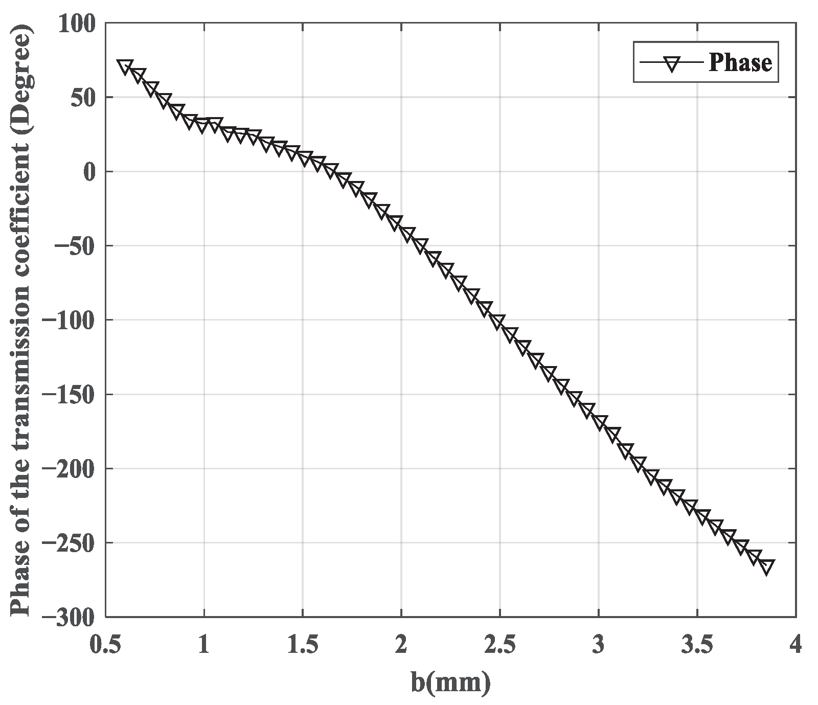
The performance of the phase-shift element is investigated in millimeter wave bands; it can be used to replace expensive and inaccurate millimeter phase shifters.
(3)
The designed metasurface lens, working at a frequency range from 24.25 GHz to 27.5 GHz, is validated through simulations and experiments. The results show that a uniform amplitude and phase can be achieved.
The rest of the paper is organized as follows. The proposed metasurface lens’s geometry is described in Section 2. The principle and simulation of the metasurface lens’s synthesizing plane wave are described in Section 3. The characterization and validation results of the metasurface lens are described in Section 4. A summary and conclusion are given in Section 5.

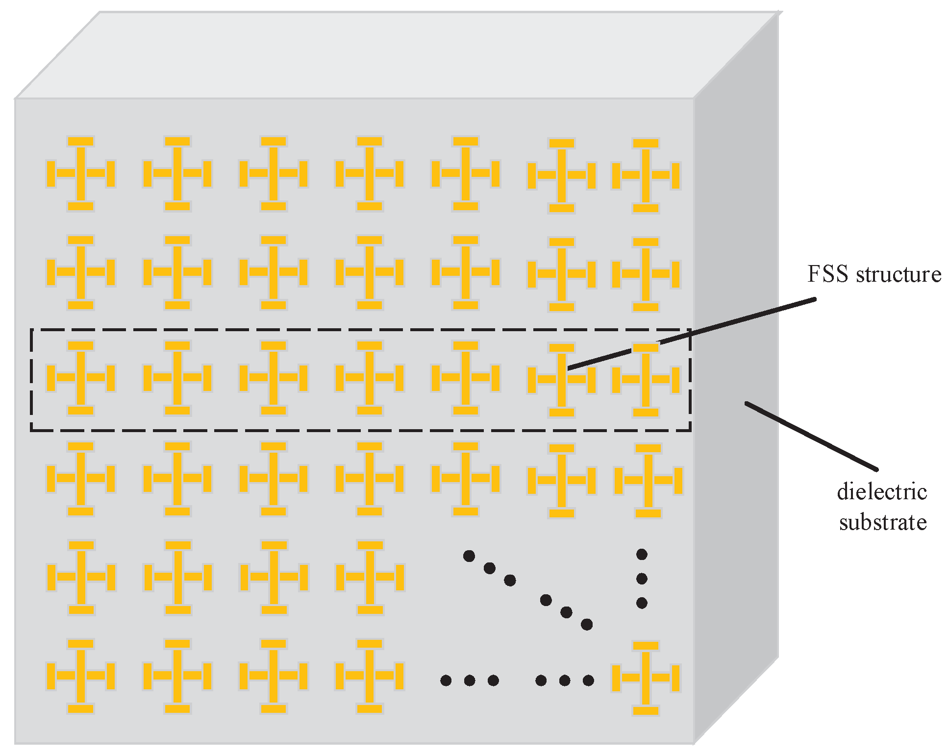
2. Geometry of Metasurface Lens

The metasurface lens, as shown in Figure 1, is composed of a resonant metal layer and a dielectric substrate layer. The resonant metal layer is an FSS structure printed on top of the intermediate dielectric substrate, which plays the role of phase shifting. The various dimensions of the resonant metal are designed to achieve different phase shifts forming several annular zones. For one circular annular zone, the resonant metal structure is of the same dimension needed to achieve the same phase delay. To maximize the phase uniformity of illumination over the metasurface lens, the feeding-antenna array is designed to be composed of a 2 × 2 planar dual-polarized patch antenna. A spherical wave from the feeding-antenna array is converted into a plane wave in the vertical and horizontal directions by the metasurface-lens array, which largely reduces the propagation distance and improves the electric-field intensity of the QZ.
In terms of fabrication, the designed metasurface lens was manufactured by employing a chemical-etching facility based in laser direct-imaging (LDI) technology. A copper layer with a thickness of 35 um was employed in this work as the resonant-metal material due to its promising conductivity and ease of fabrication. A PCB layer with a Rogers RO4003C material was chosen as a dielectric substrate layer based on its low absorption and electromagnetic stability in millimeter-wave bands. Moreover, the resolution of fabrication was 0.05 mm for the copper layer and 0.1 mm for the PCB layer, which was important to ensure the QZ quality of the designed area.

3. Metasurface Lens Design

In order to demonstrate its applications to millimeter-wave bands, the metasurface lens and feeding-antenna array aimed at synthesizing plane waves at 26 GHz at a reduced distance from a feed position are discussed in this section. The feasibility of this lens–antenna scenario sets up a demonstration of the applications to millimeter-wave bands and the compactness of the proposed lens antenna as suitable for use in anechoic chambers as a radiated source.

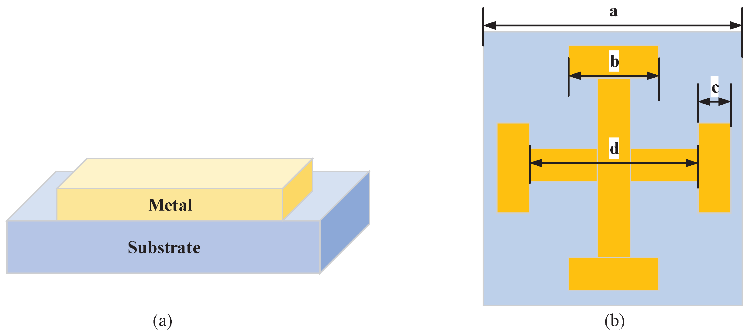
3.1. Phase-Shift Element

The FSS structure shown in Figure 2a is the proposed metasurface lens’s phase-shift element, for which a periodic metallic array was designed on the top side of the dielectric substrate. The metal layer was assumed to be a perfect electric conductor, and the substrate was modeled as a low-absorption material. The geometry of the phase-shift element is illustrated in Figure 2b, where symmetrical copper Jerusalem-cross elements are printed on the Rogers RO4003C substrate with a relative permittivity of 3.38 in the metasurface-lens design. The Rogers substrate was used because it exhibits a very low absorption loss and small refractive-index variations in millimeter-wave bands. The metal layer for the design was chosen to be 35 um-thick copper and the dielectric substrate was 1.524 mm-thick PCB; the detailed dimensions of the phase-shift element are listed in Table 1.
In order to investigate the millimeter transmission response of the designed FSS structure, the finite-difference time-domain (FDTD) method was adopted for a simulation. During the simulation modeling, the dielectricity and permeability of the structure were taken into account, and the perfect matched layer conditions were applied to limit the computation domain. The direction of the incident wave was from the copper Jerusalem-cross elements to the Rogers RO4003C substrate; the electric field from the feeding antenna array made electrons oscillate, then an induced current was formed on the metal surface. Furthermore, for the periodic phase-shift element in the metal layer, a small part of the incident millimeter-wave energy maintained the oscillation of electrons, while the other part of the energy continued to spread through the FSS structure. In other words, in certain frequencies, according to the law of conservation of energy, the energy maintaining the electron oscillation was absorbed as a dielectric loss and the other part of the energy was spread through the FSS structure so that the reflection was zero and the frequency was the resonant point. The phase of the transmission coefficient against the side length of the phase-shift element’s length is shown in Figure 3. As b increased from 0.6 to 3.9 mm, the phase delay had a variation range from 0° to 360°, accompanied by an acceptable stable insertion loss. Due to a spherical wave from the feeding-antenna array, the phase changed sharply on the vertical plane at a reduced distance. Therefore, different length elements were arranged in different places on the PCB substrate to compensate for the phase variation, which formed several circular annular zones.

3.2. Metasurface Lens

Different phase-shift elements were provided by the metasurface lens for the radiating wave from the feeding antenna to form a plane wave in a reduced distance. The phase difference between different phase-shift element positions could be determined as follows:
φ i = 2 π λ r i ,
where r i was the distance between focus F and position i, ϕ i represented the phase distribution at position i, and f was the focal length.
As shown in Figure 4, by aiming at achieving a uniform phase distribution in the QZ, the phase compensation provided by phase shift element i could be easily obtained by using:
Δ φ i = φ i 2 π λ 0 f ,
where f was the distance between focus F and position o. According to the phase of the transmission coefficient results, presented in Figure 3, and other oblique incidence scenarios, the dimensions of the phase-shift elements for the corresponding annular zones cold be determined. There were 101 phase-shift elements along the x and y direction, respectively. The metasurface lens was symmetrical in vertical and horizontal directions with a radiating-aperture size of 0.4 m × 0.4 m. The Jerusalem-cross element-based metasurface lens with a pertinent phase shift provided the required phase delay according to Equation (4).

3.3. Feeding-Antenna Array Design

In order to get a better QZ performance, half the power from the feeding antenna array was designed to illuminate on the metasurface lens by adjusting the focal diameter ratio. As shown in Figure 5, a planar array of a 2 × 2 square patch array printed on the Rogers RO4003C substrate was designed to feed the metasurface lens and to demonstrate its performance in plane-wave generator systems. The detailed dimensions of the 2 × 2 square patch array are listed in Table 2.
As depicted in Figure 6a, from 24 GHz to 29 GHz, the reflection coefficient was below −10 dB. The magnitude and phase distribution at the reduced distance of 1.2 m, along with the radiation directions in the E-field of the feeding-antenna array, are presented in Figure 6b. The feeding antenna had a variable phase pattern from −60° to 5° accompanied by a stable magnitude from −52.5 to −53.5 dB, which was regarded, approximately, as the spherical wave. Moreover, the phase varied sharply in the QZ edge, which would result in a non-uniform phase distribution; the metasurface lens was designed as the passive phase shifter for the plane-wave condition.

3.4. Simulated-Array Performance

To illustrate the electric-field intensity coverage capability, the metasurface lens and feeding-antenna array were simulated by using a full-waveform FDTD method, which was modified and developed over the last decades and directly computes the impulse response of an electromagnetic system in a single simulation. In this simulation, the feeding-antenna array was located on the focal plane of the lens, which was parallel to the metasurface lens. The distance between the lens and the feeding-antenna array was 0.45 m, and the metasurface lens was 0.4 m × 0.4 m, corresponding to a focal-diameter ratio of 1.1.
Figure 7 clearly shows a uniform electric-field intensity distribution area forming a circular focusing region at a reduced distance of 1.2 m with respect to the boresight direction when the metasurface lens is illuminated by the feeding-antenna array at a normal incidence. The circular focusing region is the designed QZ, which is perpendicular to the electromagnetic-wave propagation. With the increase of the electromagnetic-wave propagation distance, the phase-shift element of the metasurface lens varies and leads to the circular-focusing region’s enlargement. Meanwhile, an increase in the path loss for the metasurface lens results in a lower magnitude and eventually leads to a limited dynamic range in the QZ area.

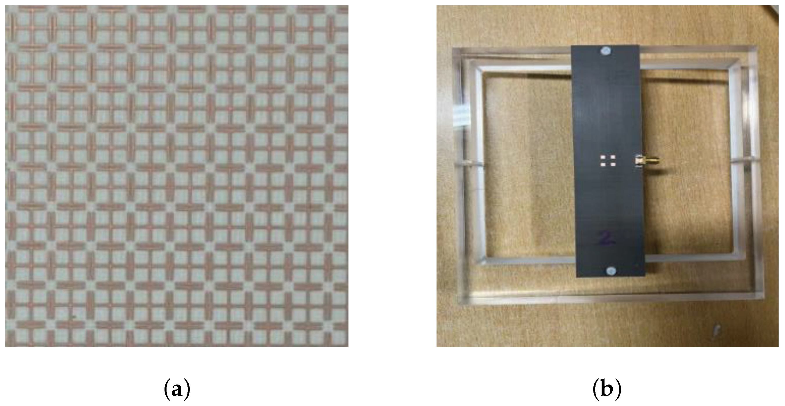
4. Measurements and Discussion

The proposed metasurface lens fed by the planar 2 × 2 patch-antenna array was manufactured and measured to verify its design. A metasurface-lens prototype is exhibited in Figure 8a; the copper Jerusalem-cross patterns are etched onto one side of the Rogers RO4003C substrate with a thickness of 1.524 mm. As shown in Figure 8b, the planar 2 × 2 patch-antenna array located on the focal plane of the metasurface lens was designed as the feeding-antenna array, which was assembled with the metasurface lens using an acrylic supporting structure. The metasurface lens and feeding-antenna array prototypes were both fabricated with LDI technology, which could be printed on ordinary PCB in a modular form and assembled as a flat structure. Figure 9 presents the proposed metasurface lens fed by the planar 2 × 2 patch-antenna array, to which a supporting structure was added to maintain the position of the focus. The distance between the metasurface lens and the feeding-antenna array was 0.4 mm, and the QZ was synthesized at a reduced distance 1.2 m from the feeding-antenna array with respect to the boresight direction.
The amplitude and phase variation of the QZ are considered the dominant performance criteria of a given metasurface lens in the CATR. The field properties were generally characterized as part of a metasurface-lens design using a procedure based upon a field-probe scanner comprising a probe antenna mounted on a linear translation axis. The measured results are shown in Figure 10; due to the physical symmetry of the metasurface lens in the vertical and horizontal directions, the amplitude and phase of the designed QZ are shown along one principal cut over a range of 0.4 m in x direction, which is 1.2 m away from the feeding-antenna array. It can be seen that in the designed 0.2 m QZ, the amplitude taper fulfilled 1 dB and the peak-to-peak amplitude and phase ripples were ±0.75 dB and ±7.5°, respectively. This corresponded to a QZ = 50% of the size of the metasurface lens. Meanwhile, as depicted in Figure 10a–d, probably due to misalignment errors, some slight dis-symmetry occurred in the axis center. In summary, the designed structure printed on a single layer of the Rogers substrate had a wide frequency coverage from 24.25 GHz to 27.5 GHz, which could be used as a practical alternative for RF millimeter user-equipment tests in band N258. This essentially shows that it is possible to generate a relatively large QZ using a metasurface lens fed by an antenna array. Furthermore, in this preliminary design, the metasurface lens was optimized for a 0.2 m × 0.2 m QZ with a 0.4 m × 0.4 m PCB substrate. It is expected that a larger QZ can be achieved with the enlargement of the metasurface lens. These topics should be subject to future investigations and research.

5. Conclusions

This paper describes the design, simulation, and measurement of a novel metasurface lens for millimeter-wave RF tests. The metasurface lens, fed by a planar 2 × 2 feeding-antenna array, was designed for synthesizing plane waves in a near field at millimeter-wave frequency bands. The designed lens antenna was verified in terms of amplitude and phase-field distribution at a reduced distance of 1.2 m through using a simulated FDTD method. Compared with the single feeding-antenna array, the phase-shift capability of the lens significantly reduces the distance needed to synthesize the plane wave. Moreover, the QZ is broadened and the amplitude and phase uniformity are greatly optimized. The designed metasurface lens is manufactured by employing a chemical-etching facility based in LDI technology, and periodic copper Jerusalem-cross patterns are etched onto the PCB substrate. The asymmetry of the lens makes it easy and convenient to fabricate. The above designed metasurface lens was quantified and verified through measurements in an anechoic chamber. A very satisfactory agreement was obtained between experimental and simulated results carried out with a planar scanner. In addition, with the metasurface lens, cost and weight are significantly reduced compared with the CATR. Consequently, the proposed metasurface lens can be a practical alternative for millimeter user-equipment RF and RRM tests in anechoic chambers, which require single and multiple angles of arrival.

Author Contributions

Conceptualization, Y.Z. and Z.W.; methodology, J.Z.; investigation, Z.W. and C.P.; validation, L.J. and X.Z.; writing—original draft preparation, Y.Z.; writing—review and editing, J.Z.; visualization, Y.R. All authors have read and agreed to the published version of the manuscript.

Funding

This research was funded by the National Key Research and Development Program (no. 2020YFB1807401).

Conflicts of Interest

The authors declare no conflict of interest.

References

  1. Chen, X.; Abdullah, M.; Li, Q.; Li, J.; Zhang, A.; Svensson, T. Characterizations of Mutual Coupling Effects on Switch-Based Phased Array Antennas for 5G Millimeter-Wave Mobile Communications. IEEE Access 2019, 7, 31376–31384. [Google Scholar] [CrossRef]
  2. Chen, X.; Abdullah, M.; Zhang, S.; Li, T.; Li, Q. Mutual Coupling Reduction of Slot Array Antenna for 5G Millimeter-wave Handset. In Proceedings of the 2019 Photonics Electromagnetics Research Symposium-Fall (PIERS-Fall), Xiamen, China, 17–20 December 2019; pp. 1525–1530. [Google Scholar] [CrossRef]
  3. Hong, W.; Jiang, Z.H.; Yu, C.; Zhou, J.; Chen, P.; Yu, Z.; Zhang, H.; Yang, B.; Pang, X.; Jiang, M.; et al. Multibeam Antenna Technologies for 5G Wireless Communications. IEEE Trans. Antennas Propag. 2017, 65, 6231–6249. [Google Scholar] [CrossRef]
  4. Gao, H.; Wang, W.; Fan, W.; Wu, Y.; Liu, Y.; Pedersen, G.F. Beam Probability Metric for OTA Testing of Adaptive Antenna Systems in Multi-Probe Anechoic Chamber Setups. In Proceedings of the 2019 13th European Conference on Antennas and Propagation (EuCAP), Krakow, Poland, 31 March–5 April 2019; pp. 1–5. [Google Scholar]
  5. Gao, H.; Wang, W.; Fan, W.; Wu, Y.; Liu, Y.; Pedersen, G.F. Beam Probability Metric for 5G OTA Testing in Multi-Probe Anechoic Chamber Setups. In Proceedings of the 2019 IEEE International Symposium on Antennas and Propagation and USNC-URSI Radio Science Meeting, Atlanta, GA, USA, 7–12 July 2019; pp. 1847–1848. [Google Scholar] [CrossRef]
  6. Cartón Llorente, I.; Fan, W.; Pedersen, G.F. MIMO OTA Testing in Small Multiprobe Anechoic Chamber Setups. IEEE Antennas Wirel. Propag. Lett. 2016, 15, 1167–1170. [Google Scholar] [CrossRef] [Green Version]
  7. Fan, W.; Kyosti, P.; Rumney, M.; Chen, X.; Pedersen, G.F. Over-the-Air Radiated Testing of Millimeter-Wave Beam-Steerable Devices in a Cost-Effective Measurement Setup. IEEE Commun. Mag. 2018, 56, 64–71. [Google Scholar] [CrossRef] [Green Version]
  8. 3GPP TS 38.521-2. User Equipment (UE) Conformance Specification; Radio Transmission and Reception; Part 2: Range 2 Standalone. Technical Specification Release 16, V16.5.0. September. 2020; Available online: https://www.3gpp.org/ftp/Specs/archive/38_series/38.521-2/ (accessed on 24 March 2022).
  9. 3GPP TS 38.533, NR; User Equipment (UE) Conformance Specification; Radio Resource Management (RRM). Technical Specification Release 16, V16.5.0. September 2020. Available online: https://www.3gpp.org/ftp/Specs/archive/38_series/38.533/ (accessed on 24 March 2022).
  10. 3GPP TS 38.827. Study on Radiated Metrics and Test Methodology for the Verification of Multi-Antenna Reception Performance of NR User Equipment (UE). Technical Specification Release 16, V16.0.0. June 2020. Available online: https://www.3gpp.org/ftp/Specs/archive/38_series/38.827/ (accessed on 24 March 2022).
  11. Selvan, K.T.; Janaswamy, R. Fraunhofer and Fresnel Distances: Unified derivation for aperture antennas. IEEE Antennas Propag. Mag. 2017, 59, 12–15. [Google Scholar] [CrossRef]
  12. Li, G.; Chen, H.; Chen, J. SG128 multi-probe spherical near-field antenna test range and novel antenna measurements. In Proceedings of the 7th International Conference on Communications and Networking, Kunming, China, 8–10 August 2012; pp. 689–693. [Google Scholar] [CrossRef]
  13. Kordella, S.C.; Grimm, K.R. Determination of the far-field radiation pattern of an antenna from a set of sparse near-field measurements. In Proceedings of the Antenna Measurement Techniques Association Symposium, Austin, TX, USA, 30 October–3 November 2016; pp. 1–6. [Google Scholar] [CrossRef]
  14. Zhang, Y.; Wang, Z.; Sun, X.; Qiao, Z.; Fan, W.; Miao, J. Design and Implementation of a Wideband Dual-Polarized Plane Wave Generator With Tapered Feeding Nonuniform Array. IEEE Antennas Wirel. Propag. Lett. 2020, 19, 1988–1992. [Google Scholar] [CrossRef]
  15. Qiao, Z.; Wang, Z.; Fan, W.; Zhang, X.; Gao, S.; Miao, J. Low Scattering Plane Wave Generator Design Using a Novel Non-Coplanar Structure for Near-Field Over-the-Air Testing. IEEE Access 2020, 8, 211348–211357. [Google Scholar] [CrossRef]
  16. Swanstrom, J. A compact test range for demonstrating antenna and RCS measurement performance. In Proceedings of the IEE Colloquium on Antenna Measurements using the Compact Antenna Test Range, London, UK, 25 January 1991; pp. 2/1–2/6. [Google Scholar]
  17. Chen, X.; Liu, X.; Yu, J.; Yao, Y.; Yang, C.; Wang, H.; Liu, H.; Lu, Z.; Wylde, R. A tri-reflector compact antenna test range operating in the THz range. In Proceedings of the 2015 9th European Conference on Antennas and Propagation (EuCAP), Lisbon, Portugal, 13–17 April 2015; pp. 1–3. [Google Scholar]
  18. Zahra, H.; Abbas, S.M.; Shafique, M.F.; Esselle, K.P. A switchable FSS based on modified Jerusalem-cross unit cell with extended top loading. In Proceedings of the 2015 International Symposium on Antennas and Propagation (ISAP), Hobart, TAS, Australia, 9–12 November 2015; pp. 1–2. [Google Scholar]
  19. Zahra, H.; Rafique, S.; Shafique, M.F.; Esselle, K.P. A switchable frequency selective surface based on a modified Jerusalem-cross unit cell. In Proceedings of the 2015 9th European Conference on Antennas and Propagation (EuCAP), Lisbon, Portugal, 13–17 April 2015; pp. 1–2. [Google Scholar]
  20. Peng, Z.; Zhang, Y.; Sun, R.; Zhao, W.S.; Yue, H.; Wang, G. Design of a Novel Miniaturized Frequency Selective Surface Based on 2.5-Dimensional Jerusalem Cross for 5G Applications. Wirel. Commun. Mob. Comput. 2018, 2018, 1–6. [Google Scholar]
  21. Zahra, H.; Abbas, S.M.; Hashmi, R.M.; Esselle, K.P. Switchable Frequency Selective Surface Based on Composite Flexible Substrate for Modern Communication Systems. In Proceeding of the Union Radio-Scientifique Internationale, New Delhi, India, 9–15 March 2019; pp. 1–2. [Google Scholar]
  22. Zahra, H.; Abbas, S.M.; Hashmi, R.M.; Matekovits, L.; Esselle, K.P. Bending Analysis of Switchable Frequency Selective Surface Based on Flexible Composite Substrate. In Proceedings of the 2019 IEEE International Symposium on Antennas and Propagation and USNC-URSI Radio Science Meeting, Atlanta, GA, USA, 7–12 July 2019; pp. 2033–2034. [Google Scholar] [CrossRef]
  23. Melais, S.E.; Weller, T.M. A multilayer Jerusalem Cross Frequency Selective Surface. In Proceedings of the 2009 IEEE 10th Annual Wireless and Microwave Technology Conference, Clearwater, FL, USA, 20–21 April 2009; pp. 1–5. [Google Scholar] [CrossRef]
  24. Tang, J.; Chen, X.; Meng, X.; Wang, Z.; Ren, Y.; Pan, C.; Huang, X.; Li, M.; Kishk, A.A. Compact Antenna Test Range Using Very Small F/D Transmitarray Based on Amplitude Modification and Phase Modulation. IEEE Trans. Instrum. Meas. 2022, 71, 1–14. [Google Scholar] [CrossRef]
Figure 1. Geometry of the proposed 101 × 101 metasurface lens.
Electronics 11 01403 g001
Figure 2. Schematic diagram of the two-layer metasurface lens. (a) The copper layer is patterned on a RO4003C PCB substrate. (b) Schematics diagram of the unit cell of the designed structure.
Electronics 11 01403 g002
Figure 3. Phase of the transmission coefficient at the normal incidence.
Electronics 11 01403 g003
Figure 4. Schematic diagram of the phase distribution at position i.
Electronics 11 01403 g004
Figure 5. Configuration of the 2 × 2 square patch array: (a) front view and (b) side view.
Electronics 11 01403 g005
Figure 6. Performance of the 2 × 2 square patch array: (a) S 11 parameter and gain of the feeding antenna array and (b) magnitude and phase-variation distribution.
Electronics 11 01403 g006
Figure 7. Simulated electric-field intensity distribution of QZ center at 26 GHz: (a) amplitude distribution and (b) phase distribution.
Electronics 11 01403 g007
Figure 8. Photographs of the fabricated prototype of the proposed metasurface lens and 2 × 2 patch-antenna array: (a) metasurface lens and (b) 2 × 2 patch-antenna array.
Electronics 11 01403 g008
Figure 9. Photograph of the proposed metasurface lens fed by planar 2 × 2 patch-antenna array.
Electronics 11 01403 g009
Figure 10. Measured amplitude and phase distribution of the feeding-antenna array with the metasurface lens in the QZ: (a) f = 24.25 GHz, (b) f = 25 GHz, (c) f = 26 GHz, and (d) f = 27.5 GHz.
Electronics 11 01403 g010
Table 1. Dimensions of the phase-shift element.
abcd
3.9 mm0.6–3.9 mm0.2–0.5 mm3.1 mm
Table 2. Dimensions of feeding-antenna array.
L A W A DL R H 1 H 2
405 mm39 mm8 mm2.4 mm1.575 mm0.254 mm
Publisher’s Note: MDPI stays neutral with regard to jurisdictional claims in published maps and institutional affiliations.

