Abstract
Multiply-Accumulate (MAC) is one of the most commonly used operations in modern computing systems due to its use in matrix multiplication, signal processing, and in new applications such as machine learning and deep neural networks. Ternary number system offers higher information processing within the same number of digits when compared to binary systems. In this paper, a MAC is proposed using a CNTFET-based ternary logic number. Specifically, we build a 5-trit multiplier and 10-trit adder as building blocks of two ternary MAC unit designs. The first is a basic MAC which has two methods to implement, serial and pipeline. The second is an improved MAC design that optimizes the number of transistors, offers higher performance and lower power consumption. The designed MAC unit can operate up to 300 MHz. Finally, a comparative study in terms of power, delay, and area variations is conducted under different supply voltages and temperature levels.
1. Introduction
Multiply-accumulate (MAC) is one of the most used units in computing systems [1]. This operation involves computing the product of the data input operands and proceed to an accumulation of the computed products. MAC is used in different applications that require high performance such as Deep Neural Networks (DNNs) and several Signal Processing algorithms. For this reason, MAC operators are of paramount importance in the performance of these applications [2], which motivates the design of efficient MAC units.
Optimizing the data representation is considered one of the ways to improve the overall performance of the computing systems. It was found that natural base () is the best radix from the perspective of economy [3]. This motivates to consider base 3 (i.e., ternary) for digital design implementations [4]. In fact, unlike the binary logic, ternary logic considers three different voltage levels, i.e., 0, and where is the supply voltage. This can be implemented by balanced (logic ‘−1’, ‘0’ and ‘1’) and unbalanced (logic ‘0’, ‘1’ and ‘2’) representations of ternary logic [5]. Ternary logic overcomes several problems in binary systems. For instance, ternary systems reduce interconnections width since more information can be transmitted over fewer resources. Ternary systems have shown promising results in several fields such as signal processing applications, memories, communications, etc. [6,7,8].
Over the recent years, MOSFET technology dominated the digital IC design market. However, technology scaling is reaching the limit of MOSFET devices with the end of Moore’s law. This leads to challenges related to leakage power, short channel effects, etc. These limitations motivate the emergence of new technologies such as Quantum Automata (QCA), Graphene Nano Ribbon Field Effect Transistors (GNRFETs), and Carbon Nanotube Field Effect Transistors (CNTFET) [9,10,11]. Due to the low OFF-current characteristics of CNTFET and ballistic conduction, CNTFET became a promising technology to the bulk silicon transistors industry for lower-power high performance [12,13]. In addition, in our previous work [5], we evaluated different logic gates with CMOS 130 nm technology and scaled results to 7 nm technology against CNTFET technology. We showed that the power-delay product of the CNTFET designs achieves at least 1000× better results compared to CMOS 7 nm technology. Therefore, CNTFET is more suitable to realize ternary circuits.
Another direction to overcome the limitations of post-Moore’s law devices is the investigation of new data representations that allow higher information density by the device. In fact, in binary logic, the interconnection area within a chip is around 70% of connections, dedicated to the insulation and for the device [14]. For this reason, the CNTFET design field based on Multiple Value Logic (MVL) such as ternary logic emerged as an interesting drop-in replacement candidate to overcome CMOS binary design challenges [15,16]. The crucial property of CNTFET is handling the threshold voltage by changing the tube diameter. This enhances the power and delay compared with CMOS technology.
Arithmetic operations are commonly used in the digital electronics area such as video processing, digital signal processing and micro-controller-based systems [17]. Addition, subtraction and multiplication are the elementary components in any Arithmetic Logic Unit (ALU). The addition process is essential to overcome any complex systems. Besides adders, multipliers also play a vital role in enhancing the system performance [18,19]. The multiplier is considered the most complex component in the ALU. Therefore, researchers are seeking to achieve the criteria of high speed, low cost, and reduction of the chip area by designing better multipliers [20].
One of the most fundamental blocks in digital signal processing is the multiply and accumulate unit. Recently, researchers have developed the MAC unit to fill the strong demand for high speed and low power MAC units [21]. A Typical MAC has two separated unit blocks: a multiplier and an accumulate adder. An N-bit multiplier is followed by a (2N+-1) bit adder in which is the number of guard bits for overcoming long sequences of MAC operations known as overflow [22].
To highlight the importance of MAC operation in emerging applications, we profiled several state-of-the-art DNNs. Specifically, Figure 1 shows the ratio of operations performed during one inference run of six different networks. It shows that the majority of DNNs’ workload is dedicated to MAC operations. In other words, one can focus on optimizing MAC-hungry layers to optimize the overall properties of systems DNNs or similar architectures. The impact of the weight precision on different deep neural network models is studied in [23]. Only 8-bit operations are needed to get a performance close to the start-of-art accuracy. Hence, in this work, we focus on realizing a 5-trit MAC unit which is equivalent to an 8-bit binary unit that is needed for efficient DNN accelerators.
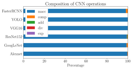
Figure 1.
Percentage of Multiply and ACcumulate (MAC), comparison (comp), addition (add), division (div) and exponent (exp) operations for different networks.
In this work, we propose two implementations of a 5-trit, MAC unit. In addition, a comparative study between the proposed designs, including different temperatures and power supply voltage, is discussed. The remainder of the paper is organized as follows: Section 2 discusses some fundamental definitions of ternary arithmetic and implementation with CNTFET including 1-bit adder and multiplier. Then, Section 3 discusses the implementation of the MAC unit and the necessary building blocks for 5-trits including adder, multiplier, and register. Finally, the simulation results are discussed in Section 4.
2. Ternary Arithmetic and Implementations
2.1. CNTFET-Based Ternary Logic Gates
Recently, CNTFET has been commonly used for designing ternary systems. The exceptional properties of CNTFET such as high thermal conductivity, excellent electric conductivity, mechanical strength, resistance to thermal conditions, stability, and actuation features at low voltages and field emission made CNTFET a technology revolution that motivates researchers to return their interest in ternary system design [24]. A ternary logic function can be characterized as a logic function mapping from to (0,1,2) where x is number on inputs given by (). This function could be an AND, OR, and inverter logic gate. For instance, ternary logic AND and OR can be established as the following Equations (1a) and (1b) respectively. In this work, the three-valued logic levels are an unbalanced representations of logic 0, 1, 2 which correspond to the voltages 0, and i.e., 0 V, 450 mV, 900 mV respectively.
Another widely used function is the inverter logic gate. In ternary logic, there are three different inverters, specifically, Standard Ternary Inverter (STI), Positive Ternary Inverter (PTI) and Negative Ternary Inverter (NTI) [18]. Table 1 shows the definition of ternary logic inverter with input x and output of the inverters are STI, NTI and PTI function of x. STI consists of six transistors while NTI and PTI consist of two transistors. The output decision is taken according to the threshold voltage , which is controlled by the diameter of CNTs. In case of PTI, to obtain mV, it is required to make , which pulls up the middle level (logic ‘1’) to the high level (logic‘2’). In addition, the same works on NTI in reverse in which to obtain in order to pull down the middle level to the ground (logic ‘0’). For STI, the inverter consists of two parts: The first part is the common inverter as in binary responsible for getting the output of inputs logic ‘0’ and ‘2’, while the second part is a diode-connected transistor which is responsible for getting the output of logic ‘1’. The CNT’s dimensions in the first part are always smaller than the dimensions in the second part.

Table 1.
Ternary inverters truth table.
Table 2 shows the truth table for Ternary NOR and NAND, each consists of two parts. The first part is same as the conventional binary NOR and NAND and the second part is the diode connected in which all input cases make the two transistors in the middle ON. In case the inputs pair are (0,0), (0,2), (2,0), (0,1) or (1,0), P-type transistors are ON and N-type transistors are OFF. In this case, the transistors’ impedance of the first part becomes lower than the second part, the output is logic ‘2’, and vice versa for input (2,2). When the inputs are (1,1), (1,2) and (2,2), the transistors in the first part are all OFF while the second part transistors are ON.
Table 2.
Ternary logic gates TNOR and TNAND truth table.
2.2. Single-Trit Multiplier Architecture
Figure 2 shows a single trit-multiplier, implemented in [8]. The implementation is done using a Karnough map (K-map), where the product and carry equations are derived. The K-map only works on binary inputs. Therefore, a ternary decoder is required to convert the ternary inputs to binary outputs as in (2), which would be used later for the K-map as discussed in [8]. Table 3 shows the ternary multiplication product and carry results. The product and carry equations are in (3a) and (3b) respectively.
where and are the outputs from the decoder with input A and B as shown in Figure 2.
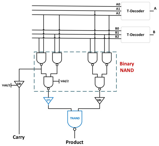
Figure 2.
Single-trit multiplier implementation.
Table 3.
Single-trit Ternary Multiplier Truth Table.
2.3. Single-Trit Full Adder
Figure 3 shows the full adder implementation using the K-map method which is proposed in [6]. Alike the ternary multiplier design which is based on the same implementation based on the K-map, the ternary adder requires a decoder to change the ternary inputs to binary to work on with the K-map method. The truth table for the ternary to binary decoder is depicted in Table 4. Table 5 shows the ternary adder truth table which will contribute to implementing the full adder. The decoder equation is as in Equation (2), while the sum and carry equations are represented in (4a) and (4b), respectively. The AND gates and OR gates between the red sections are binary-based CNTFET technology, while the two-input OR gate in the blue section is a ternary OR based on CNTFET. The binary inverter is used between the stages to avoid the loading effect of the transistors. This design was taken and used to build a 5-trit carry ripple full adder as based in [6] to be used to build the 5-trit multiplier.
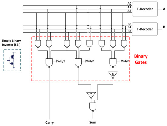
Figure 3.
Single-trit half adder implementation.
Table 4.
Decoder truth table.
Table 5.
Ternary full adder truth table.
3. Ternary Multiply-Accumulate Architecture
In this section, a 5-trit MAC based on CNTFET is discussed which is shown in Figure 4. MAC unit consists of a multiplier, in this case, a 5-trit multiplier, and the result which is calculated is added using the proposed adder to the data that the accumulator stores. This section will show in detail the rest of the components which will be implied to implement the proposed MAC. Moreover, an optimized MAC will be built upon the normal MAC to improve the power and delay analysis.
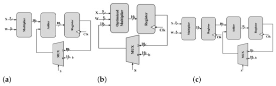
Figure 4.
Proposed 5-trit MAC architectures (a) serial approach, (b) optimized serial and (c) pipelined approach.
3.1. 5-Trit Multiplier
In this work, a 5-trit multiplier is designed while the number of trits is randomly chosen and is equivalent to 8 bits in the binary system. Beginning with the 5-trit multiplier, the method is shown in Figure 5. This figure shows a simple long multiplication process of a 3-trit multiplier. and are the inputs of the multiplication process and 6-trit outputs . For instance, multiplying and would give a product which will be and a carry. The carry of each product will be added to the next product of after shifting the rows as shown in the figure. So, in this case, will be added with the carry of the product and as well . The output of the previous calculation is . Therefore, a 3-trit adder should be placed between the row stages of the first row products and their carries and another will be placed between the result of the first stage and multiplicand of the second stage and so on. This design is called a ripple-carry multiplier based on a carry ripple adder.
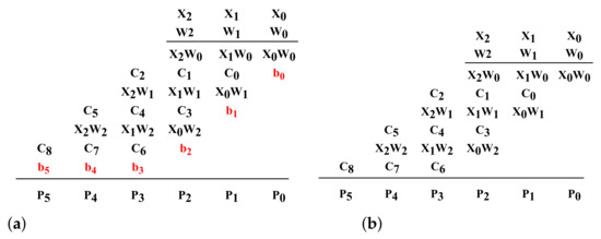
Figure 5.
(a) Multiplication process of design-I. (b) Multiplication Process of design-II.
3.2. 10-Trit Full Adder
In this work, we used a 10-trit full adder in [6] to design the MAC unit. The proposed design is a carry ripple adder based on CNTFET only. We removed the memristors from the design to lower the power as memristors consume a huge amount of power. In the previous work, the comparison showed that the carry-lookahead adder (CLA) showed the best results among the three adders. However in this work, using CNTFET-only-based designs, to implement such a CLA based on CNTFET only will consume a huge area. With a small comparison, the ripple adder was the least area and power due to the decrease in the number of transistors compared to CLA. CLA only showed a better performance in delay only but in designs such as MAC, we need a reliable small power since it is extensively used for DNN accelerators.
The addition process happens after the multiplication process. The ten outputs of the multiplier are added to the desired accumulated data, which is then multiplexed and selected.
3.3. Register
When the final product is calculated and added to the stored results in the accumulator, the main purpose of the register is to save the accumulated result and then pass it again to the adder through a multiplexer to select between the data to be added to the adder. Another purpose for using a register is to avoid data conflict and congestion control in the adder and to give the accumulated data a reasonable time to be calculated and added.
The register can be implemented either based on a ternary dynamic D-flip-flop (DFF) or a ternary static D-flip-flop. In our previous work [5], we showed that the dynamic DFF exhibits better performance compared to the static DFF in terms of latency, power and area.
This register works in two phases. In low Clk: , , and are switched on. The first stage inverts the input and turns D to . The slave is on hold state (high impedance mode) due to , , and being switched off. The output Q remains its previous logic state stored on the output capacitance . In high Clk: , , and are switched on while , , and are off. The roles are reversed, which means the master stage is on hold and the slave acts as an inverter. So, the value stored on propagates to the output node inverted to Q. The overall circuit works as a positive edge-triggered Master–Slave Flip-Flop similar to the basic static DFF proposed in [5].
3.4. MAC Unit
To sum up the whole operation, the 5-trit multiplier is used to get the products and then to be added to the external input b for the first clock cycle. After that, the other input of the multiplexer will be selected for the rest of the operation. MAC operation is discussed carefully in the following equation.
where Y is the accumulated result and b is the external input. and are the data input of the 5-trit multiplier. They are multiplied as depicted before in Figure 5a and added to the external input b. The multiplexer in this operation is a 2 × 1 binary design where it selects b depending on the clock cycle period and then selecting the accumulated result.
3.5. Optimized MAC
The main idea of this optimized design is to find a way to optimize the 10-trit adder shown in Figure 4a and merge it inside the 5-trit multiplier as shown in Figure 4b. The proposed 5-trit multiplier’s method is shown in Figure 5a. Instead of shifting to the left in each stage, leaving a space, the output from the multiplexer is placed in this space. This saves a 4-trit adder and can replace the 10-trit adder with a 6-trit adder. This would improve power, delay and area analysis.
4. Simulation Results and Discussion
As discussed in the introduction, CNTFET shows a better power consumption compared to CMOS and other technologies [5,18]. Therefore, the logic gates such as STI, TNAND and TOR were all simulated extensively and tested using Cadence Virtuoso. In this work, we use a data-calibrated model for 32 nm Virtual source CNTFET (VS-CNTFET) presented in [25,26]. Such model captures the dimensional scaling properties and includes tunneling leakage currents, parasitic resistance and capacitance. CNTFETs suffer some challenges to achieve high performance transistors including parasitic contact resistance and direct source-to-drain tunneling current that could cause high leakage power [27]. In the used model, such non-idealities are included to accurately simulate the existing devices.
The simulations were carried out of different supply voltages (0.8 V, 0.9 V, 1 V), different temperatures (−40 C, 27 C, 85 C) and 0.9 Ghz frequency. Input signals have a fall-and-rise time of 10 ps. The average calculated worst-case delay is taken from the proposed MAC under different scenarios. Then the average power is calculated as well from different scenarios.
The performance analysis of the proposed MAC designs is depicted in Table 6. There are two MAC designs and each has two approaches such as serial or pipeline. The idea of the pipeline approach is to do more calculations in parallel such as addition and multiplication to reduce the delay but power increases slightly. Figure 4c shows the pipelined method applied to the proposed serial MAC. As mentioned before, the optimized MAC will show a better performance due to the four adders component difference from the basic MAC. Thus, it is proven in Table 6 that the optimized MAC gives better results in power and delay than the basic MAC. In the case of area, the optimized proposed MAC shows a better area in terms of the number of transistors than the basic MAC.
Table 6.
Power and delay analysis of the proposed MAC designs for different power supply voltages and temperatures.
5. Conclusions and Future Work
In this paper, we introduced two different designs of MAC. Firstly, the basic MAC was proposed using CNTFET and the ternary number system. Then, an optimized version of the basic MAC to reduce the power, delay, and area. Besides this, two different methods, serial and pipeline, were proposed to implement the MAC unit. The comparative study between the basic and optimized 5-trit MAC units concludes that the pipeline method in any of the designs shows a better performance than the serial method. The optimized MAC also proved to be the best design in the comparison. The optimized design can run up to 300 MHz. The optimized MAC unit can be used in many applications including an efficient hardware accelerator for deep neural networks for efficient deployment at the edge. We will explore the usage of the proposed MAC unit for ternary-valued neural networks in our future work.
Author Contributions
Conceptualization, A.M., M.E.F., I.A. and L.A.S.; Investigation, A.M. and M.E.F.; Methodology, M.E.F.; Project administration, A.G.R.; Supervision, M.E.F., I.A., L.A.S. and A.G.R.; Validation, A.M.; Writing—original draft, A.M.; Writing—review and editing, M.E.F., I.A., L.A.S. and A.G.R. All authors have read and agreed to the published version of the manuscript.
Funding
This research received no external funding.
Conflicts of Interest
The authors declare no conflict of interest.
References
- Chen, K.; Chen, L.; Reviriego, P.; Lombardi, F. Efficient implementations of reduced precision redundancy (RPR) multiply and accumulate (MAC). IEEE Trans. Comput. 2018, 68, 784–790. [Google Scholar] [CrossRef]
- Krishna, A.V.; Deepthi, S.; Devi, M.N. Design of 32—Bit MAC Unit Using Vedic Multiplier and XOR Logic. In Proceedings of International Conference on Recent Trends in Machine Learning, IoT, Smart Cities and Applications; Springer: Berlin/Heidelberg, Germany, 2021; pp. 715–723. [Google Scholar]
- Hayes, B. Third base. Am. Sci. 2001, 89, 490–494. [Google Scholar] [CrossRef]
- Radwan, A.G.; Fouda, M.E. On the Mathematical Modeling of Memristor, Memcapacitor, and Meminductor; Springer: Berlin/Heidelberg, Germany, 2015; Volume 26. [Google Scholar]
- Mohammaden, A.; Fouda, M.; Alouani, I.; Said, L.A.; Radwan, A.G. CNTFET Design of a Multiple-Port Ternary Register File. Microelectron. J. 2021, 2021, 105076. [Google Scholar] [CrossRef]
- Mohammaden, A.; Fouda, M.E.; Said, L.A.; Radwan, A.G. Memristor-CNTFET based Ternary Full Adders. In Proceedings of the 2020 IEEE 63rd International Midwest Symposium on Circuits and Systems (MWSCAS), Springfield, MA, USA, 9–12 August 2020; pp. 562–565. [Google Scholar]
- Soliman, N.S.; Fouda, M.E.; Radwan, A.G. Memristor-CNTFET based ternary logic gates. Microelectron. J. 2018, 72, 74–85. [Google Scholar] [CrossRef]
- Abdelrahman, D.K.; Mohammed, R.; Fouda, M.E.; Said, L.A.; Radwan, A.G. Comparative Study of CNTFET Implementations of 1-trit Multiplier. In Proceedings of the 2020 32nd International Conference on Microelectronics (ICM), Aqaba, Jordan, 14–17 December 2020; pp. 1–4. [Google Scholar]
- Navi, K.; Rad, R.E.S.; Moaiyeri, M.H.; Momeni, A. A low-voltage and energy-efficient full adder cell based on carbon nanotube technology. Nano Micro Lett. 2010, 2, 114–120. [Google Scholar] [CrossRef]
- Raychowdhury, A.; Roy, K. Carbon nanotube electronics: Design of high-performance and low-power digital circuits. IEEE Trans. Circuits Syst. I Regul. Pap. 2007, 54, 2391–2401. [Google Scholar] [CrossRef]
- Schmidt, V.; Riel, H.; Senz, S.; Karg, S.; Riess, W.; Gösele, U. Realization of a silicon nanowire vertical surround-gate field-effect transistor. Small 2006, 2, 85–88. [Google Scholar] [CrossRef] [PubMed]
- Appenzeller, J. Carbon nanotubes for high-performance electronics—Progress and prospect. Proc. IEEE 2008, 96, 201–211. [Google Scholar] [CrossRef]
- Lin, Y.M.; Appenzeller, J.; Knoch, J.; Avouris, P. High-performance carbon nanotube field-effect transistor with tunable polarities. IEEE Trans. Nanotechnol. 2005, 4, 481–489. [Google Scholar] [CrossRef]
- Chang, Y.h.; Butler, J.T. The design of current mode CMOS multiple-valued circuits. In Proceedings of the Twenty-First International Symposium on Multiple-Valued Logic, Victoria, BC, Canada, 26–29 May 1991. [Google Scholar]
- Cho, G.; Lombardi, F. A novel and improved design of a ternary CNTFET-based cell. In Proceedings of the 23rd ACM international conference on Great lakes symposium on VLSI, Paris, France, 2–3 May 2013; pp. 131–136. [Google Scholar]
- Levine, R.; Remacle, F. Realization of complex logic operations at the nanoscale. In Architecture and Design of Molecule Logic Gates and Atom Circuits; Springer: Berlin/Heidelberg, Germany, 2013; pp. 195–220. [Google Scholar]
- Dhande, A.; Ingole, V. Design and implementation of 2 bit ternary ALU slice. In Proceedings of the 3rd International Conference Sciences of Electronic, Technologies of Information and Telecommunications (SETIT), Susa, Tunisia, 17–21 March 2005; pp. 17–21. [Google Scholar]
- Lin, S.; Kim, Y.B.; Lombardi, F. CNTFET-based design of ternary logic gates and arithmetic circuits. IEEE Trans. Nanotechnol. 2009, 10, 217–225. [Google Scholar] [CrossRef]
- Sahoo, S.K.; Akhilesh, G.; Sahoo, R.; Muglikar, M. High-performance ternary adder using CNTFET. IEEE Trans. Nanotechnol. 2017, 16, 368–374. [Google Scholar] [CrossRef]
- Azimi, N.; Hoseini, H.; Shahsavari, A. Designing a novel ternary multiplier using CNTFET. Int. J. Mod. Educ. Comput. Sci. (IJMECS) 2014, 6, 45–51. [Google Scholar] [CrossRef]
- Tung, C.W.; Huang, S.H. A high-performance multiply-accumulate unit by integrating additions and accumulations into partial product reduction process. IEEE Access 2020, 8, 87367–87377. [Google Scholar] [CrossRef]
- Patil, P.A.; Kulkarni, C. A survey on multiply accumulate unit. In Proceedings of the 2018 Fourth International Conference on Computing Communication Control and Automation (ICCUBEA), Pune, India, 16–18 August 2018; pp. 1–5. [Google Scholar]
- Kang, J.; Kim, T. PV-MAC: Multiply-and-accumulate unit structure exploiting precision variability in on-device convolutional neural networks. Integration 2020, 71, 76–85. [Google Scholar] [CrossRef]
- Farhana, S.; Alam, A.H.M.Z.; Khan, S. Spice model design for carbon nanotube field effect transistor (CNTFET). In Proceedings of the 2014 IEEE International Conference on Semiconductor Electronics (ICSE2014), Kuala Lumpur, Malaysia, 27–29 August 2014. [Google Scholar] [CrossRef]
- Lee, C.S.; Wong, H.S.P. Stanford Virtual-Source Carbon Nanotube Field-Effect Transistors Model 1.0.1. 2015. Available online: https://nano.stanford.edu/stanford-cnfet-model; (accessed on 13 September 2021).
- Lee, C.S.; Pop, E.; Franklin, A.D.; Haensch, W.; Wong, H.S. A compact virtual-source model for carbon nanotube FETs in the sub-10-nm regime—Part I: Intrinsic elements. IEEE Trans. Electron Devices 2015, 62, 3061–3069. [Google Scholar] [CrossRef]
- Lee, C.S.; Pop, E.; Franklin, A.D.; Haensch, W.; Wong, H.S.P. A compact virtual-source model for carbon nanotube field-effect transistors in the sub-10-nm regime-part II extrinsic elements, performance assessment, and design optimization. arXiv 2015, arXiv:1503.04398. [Google Scholar]


Publisher’s Note: MDPI stays neutral with regard to jurisdictional claims in published maps and institutional affiliations. |
© 2022 by the authors. Licensee MDPI, Basel, Switzerland. This article is an open access article distributed under the terms and conditions of the Creative Commons Attribution (CC BY) license (https://creativecommons.org/licenses/by/4.0/).