Article

Research on Human Gait Phase Recognition Algorithm Based on Multi-Source Information Fusion

1
Institute of Intelligent Machines, Hefei Institutes of Physical Science, Chinese Academy of Sciences, Hefei 230031, China
2
Department of Science Island, University of Science and Technology of China, Hefei 230026, China
3
School of Artificial Intelligence, Anhui Polytechnic University, Wuhu 241000, China
*
Author to whom correspondence should be addressed.
Electronics 2023, 12(1), 193; https://doi.org/10.3390/electronics12010193
Submission received: 8 December 2022 / Revised: 24 December 2022 / Accepted: 27 December 2022 / Published: 30 December 2022

Abstract

:
Gait phase detection is of great significance in the field of motion analysis and exoskeleton-assisted walking, and can realize the accurate control of exoskeleton robots. Therefore, in order to obtain accurate gait information and ensure good gait phase detection accuracy, a gait recognition framework based on the New Hidden Markov Model (NHMM) is proposed to improve the accuracy of gait phase detection. A multi-sensor gait data acquisition system was developed and used to collect the training data of eight healthy subjects to measure the acceleration and plantar pressure of the human body. Accuracy of the recognition framework, filtering algorithm and window selection, and the missing validation of the generalization performance of the method were evaluated. The experimental results show that the overall accuracy of NHMM is 94.7%, which is better than all other algorithms. The generalization of the performance is 84.3%. The results of this study provide a theoretical basis for the design and control of the exoskeleton.

1. Introduction

In recent years, the study of rehabilitation training for elderly and hemiplegic patients is a very popular field of research. Relevant studies have suggested that during rehabilitation training, the utilization of walking training institutions to assist patients in training can better combine the three elements of weight-bearing, stride and balance, so as to correct abnormal gait in the early stages [1,2]. Related research has shown that the elderly and hemiplegic patients in rehabilitation training who are more involved in the auxiliary movement will experience better rehabilitation effects [3]. Therefore, in this field, walking training institutions need to consider more the sporting ability of the wearer, so as to make up for the lack of users and reduce the intervention of users’ sports tasks. At present, many scholars have studied different auxiliary strategies for different users. In order to obtain a good rehabilitation training effect, walking training institutions must be able to stably follow the action of the human body in real time. Therefore, accurate recognition of human gait is very important for the control system of the walking training mechanism. Shepherd et al. [4] used predefined torque control to define the expected torque of the knee joint as a function of the knee joint angle, and then controlled the current of the motor to allow the knee exoskeleton to track the predefined torque. Strategies based on predefined torques often require the torque table or torque curve to be preadjusted for different wearers. Due to the limited nature of the predefined torque table, it is necessary to introduce some learning methods to increase the system’s adaptability to undefined parts. These learning methods are often more complex and require higher performance of the processor of the control system, and are not suitable for embedded exoskeleton systems. With the development of sensor technology, small, low-cost wearable devices have been widely used in the field of rehabilitation [5].
In the field of human gait recognition, the existing gait recognition work mainly relies on sensor data or image data to identify objects. The gait data used generally include the following: camera image gait data [6], inertial acceleration sensor data [7], micro-electro-mechanical systems (MEMS) [8], pressure-sensor data [9], brain–computer interface (BCI) [10], surface electromyography (SEMG) [11], and passive wireless signals [12] or wave radar data [13]. As described in Vicon [14], the three-dimensional optical motion capture system (OMCS) can obtain high-precision gait data and is used in motion training [15], animation [16], medical analysis [17,18,19,20], and robotics [21]. However, it is only suitable for indoor environments and has a limited range of applications. Ma et al. [22] used electromyography sensors to collect information on the movement of different muscle groups during human activities, which can quickly identify human gait and predict joint torque [23]. However, the sensor device is difficult to wear, and is susceptible to interference from factors such as sweating on the surface of the human body due to direct contact with the skin, which reduces the accuracy of the data. Young et al. [24] proposed a proportional control strategy based on EMG, which generates the control signal of the exoskeleton according to the proportion of EMG signals. Although the results show that it is an effective strategy, its scope of application is limited, and its practicality for wear is weak. Moreover, the EMG signals of some muscles are difficult to measure for elderly and hemiplegic patients, and the strategy based on EMG signals does not apply to them. BCI can directly record human brain activity to make corresponding decisions. It can directly operate the device through willingness in the case of poor human conditions [25], but it cannot detect the unconscious movement of the human brain and is invasive. Therefore, conventional sensor signals (such as IMU and force sensors) may be more suitable for rehabilitation training institutions for elderly and hemiplegic patients.
With the development of artificial intelligence technology, more and more researchers have adopted gait recognition based on deep learning. Gadaleta et al. [26] applied convolutional neural networks (CNN) as feature extractors for gait recognition. The experimental results show that CNN can automatically learn gait features and achieve better recognition performance. Zou et al. [27] used smartphones to collect accelerometer and gyroscope data, proposed a deep neural network that combines CNN and long short-term memory (LSTM), and obtained test results with high recognition rates. Although these methods can achieve better recognition performance, they are not suitable for wearable devices due to the large number of model parameters and large memory usage [28].
At the same time, gait recognition methods based on machine learning, such as support vector machine (SVM) [29], k-nearest neighbor (KNN) [30], and the Hidden Markov Model (HMM) [31], are increasing. Ailisto et al. first presented a sensor-based gait recognition method [32], which collects the acceleration signal corresponding to the waist during walking and uses template matching for gait recognition. Sun et al. [33] proposed an adaptive gait cycle segmentation and matching threshold generation method. Although their method achieves high recognition accuracy, its robustness is poor in complex environments. Mannini et al. [34] applied HMM to identify gait phases using motion information from gyroscopes mounted on the instep. However, the recognition accuracy of this algorithm is not high enough.
For walking training institutions, an easy-to-wear and stable signal transmitter is required for accurate following control. Secondly, a good gait phase recognition accuracy algorithm is needed, and the model memory usage of the algorithm is reduced as much as possible. Finally, under the condition of obtaining good gait phase recognition accuracy, it is necessary to reduce the number of sensors as much as possible to reduce the complexity of device wearability. To achieve this goal, we construct a multimodal human walking recognition (HAR) framework. The framework is equipped with an inertial sensor in three parts of the human body (heel and waist), and a pair of plantar pressure sensors to measure the plantar force of the human body in real time. The walking data of eight healthy subjects were collected. At the same time, this paper adopts a hidden Markov model gait phase recognition algorithm based on modelized state residence time. Usually, the main weakness of the traditional HMM is that it is not accurate enough to model the state duration, and cannot properly characterize the time domain structure of the gait signal. In order to make up for this deficiency, many methods have been proposed to try to add continuous information to traditional HMM. The typical methods are: constructing a state dwell time model based on semi-Markov chain, using the penalty function of state dwell time for post-processing, using time-dependent state transition probability to model state dwell time. However, using the semi-Markov chain to construct the state dwell time model will greatly increase the computational complexity. The penalty function of state dwell time can only affect the recognition path after Viterbi decoding. Therefore, this paper uses time-dependent state transition probability to model state dwell time. Compared with the traditional HMM algorithm, the accuracy of the algorithm is improved by 4.5%. NHMM is used for gait phase detection, and the detection accuracy is compared with other algorithms. The accuracy of gait phase detection of the proposed recognition algorithm is 94.7%, which is better than all other algorithms. The experimental results show that the algorithm can achieve a higher recognition rate.

2. Research Methodology

2.1. Acquisition of Multi-Source Motion Information

The gait information in this paper is composed of pressure sensing information, acceleration sensing information, and gyroscope information. The pressure sensor is placed on the sole of the foot to detect the pressure on the foot. The acceleration sensor and gyroscope are placed on the heel and waist of the human body to detect the movement of the feet and centroid. In order to effectively overcome the problems of low accuracy of plantar pressure acquisition and nonlinear input and output of existing wearable robots, this paper studies and designs a set of motion information acquisition systems, which mainly includes a sensor module, signal conditioning module, wireless Bluetooth transmission module, power module and host computer acquisition software. The working principle of the system is shown in Figure 1.

2.1.1. Plantar Pressure Information Collection Design

When the human body is walking, the change in foot information is periodic, so the required plantar pressure sensor needs to have high repeatability and time lag. At present, the pressure sensor according to its conversion principle can be divided into: piezoelectric, capacitive and resistive pressure sensor. After analysis and comparison, compared with other types of pressure sensors, resistive pressure sensors have advantages such as a wide range, linear output, high sensitivity, small hysteresis error, reliable operation, and good environmental adaptability. MD30-60 is an ultra-thin resistive pressure sensor composed of upper and lower polyester films with light weight, small size and high sensing accuracy. The entire pressure sensitive area is round, with a diameter of about 30 mm, and the diameter of the pressure sensing area is about 25 mm, with a service life of more than 1 million extrusions. It has good time lag and linearity, and fully meets the design requirements of a plantar pressure detection system, as shown in Figure 2a.
The characteristics of human physiological structure determine that the plantar pressure is mainly concentrated in the first to fifth metatarsophalangeal joints and heels [35,36]. In this system, a ZNX-01 pressure insole made of film pressure sensor MD30-60 is used to measure plantar pressure. The pressure insole has five sensors on the forefoot and three sensors on the backfoot. The five sensors on the forefoot are mainly distributed in the thumb area and the first to fifth metatarsophalangeal joints, and the three sensors on the backfoot are distributed in the heel, as shown in Figure 2b.

2.1.2. Inertial Data Sensing Unit

In this paper, MPU9250 is used as inertial data acquisition unit, which integrates a three-axis gyroscope, a three-axis accelerometer, and a three-axis magnetometer, and has good dynamic response characteristics. The maximum measuring range of the accelerometer is ±16 g, and the static measuring accuracy is high. The high-sensitivity Hall sensor is used as a magnetometer for data acquisition. The magnetic induction intensity measurement range is ±4800 μT, which can be used for auxiliary measurement of the yaw angle. By using the Motion Process Library (MPL) provided by InvenSense, the attitude calculation is realized, as shown in Figure 3.

2.1.3. Microcontroller and Wireless Bluetooth Transmission Module

The STM32F103VET6 chip of the microcontroller ARMCortex-M3 core used in this system is simple and lightweight. It has multiple ADC data acquisition channels and can read eight analog signals and perform A/D conversion. At the same time, the microprocessor has SPI and IIC interfaces to support data transmission of MPU9250. In addition, the microprocessor has three UART serial interfaces to support data transmission between the main module and the slave module.
During the measurement, an information acquisition module at the center of the mass acquisition module is fixed on the centroid of the human body to collect motion data. At the same time, a signal acquisition board is fixed at the left and right ankles, respectively. Each board can simultaneously collect eight pressure values and one MPU9250 datum. The left-foot acquisition board is set as a slave. The data are sent to the right foot acquisition board through Bluetooth transmission, and then the data are packaged by the right foot acquisition board and sent to the PC through Bluetooth transmission, as shown in Figure 4.

2.2. Data Preprocessing and Gait Analysis

2.2.1. Preprocessing of Sensor Signals

Before the training of the model parameters, the gait data must be preprocessed. In order to eliminate the noise interference in the original data, from the perspective of eliminating or reducing the systematic error and random error, in this paper, the moving average filtering preprocessing algorithm is used to preprocess the original data. The moving average filtering algorithm has good suppression effect on periodic interference, possesses high smoothness, and is suitable for high frequency oscillation data. The moving average filtering algorithm formula is as follows:
y ( i ) = 1 L j = 0 L 1 y ( i j )
where L is the width of the sliding window, i is the serial number of the data, and y ( i ) is the amplitude value of the original data point i .
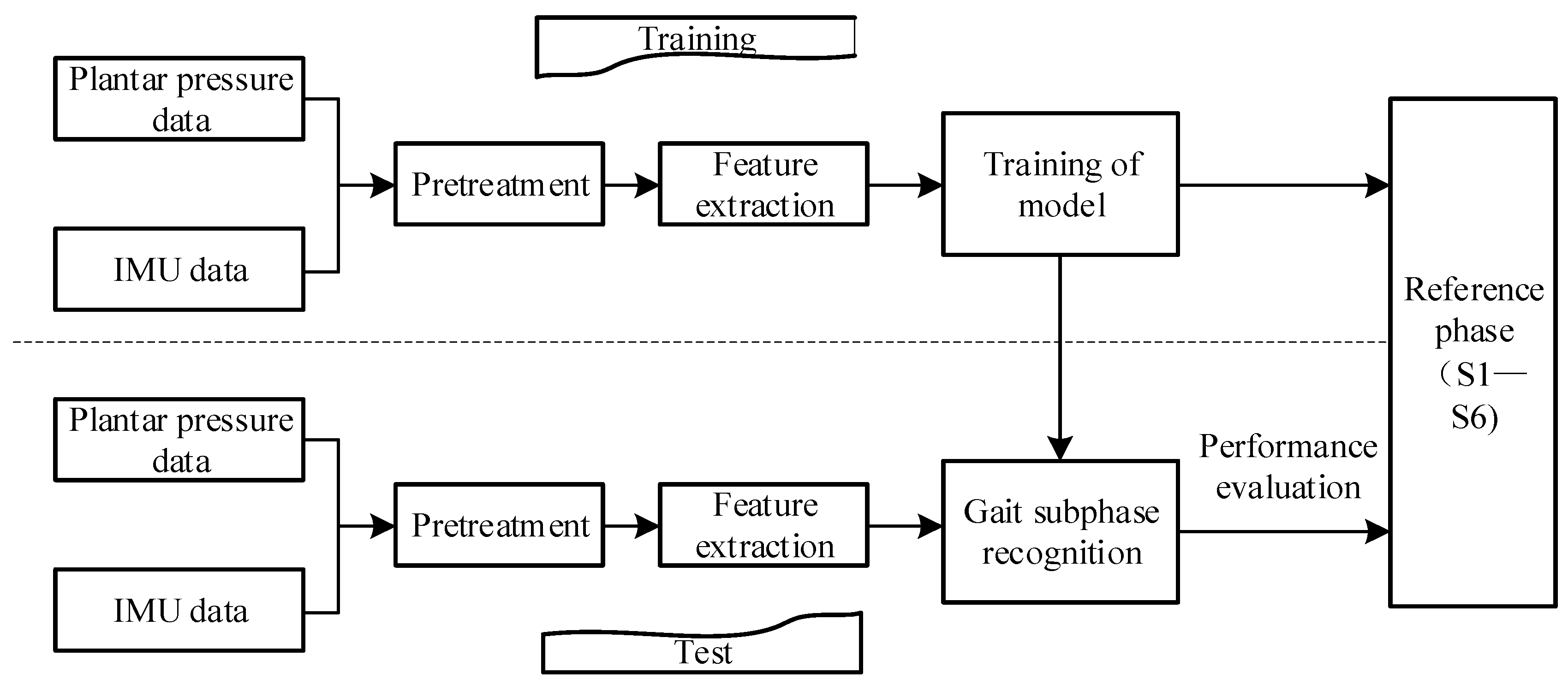
However, in the data moving average filtering, we found that the traditional moving average filtering will have some bad effects on gait data, especially plantar pressure data. As shown in Figure 5a, the filtered data as a whole shift to the left of the timestamp. Therefore, there is a certain time error between the data processed by traditional moving average filtering and the original data. An improved moving average filtering algorithm is proposed to eliminate this error. The algorithm can reduce the time error with the original data while ensuring the original smoothing effect. The filtering effect is shown in Figure 5b. The specific integration process is shown in Figure 6 and Algorithm 1.
Algorithm 1 An Improved Moving Average Filtering Algorithm
Input: Original data X = { x ( 1 ) , x ( 2 ) x ( i ) } , number of repeated filtering n , width of sliding window L serial number of original data sampling points i .
Output: Filtered data X = { x ( 1 ) , x ( 2 ) x ( i ) }
1.  for all X = { x ( 1 ) , x ( 2 ) x ( i ) } do;
2.      Formula (5) is obtained
3.       Y = { y ( i ) } ; n times filtered data;
4.end for
5.Initialization S = { ϕ } , k = { ϕ } ;
6.  Search for all zero data segments in X = { x ( 1 ) , x ( 2 ) x ( i ) } ;
7.while L en [ { x ( i ) } ] 8 ;
8.    Set S { x ( i ) } ;
9.    Set k i ;
10.   for all k do;
11.      { y ( k ) } = 0
12.      X = { y ( i ) }
13.  end for
14.end while

2.2.2. Feature Extraction and Feature Fusion

Figure 7 shows the walking inertial measurement unit (IMU) data of the right heel of a test object. Figure 7a shows the information of three-axis acceleration. It can be seen that the acceleration variation characteristics of the x-axis and z-axis are obvious, while the curve characteristics of the y-axis are not obvious, so auxiliary feature processing can be performed. At the same time, Figure 7b shows the information of the three-axis angular velocity. It can be seen that the angular velocity variation characteristics on the x-axis are more obvious, while the characteristics on the y and z-axis are not obvious. To add some information with obvious characteristics, resultant acceleration and resultant angular velocity are calculated separately:
a m a g = a x 2 + a y 2 + a z 2
where a x , a y , a z respectively represent the information along the x, y, and z axis.
Then, it is connected to the existing three-axis data a x , a y , a z to form ( a x , a y , a z , a m a g ) as the information extraction channel of IMU data.
It is necessary to partition the plantar pressure information before extracting features to reduce the difficulty of data information processing. As shown in Figure 8a, the plantar is divided into four stress areas (toe, forefoot, arch, and heel), and then the data of each stress point in the stress area are summed up and the average value is taken as the stress size of the area.
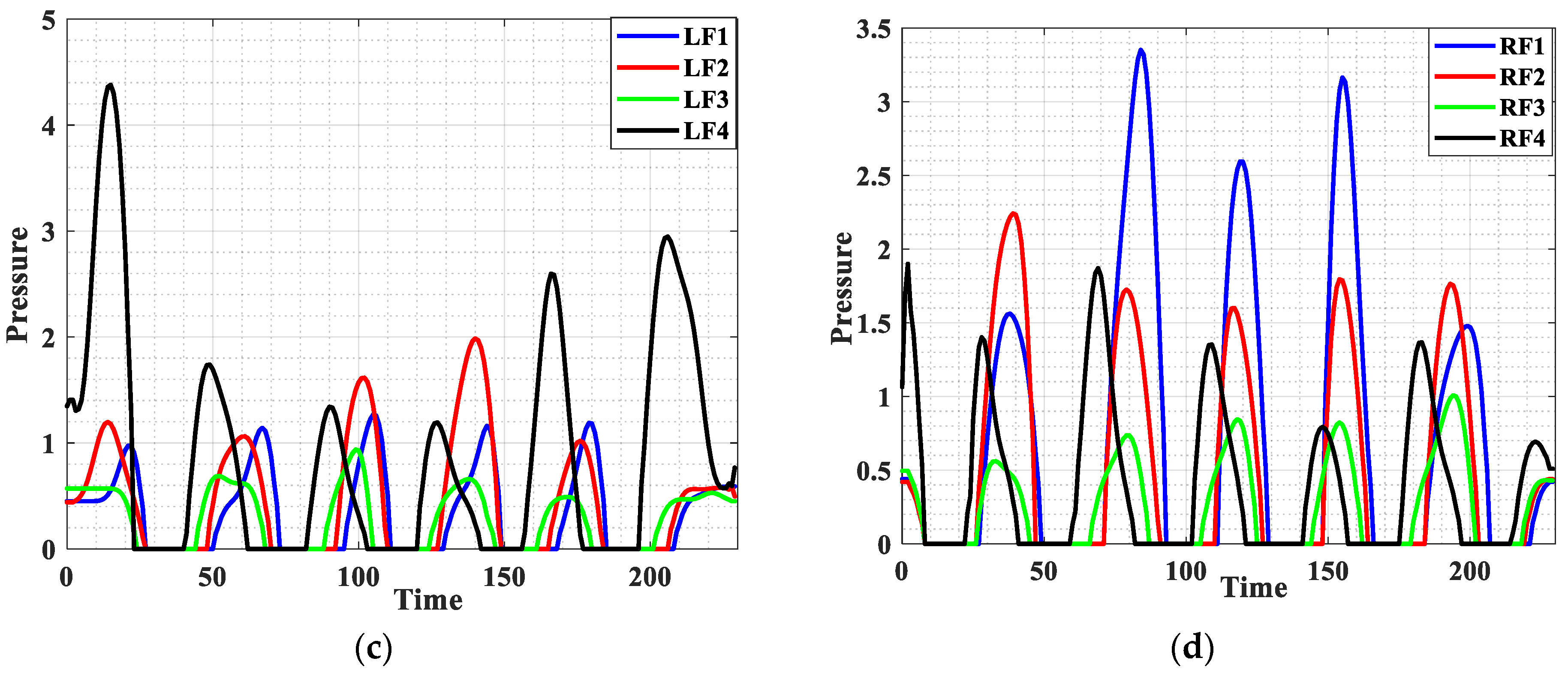
Figure 8b shows a graph of total pressure on the left and right feet during walking. Figure 8c,d show the pressure change curves of the four regions during walking. In the process of the whole touchdown state, the order of the pressure peak in each area of the single foot is heel → arch → forefoot → toe. The results basically maintain the characteristics of the original data.
Therefore, for each pressure insole, we use a total of five pressure signal channels, including four area pressure values and one total pressure value.
The purpose of feature extraction is to obtain the best recognition effect by using the minimum number of features. In this paper, three time domain features [37] are selected. These features are as follows:
μ = 1 N s ( n ) μ = 1 N | s ( n ) s ( n 1 ) | μ Δ = 1 N | s ( n + 1 ) 2 s ( n ) + s ( n 1 ) |
Among them, s ( n ) represents the acquisition signal value, μ represents the average value of the signal s ( n ) , μ is the average value of the absolute value of the first-order differential signal, μ Δ is the absolute value of the average value of the second-order differential signal, and N represents the total number of samples.
In summary, the feature channels extracted in this paper included the acceleration information channel and a combined acceleration information channel in the three-axis direction of each IMU, the three-axis angular velocity information channel, and a combined angular velocity information channel. Therefore, each IMU has eight feature-extraction channels. Each pressure insole has five feature extraction channels, including four area pressure values and one total pressure value. Through Formula (3), three time-domain features are extracted for each information channel: the mean value, the mean value of the absolute value of the first-order differential signal, and the absolute value of the mean value of the second-order differential signal.
After extracting features from IMU and plantar pressure information, the obtained features are fused and organized into a new high-dimensional feature vector. The feature vector has more feature information and can achieve better recognition effect than the feature vector obtained by a single perception mode.
Because the difference in lower limbs will lead to the influence of signal amplitude, in order to eliminate the influence of lower limb information and plantar information dimension on the final result, a normalization process is adopted:
s ^ = ( s s min ) / ( s max s min )
where s ^ represents the normalized value, x represents the value to be normalized, s min is the minimum value of the column where the data are located, and s max is the maximum value of the column where the data are located.

2.2.3. Analysis of Gait Phase

A gait cycle is usually divided into two phases: the standing phase and the swing phase. Generally, according to the needs of the application, it can be divided into 2–7 stages [38]. It can be widely used in intelligent monitoring, rehabilitation medicine, human–computer interaction control, human motion analysis, and other fields. Accurate recognition of human walking gait and associated behavior intention perception is the key to accurate control of an exoskeleton robot control system. During rehabilitation training, semi-active training is usually used for patients with certain autonomous action ability. That is to say, in the process of completing an action, the rehabilitation institution only needs to intervene in one or several stages that require assistance, while other stages only follow the movement. Therefore, in the gait cycle, it is necessary to divide as many sub-phases as possible and accurately identify these stages. The bipedal gait model used in this study divides gait into six phases, as shown in Figure 9.
Each stage of the gait model used in this work determines the state of the two legs. Based on these definitions, the entire dataset is manually segmented by a team member who carefully analyzes the plantar pressure curve and marks short events that divide each cycle into six phases. Figure 10 shows an example of gait segmentation.

3. Gait Recognition Algorithm Based on Hidden Markov

3.1. Description of Hidden Markov Model with Dwell Time

In the traditional HMM model, the probability of the model staying in a certain state for a certain time decreases exponentially with the increase in time. This means that the traditional HMM model cannot properly characterize the time domain structure of the signal, because usually each state should be in the average residence near the highest probability [39]. To resolve the defects of the traditional HMM model, many methods have been proposed to add some additional information to the traditional HMM model. These methods can be roughly divided into three categories: (1) constructing a state dwell time model based on a semi-Markov chain, (2) using the penalty function of state dwell time for post-processing, and (3) using time-dependent state transition probability to model state dwell time. However, using the semi-Markov chain to construct the state dwell time model will greatly increase the computational complexity. Post-processing using the penalty function of state dwell time can only affect the recognition path after Viterbi decoding has taken place [40]. Therefore, this paper models the state dwell time in HMM.
Figure 11 represents the relationship between gait phases, using a left-to-right model without jumps. In this model, only transition to the next stage and self-transition are allowed.
The time evolution of Markov chain is determined by the N dimensional prior probability vector π :
π i = P [ X ( t 0 ) = S i ] ,   1 i N
where π i is the probability when the initial state of the model is i , and satisfies i = 1 N π i = 1 .
Matrix A is the state transition probability matrix:
A = { a i j ( d ) } ,   1 i N 1 i N 1 i N
where a i j ( d ) is the probability of the model moving from state S i to state S j with a dwell time of d t ( i ) = d in state S i up to any time t n .
a i j ( d ) = P [ X ( t n + 1 ) = S j | X ( t n ) = S i , d t ( i ) = d ]
where D is the maximum possible residence time in any state, and a i j ( d ) satisfies j = 1 N a i j ( d ) = 1 .
The observable output can be modeled using discrete or continuous random variables. In this paper, a probability density function weighted by multiple Gaussian distributions is adopted:
b i ( O ) = k = 1 K w k N ( O ; μ k , U k | X ( t n ) = S i )
where O is the observation vector; w k , μ k , and U k are the mixed weight, mean vector, and variance matrix of the k th normal distribution in state S i .

3.2. Model Training

Based on the analysis in Section 2.2.3, the observed signals are modeled by a six-state hidden Markov model (HMM). S = { S 1 , S 2 S 6 } is a collection of hidden states.
To build an HMM model, λ = ( π , A , B ) parameters must be trained. The expectation maximization Baum–Welch (B–W) algorithm is adopted. The algorithm uses recursive thinking, using a maximum likelihood estimation method to make P ( O | λ ) the local maximum and finally obtain the model parameter λ . For parameter revaluation, an additional function γ t ( i , d , k ) needs to be defined based on the traditional HMM:
γ t ( i , d , k ) = P [ X ( t n ) = S i , d ( i ) = d , m i x t u r e k a t t | O 1 O T , λ ]
Then, with the help of the B–W algorithm, the reassessment formula of each parameter of the model is obtained:
π ¯ i = d = 1 D γ 1 ( i , d , k ) ,   1 i N
a ¯ i j ( d ) = t = 1 T 1 α t ( i , d ) a i j ( d ) b j ( O t + 1 ) β t + 1 ( j , 1 ) t = 1 T 1 α t ( i , d ) β t + 1 ( j , 1 ) ,   1 i N 1 j N
w ¯ i k = t = 1 T d = 1 D γ t ( i , d , k ) t = 1 T d = 1 D l = 1 K γ t ( i , d , l ) ,   1 i N
μ ¯ k l = t = 1 T ( d = 1 D γ t ( i , d , k ) ) O t l t = 1 T d = 1 D γ t ( i , d , k ) , ,   1 i N
U ¯ k l = t = 1 T ( d = 1 D γ t ( i , d , k ) ) ( O t l μ i k l ) ( O t l μ i k l ) T t = 1 T d = 1 D γ t ( i , d , k ) , ,   1 i N

3.3. Subphase Recognition Based on HMM Model

In Section 3.2, we trained the gait recognition model and then input the preprocessed test data into the trained gait model to find the maximum probability P ( O | λ ) of the observation sequence O under the model. At the same time, given the observation sequence and model parameters, hidden states in the observation sequence outputs can be decoded. The model training process is shown in Figure 12, and the process of gait recognition is shown in Figure 13.

4. Experiment and Result Analysis

4.1. Experimental Data Collection

In this paper, the experimental device is as follows: (1) IMU placed in the waist, heel (left, right), used to measure the center of mass and feet acceleration, angular velocity, and other data during human walking. (2) The pressure sensor is placed on the sole of the shoe to detect the pressure of the human foot. The experimental dataset consisted of eight healthy subjects with a height range (168–175 mm) and a weight range (42–80 kg). The subjects had no obvious gait abnormalities and avoided strenuous exercise for one week prior to the experiment. When the subject moves, the exoskeleton passively follows the subject. During a collection, the subjects began in the stage of standing on static feet, then moved their right leg and entered the first gait cycle. They then entered the stage of standing on feet after five straight gait cycles and maintained the same static posture as before. Each action is repeated 10 times. Each subject can choose the speed of movement at will, but the order of the movement tasks is required to remain unchanged, and the right leg is the first to move in each experiment. At the beginning and end of each recording, the subjects stood to avoid the absence of movement at the beginning and end of the collection process. The specific parameters of the subjects are shown in Table 1.

4.2. Algorithm Performance Evaluation

To intuitively measure the effect of the new model obtained by training on the gait phase recognition of the experimental gait, this section evaluates the overall performance of the model. This paper evaluates the size of the filter window, the type of sensing information, and different recognition algorithms to verify the superiority of the proposed recognition framework.

4.2.1. Recognition Based on Single-Channel Sensors

The sensing information of the recognition framework in this paper comes from the multi-source fusion of plantar pressure, accelerometer, and gyroscope information. This section demonstrates that the recognition performance of multi-source fusion information is better than that of single-sensor information. Table 2 shows the gait recognition results using plantar pressure, accelerometer, gyroscope information, and multi-source information fusion, respectively. The overall accuracy of multi-source information fusion can reach 94.7%, while the recognition accuracy of plantar pressure, accelerometer, gyroscope information, and single IMU information is 86.6%, 83.9%, 82.4%, and 87.3%, respectively. It is much lower than the gait recognition result after multi-source information fusion. In addition, the accuracy of gait sub-phase recognition after multi-source information fusion is also much higher than that of single-channel sensor information. Therefore, the recognition performance of multi-source information fusion is better than that of single-sensor information.

4.2.2. Window Size Evaluation

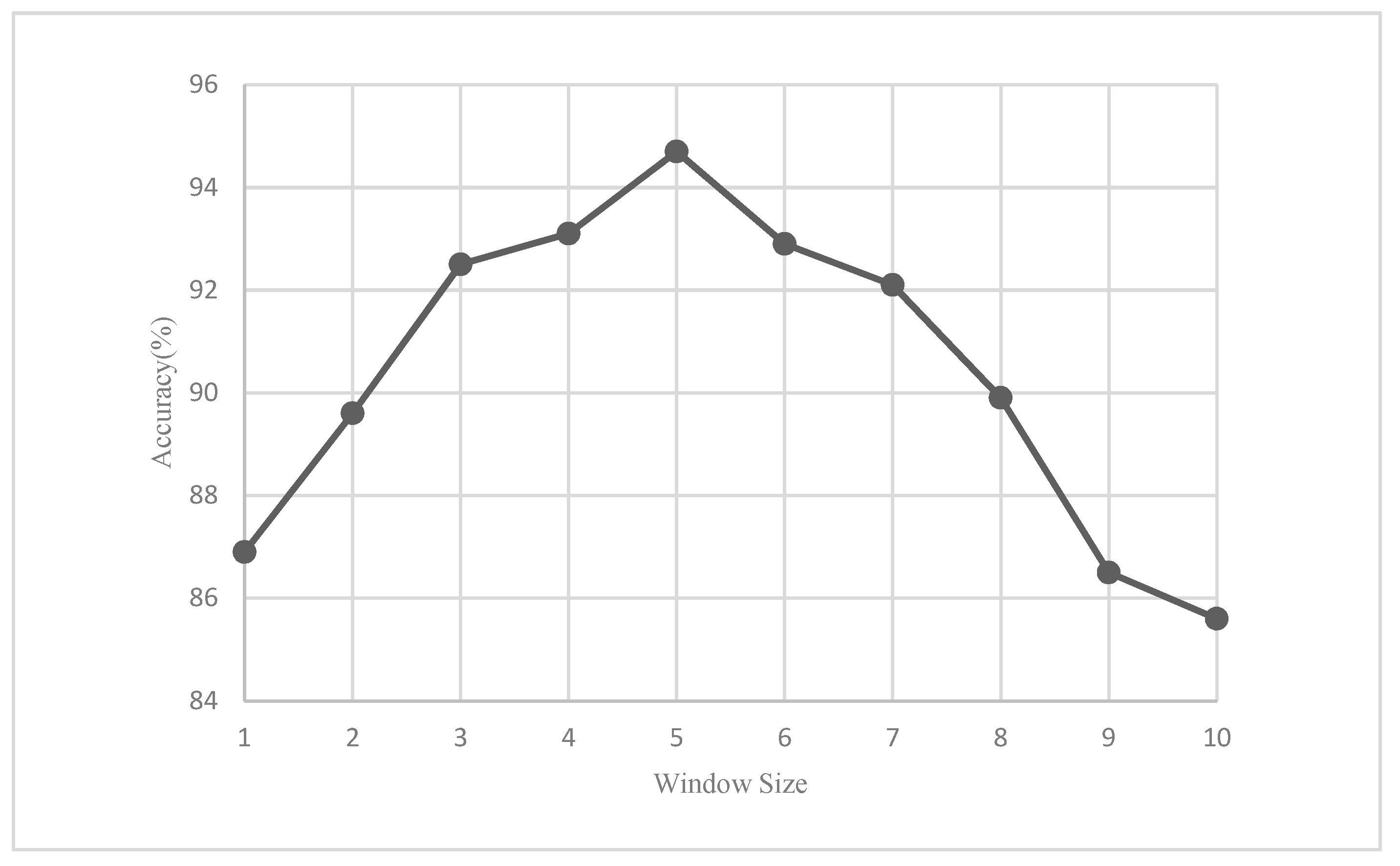
In this section, the impact of different sliding windows on the recognition of the trained model is discussed to determine the final window size. Figure 14 shows the accuracy when the sliding window size of the moving average filtering algorithm is 1–10. With the continuous increase in the sliding window, the accuracy of gait recognition increases and then decreases. Therefore, if the sliding window is too small, the inhibition of data noise is small; on the contrary, if the sliding window is too large, the over-fitting phenomenon of the algorithm will occur, which will lead to a decrease in the algorithm’s performance. The experimental results show that when the sliding window size of the moving average filtering is five, the accuracy of the algorithm is higher than that of other windows, which is more conducive to improving the overall performance of the algorithm.

4.2.3. Gait Recognition Performance Evaluation of Different Classifiers

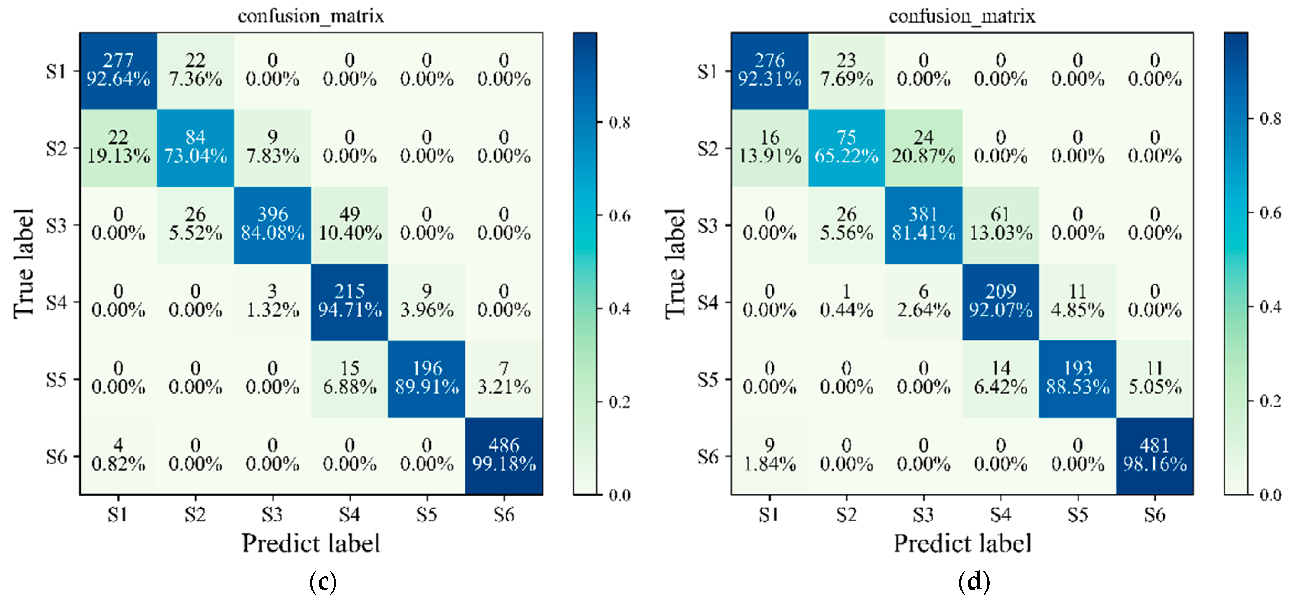
In this section, the recognition performance of NHMM is compared with some common gait detection methods, including SVM, LSTM and traditional HMM. We use the same data and use eight-fold cross validation to obtain the identification results. The results of various algorithms are shown in Table 3, and the confusion matrix is shown in Figure 15. In Table 3, the overall accuracy of NHMM is 94.7%, and the overall accuracy of traditional HMM, LSTM, and SVM is 90.2%, 91.1%, and 88.9%, respectively. Traditional HMM cannot represent the time domain structure of the signal properly. NHMM addresses this by modeling the state dwell time. The results show that the recognition rate has been significantly improved. In the gait cycle S2 and S3 stages, the recognition rate significantly improved from 60.0% and 82.3% to 81.7% and 90.4%, respectively. For LSTM and SVM, the detection result of NHMM is better than the recognition rate of the two, as shown in Figure 15. LSTM usually falls into local optimum during training, while SVM may have over-fitting problems during training. The results show that the recognition performance of NHMM is better than other classifiers. (Reference Code: https://pan.baidu.com/s/1LhNxW_BNENpBJrKJdcrvmg, accessed on 1 January 2022)

4.2.4. Leave-One-Out Validation

To evaluate the generalization performance of the proposed method, the extent to which the trained recognition system is suitable for motion data observed from objects that do not belong to the training set is discussed. Therefore, the missing analysis uses the dataset of seven research objects as the training set, and the dataset of the remaining sub-research object as the test set. The results are shown in Table 4. The second column gives the results of eight-fold cross validation. The third column lists the test results after using the leave-one-out cross-validation method. The results showed that the average accuracy was 93.6% (±0.63) when using eight-fold cross validation for training and testing. In the case of omitting participants, the average accuracy decreased to 84.3% and the standard deviation increased (±3.95). This analysis shows that our method can achieve similar generalization performance when applied to topics that are not included in the training set.

5. Conclusions

In this paper, a gait recognition framework based on NHMM was studied to improve the accuracy of gait phase detection. We developed a multi-source sensor gait data acquisition system to obtain training and testing datasets. Eight healthy subjects were fitted with sensors at the waist and heel and walked on flat ground to obtain data.
Our first evaluation is for the number of sensor information channels, the purpose of which is to show the advantage of the recognition performance of multi-source fusion information over single-sensor information. The second evaluation is for the size of the sliding window, which aims to determine the optimal window size for the recognition rate. The third evaluation is to compare the accuracy of NHMM, traditional HMM, SVM, and LSTM gait phase detection algorithms. Finally, we performed an omission verification to investigate the generalization performance of our method. In summary, the human recognition framework signal source used in this paper is stable and easy to wear. The improved sliding mean filtering algorithm contained in the framework reduces the time error with the original data while ensuring the smoothing effect, and determines the optimal window size through experiments, thereby improving the accuracy of gait phase detection. The NHMM has low memory usage and better recognition accuracy than other algorithms. The gait detection rate is 94.7%. In the case of omitting subjects, the average accuracy rate decreased to 84.3% and the standard deviation increased (±3.95). This shows that our system has good generalization performance. In future research, we can try to use the semi-Markov chain to construct the state time model and use the time-based distribution function to replace the self-transition probability. In the future, we will study motion phase recognition under different conditions, such as stair walking, as well as uphill and downhill walking. At the same time, more detailed preprocessing techniques will be studied, such as the application of feature extraction methods to the original input, the relative normalization of data and frequency transformation techniques.

Author Contributions

Conceptualization, Y.W. and Q.S.; methodology, Y.W.; software, Y.W.; validation, Y.W., Q.S. and T.M.; formal analysis, Y.W. and N.Y.; investigation, Y.W.; resources, B.W.; data curation, Y.W. and B.W.; writing—original draft preparation, Y.W.; writing—review and editing, Q.S. and R.L.; visualization, R.L.; supervision, T.M.; project administration, Q.S; funding acquisition, Q.S. All authors have read and agreed to the published version of the manuscript.

Funding

This research was funded by Supported by the HFIPS Director’s Fund, Grant [No.YZJJ2022QN33, NO.YZJJ2023QN39], Anhui Provincial Key Research and Development Project [No.202004a05020013], Supported by Students Innovation and Entrepreneurship Foundation of USTC [XY2022G04CY].

Informed Consent Statement

Informed consent was obtained from all subjects involved in the study.

Data Availability Statement

The data used to support the findings of this study are included within the article.

Acknowledgments

This work was partly carried out at the Robotic Sensors and Human–Computer Interaction Laboratory, Hefei Institute of Intelligent Machinery, Chinese Academy of Sciences.

Conflicts of Interest

The authors declare no conflict of interest.

References

  1. Wang, Y.Y.; Ma, Y. Development and application of a new walking training device for lower limb rehabilitation. Med. J. Natl. Defending Forces Northwest China 2021, 42, 654–658. [Google Scholar]
  2. Gao, Q. The effect of early hyperbaric oxygen combined with lower limb rehabilitation robot training on walking ability of patients with cerebral apoplexy hemiplegia. Pract. J. Clin. Med. 2018, 15, 98–100. [Google Scholar]
  3. Warraich, Z.; Kleim, J.A. Neural plasticity: The biological substrate for neurorehabilitation. PM & R 2010, 2, S208–S219. [Google Scholar]
  4. Shepherd, M.K.; Rouse, E.J. Design and validation of a torque-controllable knee exoskeleton for sit-to-stand assistance. IEEE/ASME Trans. Mechatron. 2017, 22, 1695–1704. [Google Scholar] [CrossRef]
  5. Zhou, J.; Cao, Z.F.; Dong, X.L.; Lin, X.D. Security and privacy in cloud-assisted wireless wearable communications: Challenges, solutions and, future directions. IEEE Wireless Commun. 2015, 22, 136–144. [Google Scholar] [CrossRef]
  6. Wang, Y.; Du, B.; Shen, Y.; Wu, K.; Zhao, G.; Sun, J.; Wen, H. EV-gait: Event-based robust gait recognition using dynamic vision sensors. In Proceedings of the IEEE/CVF Conference on Computer Vision and Pattern Recognition 2019, Long Beach, CA, USA, 15–20 June 2019; pp. 6358–6367. [Google Scholar]
  7. Chen, C. UTD-MHAD: A multimodal dataset for human action recognition utilizing a depth camera and a wearable inertial sensor. In Proceedings of the IEEE International Conference on Image Processing, Quebec City, QC, Canada, 27–30 September 2015. [Google Scholar]
  8. Liu, N.; Su, Z.; Li, Q.; Zhao, H.; Qi, W. A Combined CKF-PSR Method For Random Noise Compensation of Vibratory Gyroscopes. J. Ind. Inf. Integr. 2021, 25, 100241. [Google Scholar] [CrossRef]
  9. Jia, X.H.; Wang, T.; Liu, J.Y.; Li, T.J. Gait recognition and intention perception method based on human body model mapping. Chin. J. Sci. Instrum. 2020, 41, 236–244. [Google Scholar]
  10. Diya, S.Z.; Prorna, R.A.; Rahman, I.I.; Islam, A.B.; Islam, M.N. Applying Brain-Computer Interface technology for Evaluation of user experience in playing games. In Proceedings of the International Conference on Electrical, Computer and Communication Engineering (ECCE 2019), Cox’s Bazar, Bangladesh, 7–9 February 2019; pp. 16–19. [Google Scholar]
  11. Xi, X.; Jiang, W.; Lü, Z.; Miran, S.M.; Luo, Z.Z. Daily activity monitoring and fall detection based on surfaceelectromyography and plantar pressure. Complexity 2020, 2020, 9532067. [Google Scholar] [CrossRef]
  12. Wei, W.; Liu, A.; Shahzad, M. Gait recognition using wifi signals. In Proceedings of the 2016 ACM International Joint Conference ACM, San Francisco, CA, USA, 13–17 August 2016; pp. 363–373. [Google Scholar]
  13. Jiang, X.; Zhang, Y.; Yang, Q.; Deng, B.; Wang, H. Millimeter-Wave Array Radar-Based Human Gait Recognition Using Multi-Channel Three-Dimensional Convolutional Neural Network. Sensors 2020, 20, 5466. [Google Scholar] [CrossRef] [PubMed]
  14. Sutherland, D.H. The evolution of clinical gait analysis part III–kinetics and energy assessment. Gait Posture 2005, 21, 447–461. [Google Scholar] [CrossRef]
  15. Van der Kruk, E.; Reijne, M.M. Accuracy of human motion capture systems for sport applications; state-of-the-art review. Eur. J. Sport Sci. 2018, 18, 806–819. [Google Scholar]
  16. Daniel, H. Robust solving of optical motion capture data by denoising. ACM Trans. Graph. 2018, 37, 165. [Google Scholar]
  17. Ali, A.; Sundaraj, K.; Ahmad, B.; Ahamed, N.; Islam, A. Gait disorder rehabilitation using vision and non-vision based sensors: A systematic review. Bosn. J. Basic Med. Sci. 2012, 12, 193–202. [Google Scholar] [CrossRef] [PubMed] [Green Version]
  18. Glowinski, S.; Blazejewski, A.; Krzyzynski, T. Inertial Sensors and Wavelets Analysis as a Tool for Pathological Gait Identification. In Innovations in Biomedical Engineering; Springer: Cham, Switzerland, 2017. [Google Scholar]
  19. Shubao, Y.; Chen, C.; Hangyu, Z.; Xinping, W.; Wei, C. Neural Networks for Pathological Gait Classification Using Wearable Motion Sensors. In Proceedings of the Biomedical Circuits and Systems Conference, Nara, Japan, 17–19 October 2019. [Google Scholar]
  20. Arellano-González, J.C.; Medellín-Castillo, H.I.; Cervantes-Sánchez, J.J. Identification and Analysis of the Biomechanical Parameters Used for the Assessment of Normal and Pathological Gait: A Literature Review. In Proceedings of the ASME 2019 International Mechanical Engineering Congress and Exposition, Salt Lake City, UT, USA, 11–14 November 2019. [Google Scholar]
  21. Zhang, J.; Li, P.; Zhu, T.; Zhang, W.; Liu, S. Human motion capture based on kinect and IMUs and its application to human-robot collaboration. In Proceedings of the 2020 5th International Conference on Advanced Robotics and Mechatronics (ICARM), Shenzhen, China, 18–21 December 2020; pp. 392–397. [Google Scholar]
  22. Ma, W.; Zhang, X.; Yin, G. Design on intelligent perception system for lower limb rehabilitation exoskeleton robot. In Proceedings of the International Conference on Ubiquitous Robots and Ambient Intelligence, Xi’an, China, 19–22 August 2016; pp. 587–592. [Google Scholar]
  23. Wang, C.; Wu, X.; Wang, Z.; Ma, Y. Implementation of a brain-computer interface on a lower-limb exoskeleton. IEEE Access 2018, 6, 38524–38534. [Google Scholar] [CrossRef]
  24. Young, A.J.; Gannon, H.; Ferris, D.P. A biomechanical comparison of proportional electromyography control to biological torque control using a powered hip exoskeleton. Front. Bioeng. Biotechnol. 2017, 5, 37. [Google Scholar] [CrossRef] [PubMed] [Green Version]
  25. He, Y.; Eguren, D.; Azorín, J.M.; Grossman, R.G.; Luu, T.P.; Contreras-Vidal, J.L. Brain-machine interfaces for controlling lower-limb powered robotic systems. J. Neural Eng. 2018, 15, 021004. [Google Scholar] [CrossRef]
  26. Gadaleta, M.; Rossi, M. IDNet: Smartphone-based gait recognition with convolutional neural networks. Pattern Recognit. 2018, 74, 25–37. [Google Scholar] [CrossRef] [Green Version]
  27. Zou, Q.; Wang, Y.; Wang, Q.; Zhao, Y.; Li, Q. Deep learning-based gait recognition using smartphones in the wild. IEEE Trans. Inf. Forensics Secur. 2020, 15, 3197–3212. [Google Scholar] [CrossRef] [Green Version]
  28. Huang, H.; Zhou, P.; Li, Y.; Sun, F. A lightweight attention-based CNN model for efficient gait recognition with wearable IMU sensors. Sensors 2021, 21, 2866. [Google Scholar] [CrossRef]
  29. Ahmad, M.; Raza, R.A.; Mazzara, M. Multi sensor-based implicit user identification. Comput. Mater. Contin. 2021, 68, 1673–1692. [Google Scholar] [CrossRef]
  30. Choi, S.; Youn, I.H.; Lemay, R. Biometric gait recognition based on wireless acceleration sensor using k-nearest neighbor classification. In Proceedings of the International Conference on Computing, Beijing, China, 22–23 May 2014. [Google Scholar]
  31. De Rossi, S.M.; Crea, S.; Donati, M.; Reberšek, P.; Novak, D.; Vitiello, N.; Lenzi, T.; Podobnik, J.; Munih, M.; Carrozza, M.C. Gait segmentation using bipedal foot pressure patterns. In Proceedings of the IEEE Ras & Embs International Conference on Biomedical Robotics & Biomechatronics, Rome, Italy, 24–27 June 2012. [Google Scholar]
  32. Ailisto, H.J.; Lindholm, M.; Mantyjarvi, J.; Vildjiounaite, E.; Makela, S.M. Identifying people from gait pattern with accelerometers. Proc. SPIE Int. Soc. Opt. Eng. 2005, 5779, 7–14. [Google Scholar]
  33. Sun, F.M.; Mao, C.F.; Fan, X.M.; Li, Y. Accelerometer-based speed-adaptive gait authentication method for wearable IoT devices. IEEE Int. Things. J. 2018, 6, 820–830. [Google Scholar] [CrossRef]
  34. Mannini, A.; Sabatini, A.M. Machine learning methods for classifying human physical activity from on-body accelerometers. Sensors 2010, 10, 1154–1175. [Google Scholar] [CrossRef] [PubMed] [Green Version]
  35. Zhang, Y.; Awrejcewicz, J.; Szymanowska, O.; Shen, S.; Zhao, X.; Baker, J.S.; Gu, Y. Effects of severe hallux valgus on metatarsal stress and the metatarsophalangeal loading during balanced standing: A finite element analysis. Comput. Biol. Med. 2018, 97, 1–7. [Google Scholar] [CrossRef] [Green Version]
  36. Vigneshwaran, S.; Murali, G. Foot plantar pressure measurement system for static and dynamic condition. IOP Conf. Ser. Mater. Sci. Eng. 2020, 993, 012106. [Google Scholar] [CrossRef]
  37. Ehatisham-Ul-Haq, M.; Javed, A.; Azam, M.A.; Malik, H.M.; Irtaza, A.; Lee, I.H.; Mahmood, M.T. Robust human activity recognition using multimodal feature-level fusion. IEEE Access 2019, 7, 60736–60751. [Google Scholar] [CrossRef]
  38. Zhang, X.G.; Tang, H.; Fu, C.J.; Shi, Y.L. Gait Recognition algorithm based on hidden markov model. Comput. Sci. 2016, 43, 285–289, 302. [Google Scholar]
  39. Du, S.P. Improved forward-back algorithm for hidden model with dwell time. Pure Appl. Math. 2008, 24, 580–584. [Google Scholar]
  40. Guo, Q.; Chai, H.X. Modeling state dwell time in hidden markov model. J. Tsinghua Univ. (Sci. Technol.) 1999, 39, 98–101. [Google Scholar]
Figure 1. Information collection system (MPU9250 is used as IMU, MD30-60 is used as plantar pressure sensor and STM32F103VET6 is used as MCU).
Electronics 12 00193 g001
Figure 2. Film pressure sensor and insole configuration. (a) Thin-film pressure sensor MD30-60; (b) insole sensor configuration (the number 1-8 is the sensor arrangement number).
Electronics 12 00193 g002
Figure 3. Motion Information Collection Module. (a) Waist information acquisition module; (b) heel and foot information acquisition module.
Electronics 12 00193 g003
Figure 4. Sensor information acquisition configuration.
Electronics 12 00193 g004
Figure 5. Comparison of filtering effect of AD8 channel of plantar pressure sensor. (a) Traditional moving average filtering; (b) improved sliding mean filtering.
Electronics 12 00193 g005
Figure 6. Improved Moving Average Filtering Algorithm flow chart.
Electronics 12 00193 g006
Figure 7. Right foot IMU walking data. (a) Acceleration information; (b) angular velocity information.
Electronics 12 00193 g007
Figure 8. Division of plantar pressure and walking data. (a) Division of plantar pressure; (b) total pressure value of both feet; (c) left foot pressure value; (d) right foot pressure value.
Electronics 12 00193 g008aElectronics 12 00193 g008b
Figure 9. Phase division of walking cycle. RHS (Right heel strike): At this stage, the left foot pressure decreases, the right foot pressure increases, and the support center of gravity begins to shift to the right foot. RFF (Right foot flat): At this stage, the support center of gravity is completely transferred to the right foot, and the left foot enters the swing period. RFS (Right foot support): At this stage, the left foot ends the swing period and begins to touch the ground. LHS (Left heel strike): This stage is the bipedal support stage before the right foot swings. The right foot pressure decreases, the left foot pressure increases, and the support center of gravity begins to shift to the left foot. LFF (Left foot flat): At this stage, the support center of gravity is completely transferred to the left foot, and the right foot enters the swing period. LFS (Left foot support): At this stage, the right foot ends the swing phase and is ready to touch down.
Electronics 12 00193 g009
Figure 10. Gait phase egmentation based on plantar pressure(the red line in the figure represents the duration of each stage, and the vertical color line is the dividing line of each stage).
Electronics 12 00193 g010
Figure 11. HMM model topology diagram.
Electronics 12 00193 g011
Figure 12. Flow chart of model training.
Electronics 12 00193 g012
Figure 13. Design block diagram of gait recognition algorithm.
Electronics 12 00193 g013
Figure 14. Comparison of recognition rate under different sliding windows.
Electronics 12 00193 g014
Figure 15. Confusion matrices for the (a) NHMM, (b) HMM, (c) LSTM, and (d) SVM models.
Electronics 12 00193 g015aElectronics 12 00193 g015b
Table 1. Subject Parameters.
SubjectAge
(y)
Height
(kg)
Weight
(cm)
Shoe Size
(EU)
1267117342
2286816941.5
3245617241.5
4268017542
5316617241.5
6306817442
7295217241.5
8254616840
Table 2. Eight-fold cross validation recognition effect of each channel’s sensing information (S1–S6 correspond to RHS, RFF, RFS, LHS, LFF, and LFS, respectively).
Sensor(s)S1 (%)S2 (%)S3 (%)S4 (%)S5 (%)S6 (%)Aggregated (%)
Acc87.951.377.886.385.893.183.9
Gyro83.953.975.691.280.791.482.4
Force90.350.480.392.588.195.786.6
Acc + Gyro89.654.878.993.389.497.687.3
Acc + Gyro + Force96.381.790.497.494.999.894.7
Table 3. 8-fold cross validation recognition results of four classifiers (S1–S6 correspond to RHS, RFF, RFS, LHS, LFF, and LFS, respectively).
MethodS1 (%)S2 (%)S3 (%)S4 (%)S5 (%)S6 (%)Aggregated (%)
NHMM96.381.790.497.494.999.894.7
HMM94.960.082.393.891.799.690.2
LSTM92.673.184.194.789.999.191.1
SVM92.365.281.492.188.598.188.9
Table 4. Result of leave-one-out validation.
Test SubjectCross-Validation Accuracy (%)Left Out Subject Accuracy (%)
193.486.8
293.984.2
394.785.9
492.982.1
593.180.4
694.784.6
792.385.9
893.484.6
Average93.684.3
Standard deviation0.633.95
Disclaimer/Publisher’s Note: The statements, opinions and data contained in all publications are solely those of the individual author(s) and contributor(s) and not of MDPI and/or the editor(s). MDPI and/or the editor(s) disclaim responsibility for any injury to people or property resulting from any ideas, methods, instructions or products referred to in the content.