Article

A THz Slot Antenna Design Using Analytical Techniques

Department of Electrical & Electronic Engineering, Ariel University, Ariel 40700, Israel
*
Author to whom correspondence should be addressed.
Electronics 2023, 12(10), 2233; https://doi.org/10.3390/electronics12102233
Submission received: 9 March 2023 / Revised: 1 May 2023 / Accepted: 10 May 2023 / Published: 14 May 2023

Abstract

:
Slot antennas are very popular microwave antennas, and slotted waveguides are used for high frequency radar systems. A thin slot in an infinite ground plane is the complement to a dipole in free space. This was described by H.G. Booker, who extended Babinet’s principle from optics to show that the slot will have the same radiation pattern as a dipole such that the E and H fields are swapped. As a result, the polarization is rotated, so that radiation from the vertical slot is polarized horizontally. In this work, we show how this straightforward analytical technique can be used for the design of high-frequency THz slot antennas. The analysis is then corroborated by using a numerical simulation which validates the performance parameters predicted by the analytical technique. We show by simulation that, despite the simplicity of our classical approach, we obtained useful results, even at THz frequencies. We show that gradually moving the slot position from the centerline improves the antenna’s performance.

1. Introduction

Slot antennas are very popular microwave antennas, and slotted waveguides are used for high frequency radar systems [1,2,3,4,5,6,7,8,9,10,11,12,13,14,15,16]. A thin slot in an infinite ground plane is the complement to a dipole in free space. This was described by H.G. Booker [2], who extended Babinet’s principle from optics to show that the slot will have the same radiation pattern as a dipole such that the E and H fields are swapped. As a result, the polarization is rotated, so that radiation from the vertical slot is polarized horizontally. For instance, a vertical slot has the same pattern as a horizontal dipole with the same dimensions, and we are able to calculate the radiation pattern of a dipole. Thus, a longitudinal slot in the broad wall of a waveguide radiates just like a dipole perpendicular to the slot. By using this principle, it is easier to analyze slot antennas using the theory of dipole antennas. The slots are typically thin and 0.5 wavelengths long. The position of the slots affects the intensity of the transmitted power by directly causing the impedance matching of the antenna; good impedance matching produces the maximum efficiency of power transmission. In [15], a waveguide-fed transverse slot was analyzed using the Method of Moments (MoM) formulation, wherein the internal admittance matrix elements were evaluated from image theory and using the images of the slot from waveguide walls. The contribution from all the images not in the same row as the slot was evaluated using a closed-form expression and a rapidly converging series with negligible contribution. The contribution from the row containing the reference slot was evaluated by adding the mutual admittance between a few images and the reference slot using some recently developed simple and accurate approximations. The formulation was extended to transverse slots radiating between the baffles. The results calculated using this simple, efficient, and intuitive method were in excellent agreement with other theoretical as well as measured results. The technique can be extended to other slot configurations, such as an inclined slot, and for other slot aperture distributions in configurations permitting image formation, such as with an edge condition. Despite the fact that we do not consider images, our results are satisfactory in that the simulation results show that the antenna gain is 18.4 dBi and the azimuth beam width is 1.7 , compared to 21.8 dBi and 0.7 in the analytical design. It may be that adding images may reduce the discrepancy further; however, this is beyond the scope of the current work.
In [14], a straightforward design procedure for a slotted antenna fed by a single-ridge waveguide is introduced. The proposed method does not use the analytical method to derive the general relation between the backward- and forward-scattering dominant mode coefficients and slot voltage, as is done in the current paper. Rather, in [14], the general relation connecting the backward- and forward-scattering dominant mode coefficients to the slot electric field distribution is derived using an available electromagnetic field simulator and by fitting some proper polynomials to the derived data. Then, the well-known Elliott’s design procedure for arrays of longitudinal slots in the broad wall of an air-filled rectangular waveguide is developed for the slot array feed by a single-ridge waveguide. A four-by-five array is designed and simulated which verifies the design specifications and the proposed design procedure. Compared with that approach, our approach is simpler, more analytical, and straightforward.
In this paper, an antenna based on a slotted waveguide is analyzed analytically and designed for the THz band (frequencies of about 330 GHz).
Such antennas may be useful for multiple applications. Medical applications include tooth imaging, cancer treatment and detection, fungus treatment [17,18,19,20,21,22,23,24,25], and surgery.
The existence of unique spectral lines in the THz band allows for the characterization and analysis of materials. Thus, a THz antenna can be useful to monitor the composition of the atmosphere, including gases and particles which cause air pollution.
Electromagnetic energy transfer to drones and balloons using THz radiation may elongate the duration of their mission without the need to land for refueling. For this application, the shorter wavelength of THz is an advantage as this allows a higher gain for a smaller antenna.
There are also security applications of the suggested THz antenna in places such as airports to discover concealed weapons or illegal drugs. In this case, passengers are irradiated by the non-ionizing and harmless THz radiation, and the reflected radiation is used to create an image which delineates the hidden object. Furthermore, spectroscopical analysis of the THz radiation reveals the nature of the hidden object, determining if it is a harmless candy or a dangerous illegal drug.
Communication applications may include point-to-point or point-to-multipoint and “last mile” connections.
The structure of the paper is as follows: Section 2 will be devoted to the THz spectral range and its applications. In Section 3, the antenna design is presented, and the waveguide dimensions and the operation frequency are briefly discussed. First, we describe a single slot on a rectangular waveguide and show that it can be described using a model of a transmission line. By using this model, equations that relate the slot position to the transmitted power are developed. This model was expanded for an array of slots on a rectangular waveguide in order to design the slot antenna. We show that gradually moving the slot position from the centerline improves the antenna’s performance. In Section 4, an antenna based on a slotted rectangular waveguide in the THz band was designed and simulated. The conclusions are given in Section 5.

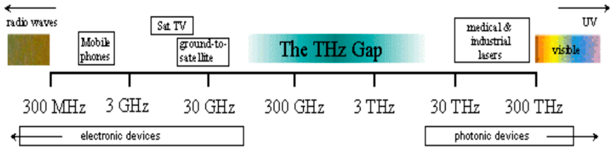
2. The Importance of the THz Frequency Band

Terahertz radiation occupies a large portion of the electromagnetic spectrum between infrared and millimeter waves. The common definition of the terahertz range is the spectral range of 100 GHz −10 THz (see Figure 1). This corresponds to wavelengths from 30 µm to 3 mm or approximately 3 cm−1 to 300 cm−1 on the wave number scale.
The THz range is important as it allows the identification of molecules based on their total structure, thus making chemical identification of closely resembling molecules possible. Moreover, THz radiation is ‘soft’ and non-ionizing. The high intensity of the thermal background radiation and a lack of robust sources and sensitive detectors restricted for many years both exploration and applications in the THz range. For a long time, the submillimeter radiation could only be obtained from weak blackbody radiators and a few gas lasers which could only be produced in laboratory environments. This situation changed around 1990, when advances in the coherent generation and detection of short pulses of THz radiation initiated an intensive development of basic and applied studies. At present, extensive interest and activity exists in fundamental as well as application-oriented research in the THz spectral region [26,27,28]. Thousands of publications directly addressing the subject have been published in the previous decades in scientific periodicals.

2.1. THz Radiation and Safety Issues

Over the past years, there has been significant interest in employing terahertz (THz) technology, spectroscopy, and imaging for security applications. There are three prime motivations for this interest:
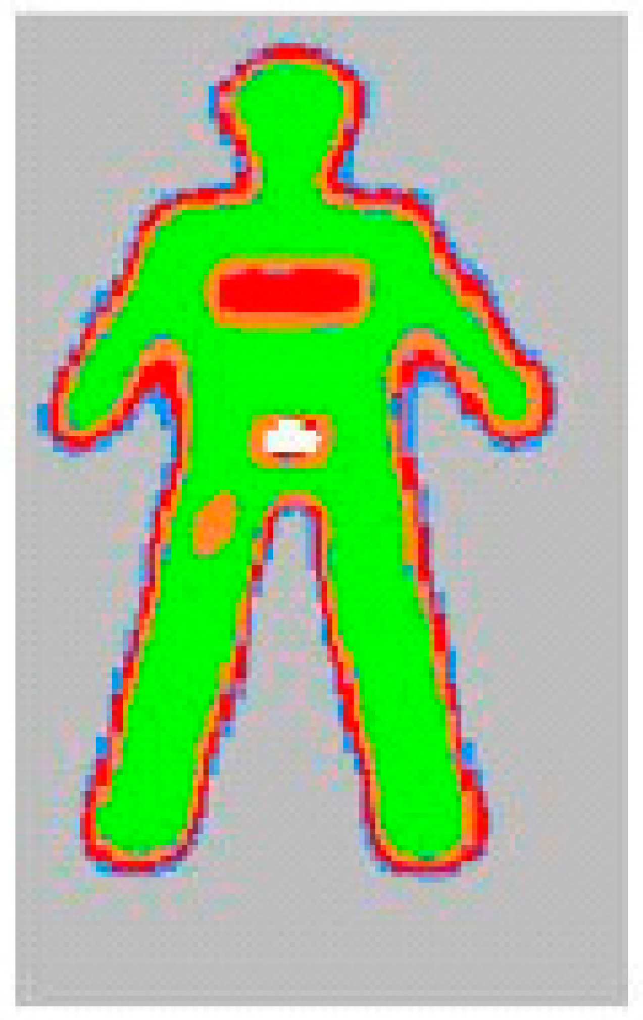
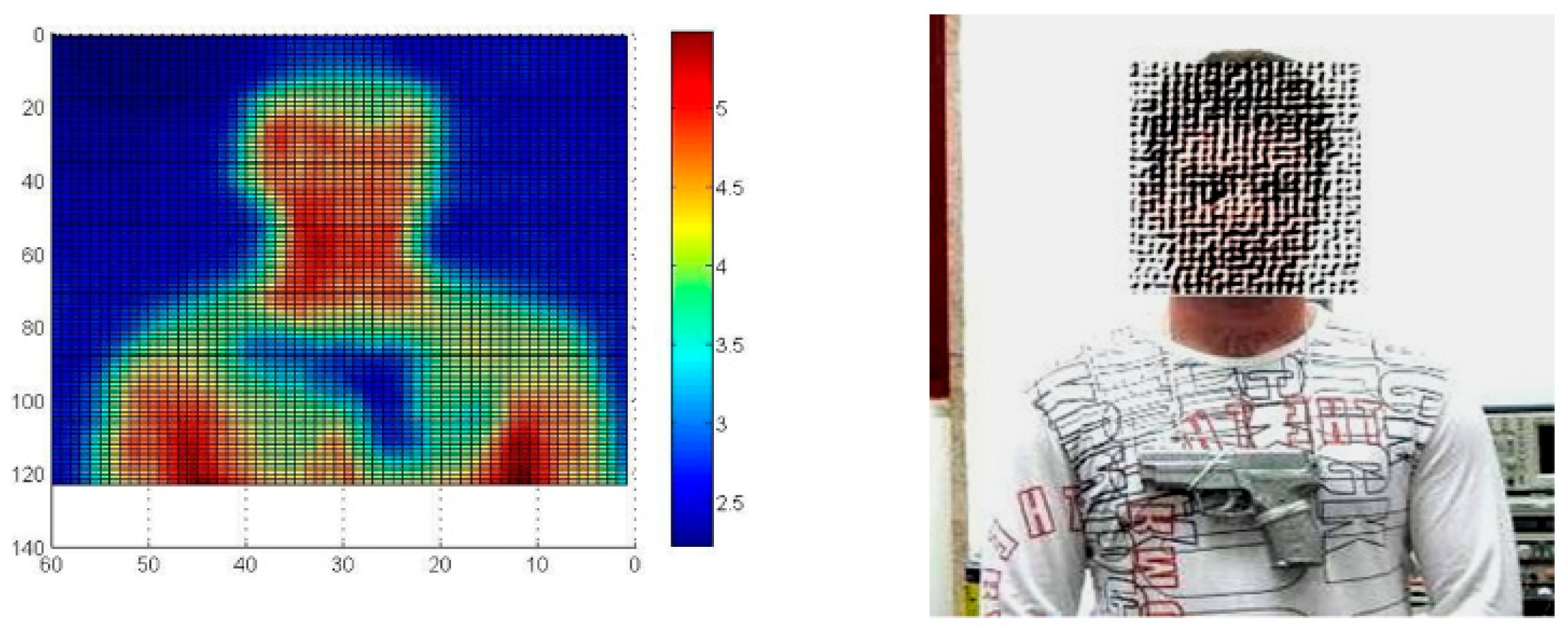
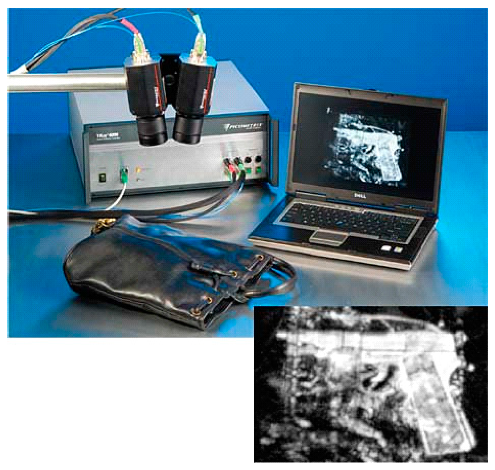
  • THz radiation can detect concealed weapons since many non-metallic, non-polar materials such as clothing, envelopes etc., are transparent to THz radiation (but are not transparent to visible radiation).
  • Target compounds such as explosives and illicit drugs have characteristic THz spectra that can be used to identify these compounds.
  • THz radiation poses no health risk for scanning people (as opposed to X-rays).
Different materials ‘look’ different in THz radiation:
  • Typical clothing items and paper and plastic packaging appear transparent in the THz regime.
  • Metals absorb or reflect completely.
  • Ceramic guns and knives partially reflect.
  • Skin, because of its high-water content, absorbs THz radiation. Its energy is harmlessly dissipated as heat in the first 100 μm of skin tissue.
A THz reflection image of a person would show the outline of clothing and the reflection of objects beneath (such as weapons or key chains), but the person’s skin would appear substantially darker. False colors in a THz image taken from [29] is shown in Figure 2 below. A millimeter-wave image produced in the Ariel laboratory is shown in Figure 3.
Many drugs and explosives have unique spectral lines in the THz regime, which facilitate their identification even when they are hidden or otherwise invisible to the naked eye. A list of such lines is given in Table 1 below.
The absorption spectra of some typical explosives are shown in Figure 4. The spectra show features that help to identify the explosives. One must bear in mind that the way that the explosives are prepared and measured can affect their spectrum; nevertheless, some spectral features are robust and do not change despite the preparation method [30]. A comparison of the spectra from different publications [30] shows the similarities and differences of measurements described in different references.
The target of remote-sensing systems may also be hazardous gases or aerosols spread in the atmosphere. These agents also have typical spectroscopic signatures, which make it possible to recognize the threat by remote sensing in situations when it is not accessible or too risky to approach.
The NATO was involved in “Chemical Agents Detection and Atmosphere Monitoring (SFP-981415)”, in which investigators from Denmark, the Netherlands, the Russian Federation, and Ukraine cooperated in the design of a superconducting integrated submillimeter spectrometer. This spectrometer comprises a Superconductor–Insulator– Superconductor (SIS) tunnel junction with a planar superconducting antenna and a superconducting Flux Flow Oscillator (FFO). Such an integrated spectrometer can be used in the laboratory and for distance monitoring of the atmosphere to detect chemical warfare agents. The same detectors can also serve as part of the proposed stand-off detection imaging system.

2.2. Commercial THz Systems

2.2.1. Complete Systems

THz imaging systems are available today for short distances using a single moving detector. Figure 5 describes such a system available from TeraView (UK); Figure 6 and Figure 7 describe such a system from Picometrix (US). Existing commercial systems enable imaging and spectroscopy using beams of ultra-short THz pulses. A whole technology of detectors, detection schemes, etc., has already been developed for the detection of THz radiation frequency in short-pulse waveform. We do not need nor intend to develop these sensing technologies, but we will make it possible to extend its use for stand-off range by using a THz slot antenna. State-of-the-art terahertz-imaging security systems are capable of raster scanning at a rate of 100 pixels per second, certainly not fast enough for video and only marginally sufficient for scanning a bag on a conveyor belt. A briefcase containing a gun, a glass bottle, and a knife would take half an hour to scan at a resolution of 1.5 mm per pixel using a THz pulse-based imager from Picometrix (see Figure 7). For fast scanning, a THz array of detectors is needed.

2.2.2. THz Array Detectors

In order to produce images, fast THz array detectors are needed. Although there are no terahertz camera chips, there are infrared camera chips, which can be tweaked to pick up THz rays. Infrared radiation is detected at each pixel as the radiation affects the resistance or other electric properties of the semiconductor elements. However, a decent image requires a bright source with more than 100 milliwatts of power. Therefore, a high-gain antenna such as the one we suggest in the current paper along with a powerful THz source that we developed [31] are needed not only for remote detection but also for short distances if one is interested in rapid video-pace imaging. Spiricon’s Pyrocam™ III pyroelectric camera (Figure 8) is an excellent tool for measuring THz lasers and sources. The coating of the crystal absorbs all wavelengths, including from 1 μm to over 3000 μm (0.1 THz to 300 THz). For THz sources, the sensitivity of the Pyrocam™ III is relatively low, being about 300 mW/cm2 at full output.
The Pyrocam™ III sensor array is shown in Figure 9. It consists of a rugged LiTa03 pyroelectric crystal mounted with indium bumps to a solid-state readout multiplexer. This system would benefit from a high-gain antenna and a powerful THz radiation source, as we suggest in the current paper.

2.2.3. Remote Sensing of Dangerous Compounds

The problem of remote detection is that it requires the generation of THz radiation, its propagation through the atmosphere up to a barrier, the penetration of this barrier and the explosive material, which is hidden behind the barrier, and its reflection from the skin explosive interface back through a detector. Figure 7 shows examples of absorption of various explosive compounds. Most explosive spectral characteristics are robust and are not affected by modification of the explosive material’s preparation method. This indicates that such characteristics are useful for detection schemes. Figure 10 shows the principle of detection of hidden explosives.
Propagation of THz radiation can be calculated using the TRANSM 1.2 software, which is described in [32]. A typical screen of this software is given in Figure 11. Note that the atmospheric absorption is high in the THz regime compared with the millimeter-wave regime. THz remote sensing and imaging requires strong sources and high-gain antennas.
The power calculation can be performed using the following formula:
P r = A r   P 0 Θ 2 D 2   e 2 α b L b e 2 α a D e 2 α e L e
in which P0 is the transmitter power; Θ is the solid angle in which the transmitted power is directed; Ar is the effective area of the receiver; Lb and Le are the thicknesses of the barrier and explosive layers, respectively; and αb, αa, and αe are the attenuation coefficients of the barrier material, atmosphere, and explosive, respectively. The calculation results are given in Figure 12 for various clothes and, in most cases, demonstrate the possibility of detection. These power levels represent an advance in the current state-of-the-art compact/portable THz source technology and will force us to develop more powerful sources as well as a high-gain antenna to be discussed below.
Of course, a low initial power level shifts the received power levels downwards in the figures. For example, a 1 mW backward wave oscillator (BWO) source shifts the calculated received power curves downwards 20 dB. This implies that current lower power sources might be used for shorter stand-off distances, while the detection of explosives and hazardous gases and aerosols at significant stand-off distances would require substantial development in compact/high power THz sources.
The tunable radiation sources available today in the relevant spectral range are either solid-state or various low-power electron tubes and, in particular, backward wave oscillator tubes [29]. The power, which is about 10−2 Watts, is a million times weaker than the peak power generated by the Israeli Free Electron Laser (FEL) and the peak power expected at the NIJMEGEN THz-FEL. As a consequence of the low power, conventional sources are not fit for applications that require long-range propagation through the atmosphere (which in large parts of the THz regime is quite absorptive) or penetration through enclosures for the detection of concealed weapons. The subject of the development of powerful radiation sources will not be discussed here any further; rather, we turn our attention to the design of a high-gain antenna.

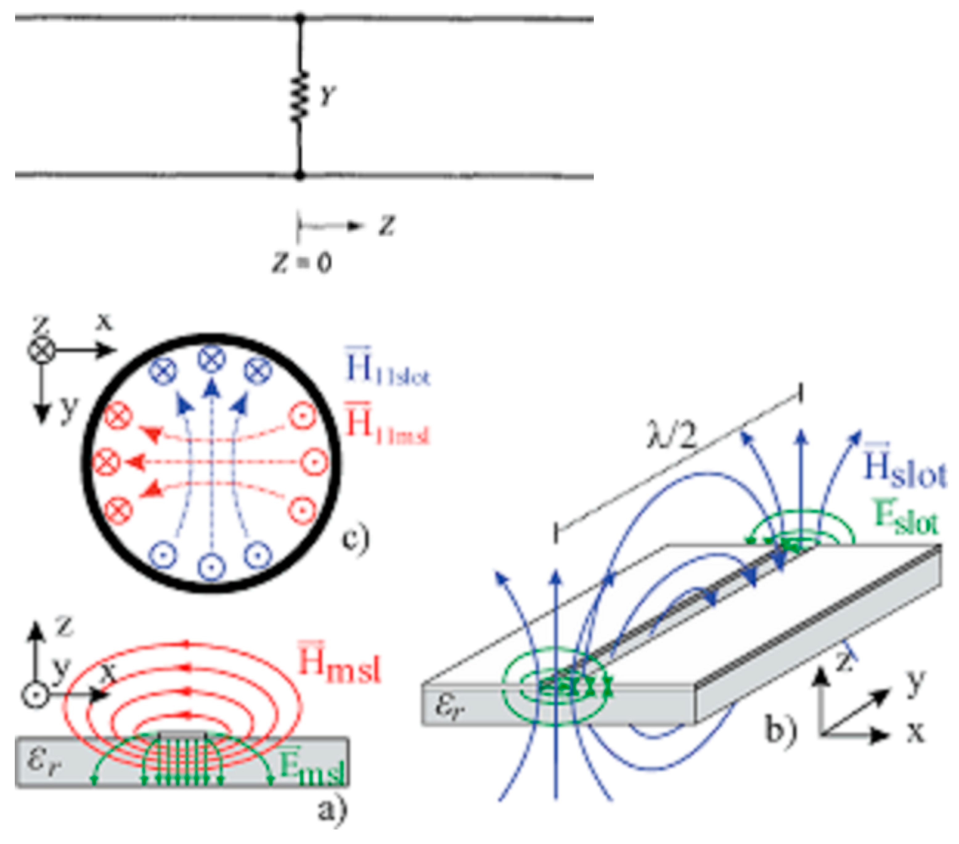
3. Antenna Design and Operation

In order to understand the slotted waveguide antenna, we first need to understand the fields within the waveguides. In a waveguide, we are looking for solutions to Maxell’s equations that are propagating along the guiding direction (the z direction). Thus, the electric and magnetic fields are assumed to have the form
E ˜ x , y , z , t = E ˜ x , y   e i ω t β z   H ˜ x , y , z , t = H ˜ x , y   e i ω t β z
where x , y , z are the spatial coordinates, t is time, E is the electric field, H is the magnetic field, ω is the angular frequency, and β is the propagation wavenumber along the guide direction. The corresponding guide wavelength is denoted by λ g = 2 π / β . It is assumed that the reader is familiar with waveguide mode theory [1], and thus it will be stated without proof that the T E field components in a rectangular guide have the form
H ˜ z = H ˜ a z e i β z E ˜ t = E ˜ a t e i β z H ˜ t = H ˜ a t e i β z .
where a is shorthand for the double index m n (m and n are integers) and
H ˜ a z = cos m π x a cos m π y b z ^ E ˜ a t = i ω μ k c 2 x ^ H ˜ a z y y ^ H ˜ a z x H ˜ a t = i β k c 2 x ^ H ˜ a z x + y ^ H ˜ a z y β = k 2 k c 2 = k 2 m π a 2 n π b 2
where a and b are the dimensions of the waveguide (see Figure 1 below), μ is the magnetic permeability of the material filling the wave guide, k is the free space wave number, and
k c π m a 2 + n b 2
The cutoff frequency of the T E m n mode is expressed by the form
f m n = 1 2 π μ ε m π a 2 + n π b 2 .
where ε is the dielectric susceptibility. The dominant mode fields, T E 10 , are given by
E ˜ 10 , y = i ω μ k c 2 π a sin π x a e i β 10 z H ˜ 10 , x = i β k c 2 π a sin π x a e i β 10 z H ˜ 10 , z = cos π x a e i β 10 z .
Figure 13 shows the waveguide description; the waveguide walls are perfectly conducting, and the dimensions are chosen so that all modes except T E 10 are cut off.
This information needs to be applied to scattering off a slot cut in one of the walls of the waveguide. If the waveguide is assumed to be infinitely long, and a T E 10 mode is launched from z = , traveling in the positive z-direction, the incidence of this mode on the slot will cause backwards and forwards scattering of this mode and radiation into outer space is possible.
Figure 14 shows the geometry of the slot antenna. It is assumed that the waveguide walls have negligible thickness and are composed of a perfect conductor. The slot is rectangular with length 2 l and width w , where 2 l > > w .
The forward and backward scattering off this slot in the T E 10 mode will be [1]
B 10 = x 1 w / 2 x 1 + w / 2 cos ( π x a ) d x l l E 1 x ( z ) e i β 10 z d z ω μ β 10 a b / ( π / a ) 2 C 10 = ( π / a ) 2 cos ( π x 1 a ) l l V ( z ) e i β 10 z d z ω μ β 10 a b .
in which V ( z ) = w E 1 x ( z ) is the voltage distribution in the slot. A slot in a large ground plane can be described as a two-wire transmission line that is fed at the central points; these “wires” are shorted at z = ± l , as shown in Figure 15.
Detailed analysis shows that the voltage distribution in the slot will be a symmetrical standing wave of the form
V ( z ) = V m sin [ k ( l z ) ] .
When inserting (7) in (6), we will obtain
B 10 = C 10 = 2 V m ω μ ( β 10 / k ) a b cos β 10 l cos k l cos ( π x 1 a ) .
It is important to observe that the scattering off the slot is symmetrical, that is, B 10 = C 10 . This implies that the slot is equivalent to a shunt obstacle on a two-wire transmission line. To see this, consider the situation suggested by Figure 16. A transmission line of characteristic admittance G 0 is shunted at z = 0 by a lumped admittance Y .
The voltage and current on the line are given by
V ( z ) = A e i β z + B e i β z z < 0 I ( z ) = A G 0 e i β z B G 0 e i β z V ( z ) = ( A + C ) e i β z z > 0 I ( z ) = ( A + C ) G 0 e i β z .
The boundary conditions are
V ( 0 ) = V ( 0 ) = V ( 0 + ) I ( 0 ) = V ( 0 ) Y + I ( 0 + ) .
Which, when inserted in (9), give
B = C Y G 0 = 2 B A + B .
The usefulness of (11) lies in the fact that, by analogy, if one can find the ratio 2 B 10 / ( A 10 + B 10 ) for the slot, one can then say that the slot has equivalent normalized shunt admittance equal to that ratio.
The slot is said to be resonant if Y / G 0 is pure real. If we take A 10 to be pure real, it follows that the resonant conductance of the slot is given by
G G 0 = 2 B 10 A 10 + B 10 .
where B 10 is pure real also. What this implies is that, for a given displacement x 1 of the slot, it is assumed in (12) that the length 2 l of the slot has been adjusted so that B 10 is either in phase with, or out of phase with, A 10 .
The incident power is given by
p i n c = 1 2 Re S 1 ( A 10 E ˜ 10 , t ×   A 10 H ˜ 10 , t ) z ^ d S 1 = ω μ β 10 a b 4 ( π / a ) 2 A 10 A 10 .
In a similar manner, one finds that the reflected and transmitted powers are
p r e f = ω μ β 10 a b 4 ( π / a ) 2 B 10 B 10 p t r = ω μ β 10 a b 4 ( π / a ) 2 ( A 10 + C 10 ) ( A 10 + C 10 ) .
If use is made of the information that B 10 = C 10 , and that all three amplitudes are pure real, then we can find the expression of the power radiation:
p o w e r   r a d i a t i o n = P i n c P r e f P t r p o w e r   r a d i a t i o n = ω μ β 10 a b 2 ( π / a ) 2 B 10 ( A 10 + B 10 ) .
In [2], it is shown that the impedance relationship between the slot and the complementary dipole is
R r a d d i p o l e R r a d s l o t = η 2 4 .
where η = 377 Ω and R r a d d i p o l e = 73 Ω . By using (16), we can find that R r a d s l o t = 486 Ω . If we express the radiation resistance of the slot by R r a d s l o t = 486 Ω = π η / 4 0.609 , we can find that
P r a d = 1 2 V m 2 R r a d = 0.609 V m 2 2 π η .
Thus,
ω μ β 10 a b 2 ( π / a ) 2 B 10 ( A 10 + B 10 ) = 0.609 V m 2 π η .
If V m is eliminated from (18) and (8), the result is
G G 0 = [ 2.09 ( a / b ) ( β 10 / k ) ( cos β 10 l cos k l ) 2 cos 2 ( π x 1 a ) ] .
When the substitution x = x 1 ( a / 2 ) is made and k l = π / 2 is used, one obtains
G G 0 = [ 2.09 ( a / b ) ( β 10 / k ) cos 2 β 10 k π 2 sin 2 π x a ] .
in which x is the offset from the center line of the broad wall. Equation (20) indicates that the normalized conductance of a resonant longitudinal slot in the broad wall of a rectangular waveguide is approximately equal to a constant times the square of the sine of an angle proportional to its offset. From the point of view of the waveguide, the slot is a shunt impedance across the transmission line or an equivalent admittance loading the transmission line. When the admittance of the slot (or combined admittance of all slots) equals the admittance of the guide, then we have matched the transmission line and the maximum power radiated.
In a similar manner, the circuit model of slotted waveguide antenna is depicted in Figure 17.
The last slot is a distance d from the end (which is shorted-circuited, as seen in Figure 17), and the slot elements are spaced a distance L from each other. The distance between the last slot and the end, d , is chosen to be a quarter-wavelength. Transmission line theory [1] states that impedance of a short circuit a quarter-wavelength down a transmission line is an open circuit, hence, Figure 17 then reduces to Figure 18.
The input admittance for an N element slotted array is:
Y = N Y S .
Sometimes the closed end is spaced 3 4 λ g for mechanical reasons; the additional half-wavelength is transparent. Spacing the slots at 1 2 λ g intervals in the waveguide represents an electrical spacing of 180 : each slot is exactly out of phase with its neighbors, so their radiation will cancel each other. However, slots on opposite sides of the centerline of the guide will be out of phase, so we can alternate the slot displacement around the centerline and have a total phase difference of 360 between slots, putting them back in phase.
A picture of a complete waveguide slot antenna is shown in Figure 19 This example has six slots on each side for a total of twelve slots. The slots have identical length and spacing along the waveguide. Note how the slot position alternates about the centerline of the guide. The far wall of the waveguide has an identical slot pattern, so you can see through the slots.
A simple way to estimate the gain of a slot antenna is to remember that is an array of dipoles. Each time we double the number of dipoles, we double the gain, or add 3 dB. The approximate gain formula is thus G a i n = 10 log ( N )   d B i for N total slots. Ref. [3] gives better formulas for the gain and beam width:
G A I N = 10 log N λ g 2 λ   d B i B e a m w i d t h = 50.7 λ N 2 λ g 2   [ ] .
It is known from [4] that the slot width should be taken as w = λ g 20 . However, measurements taken by Stegen in [5] were based on a slot width of 1.5875 mm in a WR-90 waveguide. For other waveguide sizes, the slot width should be scaled accordingly.

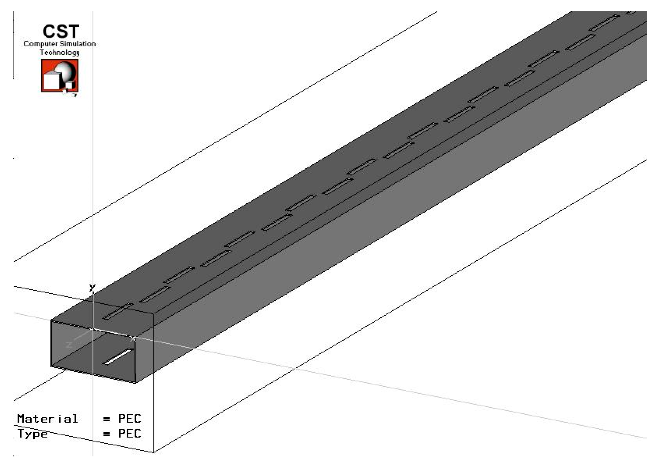
4. Slot Antenna Design and Simulation

We can summarize the design procedure for waveguide slot antenna as follows:
  • Choose the number of slots required for the desired gain and beam width. ( G a i n = 10 log ( N )   d B i so, for a desired gain one can calculate N, and later improve the estimate using Equation (22)).
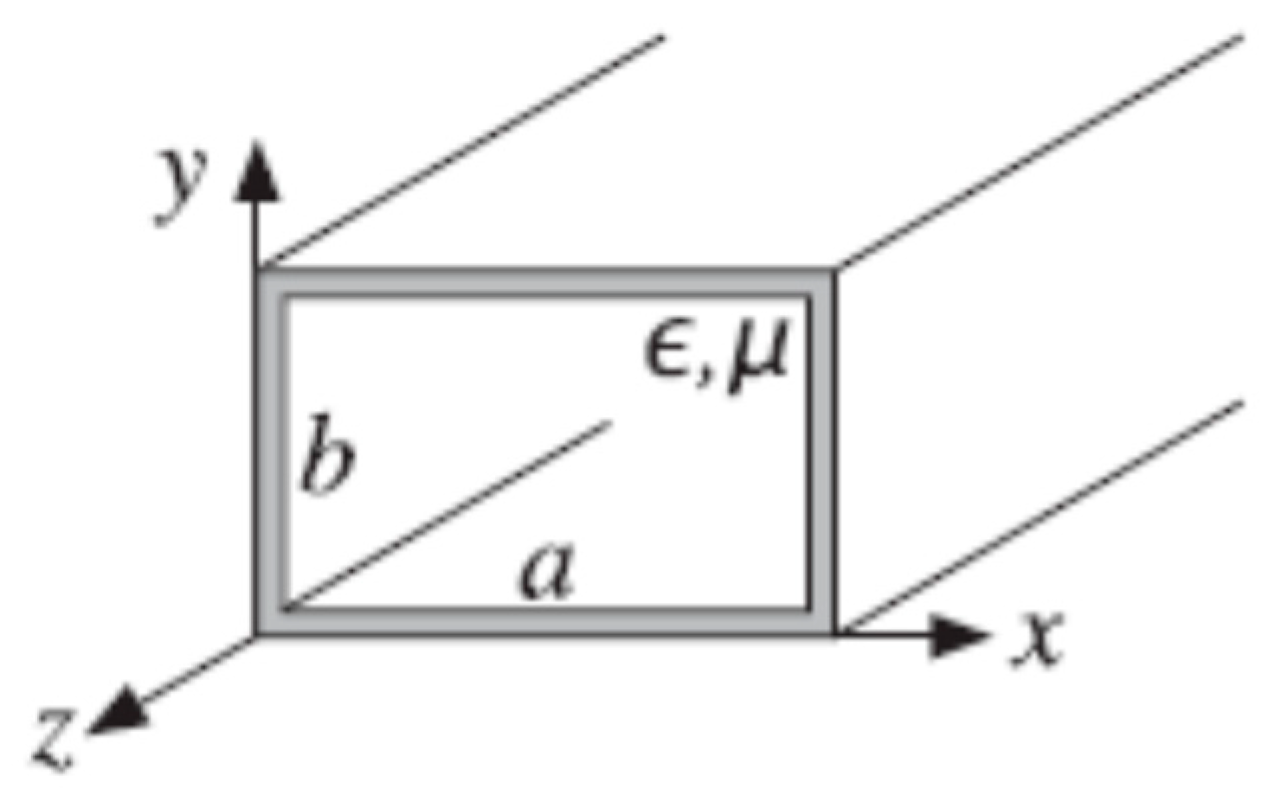
  • Choose a waveguide size appropriate for the operating frequency (see Equations (3), (4) and (23) below for a specific example).
  • Calculate the wavelength in the waveguide at the operating frequency (see Equations (3), (4) and (23) below for a specific example).
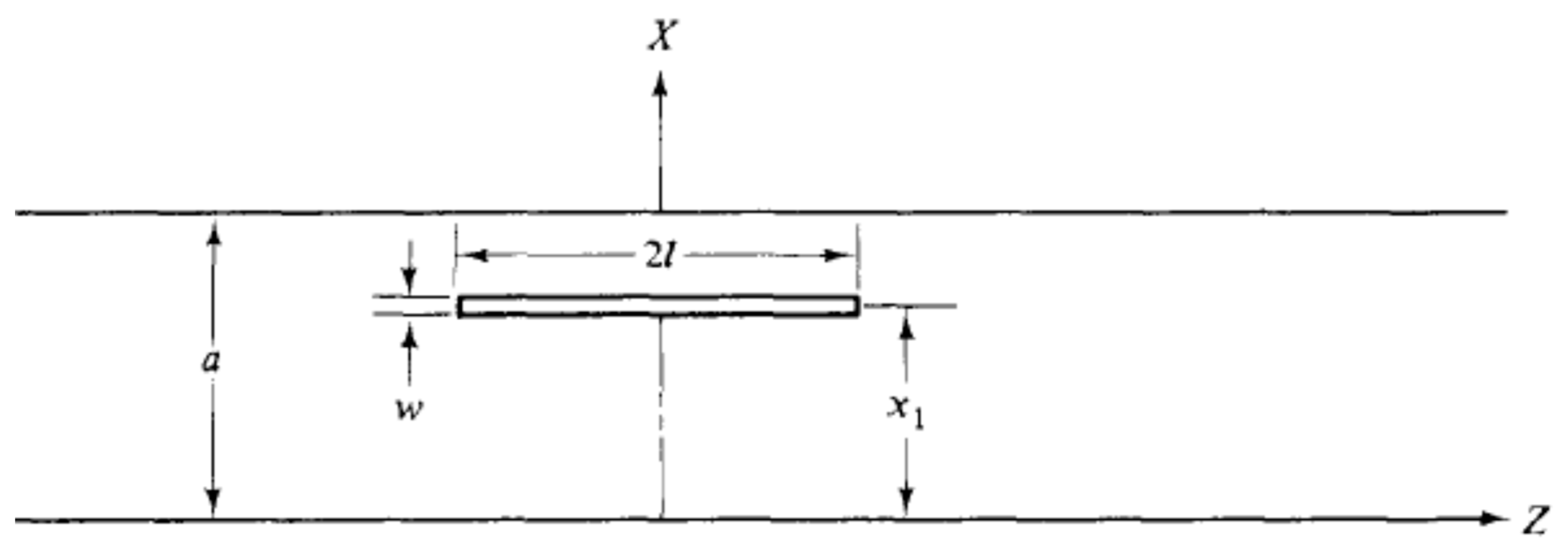
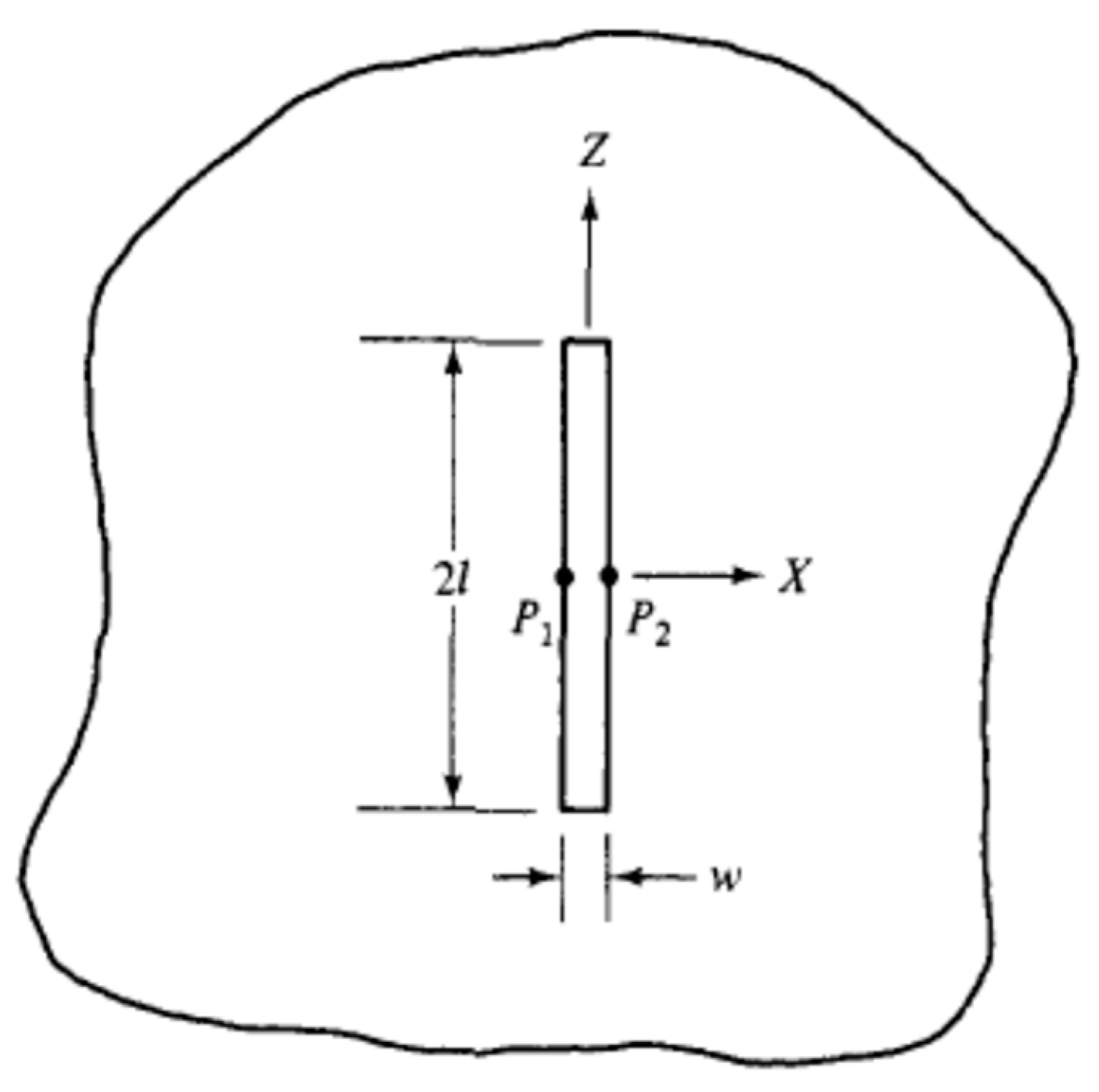
  • Determine the slot dimensions, length, and width appropriate for the operating frequency (see Equation (25) below).
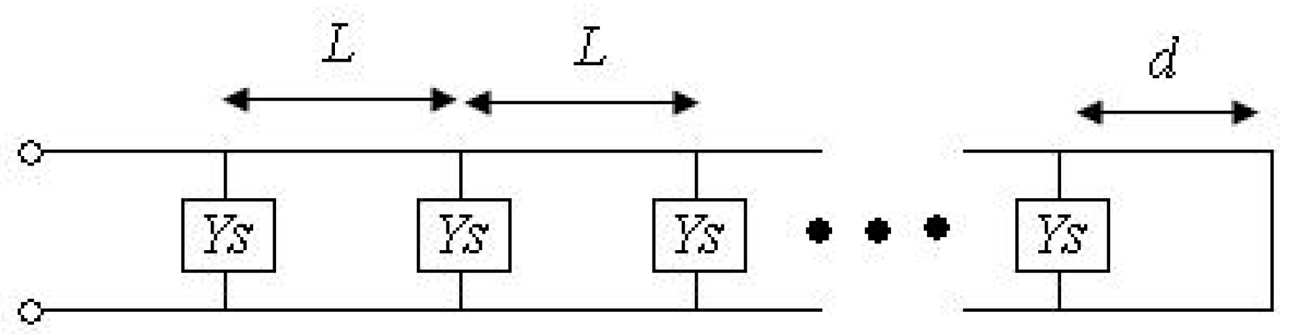
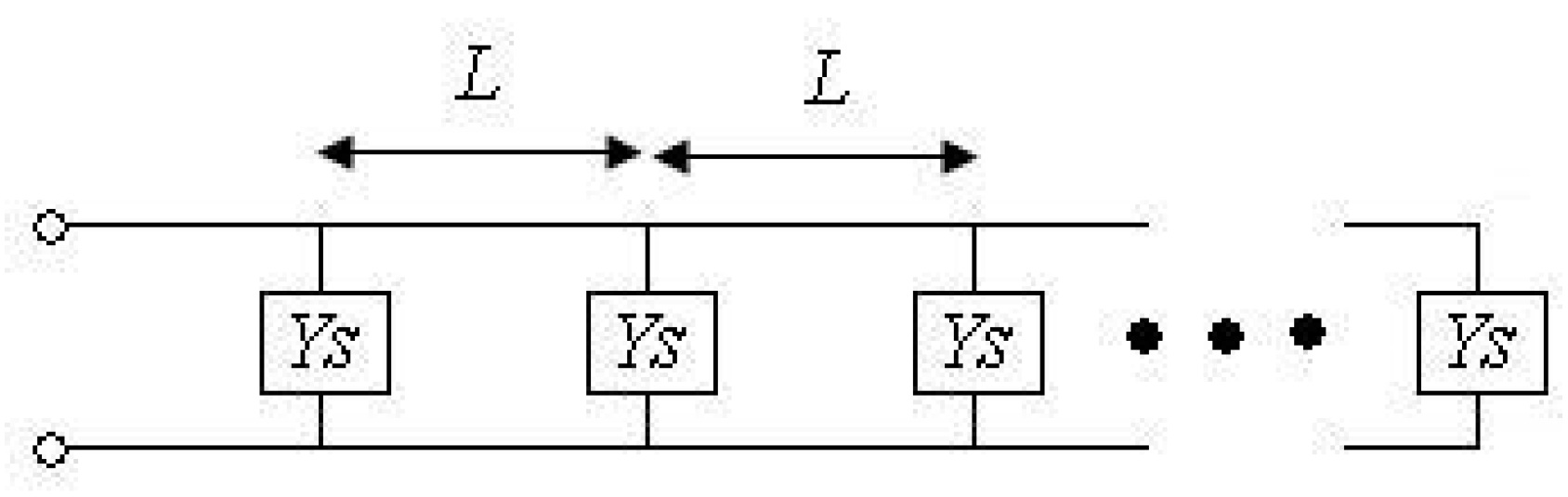
  • Determine the slot position from centerline for normalized admittance of 1/N, where N is the number of slots in both walls of the waveguide (see Equation (26) below).
  • Space 1 4 λ g or 3 4 λ g between the center of the last slot and the end of the waveguide.
For a THz slot antenna design at operation frequency of 330 GHz, the waveguide dimensions are chosen so that all modes except T E 10 are at cut off. The waveguide is WR3 with the dimensions of 0.864 × 0.432 mm2.
The wavelengths are
λ = c f = 0.909 [ m m ] λ c = 2 π k c = 2 π m π a + n π b = 2 a = 1.728 [ m m ] λ g = 1 1 λ 2 1 λ c 2 = 1.07 [ m m ] .
By choosing 256 slots, we will obtain:
G A I N = 10 log N λ g 2 λ =   10 log 256 1.07 2 0.909   = 21.8   d B i B e a m w i d t h = 50.7 λ N 2 λ g 2   = 50.7 0.909 256 2 1.07 2   = 0.7   [ ] .
Thus, the resolution at 10 m is 11.74 [cm].
The slot dimensions are
s l o t _ l e n g t h = 2 l = λ 2 = 0.454 [ m m ] s l o t _ w i d t h = w = λ g 2 = 0.0535 [ m m ] .
The offset from the center line of the broad wall is:
G G 0 = [ 2.09 ( a / b ) ( β 10 / k ) cos 2 β 10 k π 2 sin 2 ( π x a ) ] 1 N = [ 2.09 ( a / b ) ( β 10 / k ) cos 2 β 10 k π 2 sin 2 ( π x a ) ] N [ 2.09 ( a / b ) ( β 10 / k ) cos 2 β 10 k π 2 sin 2 ( π x a ) ] = 1 sin ( π x a ) = 1 N [ 2.09 ( a / b ) ( β 10 / k ) cos 2 β 10 k π 2 ] x = a π arcsin 1 N [ 2.09 ( a / b ) ( β 10 / k ) cos 2 β 10 k π 2 ] x = 0.033   [ m m ] .
Figure 20 and Figure 21 show a model performed using CST Microwave Studio according to the analytical design, the simulation result for the radiation pattern, gain and beam width depicted in Figure 22, Figure 23, Figure 24, Figure 25 and Figure 26.
The simulation results show that the antenna gain is 18.4 dBi and the azimuth beam width is 1.7 compared to 21.8 dBi and 0.7 in the analytical design.
There is a small difference between the analytical and simulation results. The difference is due to the simplifying assumptions that were made in the analytical design (wall thickness was ignored, waveguide length was taken as infinity, etc.). Despite the difference between the analytical and simulation results, a good approximation of the antenna’s performance, pattern, beamwidth, and gain can be made. To conclude the voltage standing wave ratio is given by
V S W R = V m a x V m i n = 1 + Γ 1 Γ
where Γ is the reflection coefficient which is given in Equation (6) through the coefficient B 10 . S 11 is the reflection coefficient if the other side of the wave guide is terminated by a matched load. A plot of B 10 as a function of frequency is given in Figure 27 below.
In addition, the radiated power as a function of frequency is shown in Figure 28 below.
An efficiency of an antenna is defined as
e = R r R r + R l
in which R r is the radiation resistance and R l is the loss (ohmic resistance). Obviously, for a perfect conductor, R l = 0 , and thus e = 1 .

5. Conclusions and Discussion

In this paper, a slot antenna based on a rectangular waveguide has been presented and investigated. It has been shown that a slot antenna in the high THz frequency regime can be analyzed and designed by an analytical model. We show that gradually moving the slot position from the centerline improves the antenna’s performance. This was verified using simulation software. To obtain the required antenna’s pattern and performance, it is first recommended to use an analytical model of the antenna. Using the classical analytical design parameter information, one can perform a simulation. Then, according to the simulation results, the parameters can be modified until optimum results are obtained. We emphasize that, despite the simplicity of our classical approach, the simulation shows that we obtain useful results even at THz frequencies. The relation between radiated power and coefficients is complicated because the parameter V m is obtained by solving Equation (18) and is different for each frequency. Thus, the relation between reflection coefficient and radiated power is not trivial, as can be seen from Figure 27 and Figure 28. The high gain and directivity of this antenna is well described in Figure 22, Figure 23, Figure 24, Figure 25 and Figure 26.
A discussion of other related findings, but at different frequencies, is given in the introductory section.

Author Contributions

Conceptualization, A.Y.; methodology, A.Y.; software, S.R. and A.Y.; validation, S.R.; formal analysis, S.R.; investigation S.R.; resources, A.Y.; data curation, S.R. and A.Y.; writing—original draft preparation, S.R.; writing—review and editing, A.Y.; visualization, S.R.; supervision, A.Y.; project administration, A.Y. All authors have read and agreed to the published version of the manuscript.

Funding

This research received no external funding.

Data Availability Statement

No new data were created or analyzed in this study. Data sharing is not applicable to this article.

Conflicts of Interest

The authors declare no conflict of interest.

References

  1. Collin, R.E. Foundations for Microwave Engineering, 2nd ed.; Mcgraw-Hill College: Columbus, OH, USA, 1992; ISBN 10: 0070118116. [Google Scholar]
  2. Booker, H.G. Slot Aerials and Their Relation to Complementary Wire Aerials. J. IEE 1946, 93, 620–626. [Google Scholar] [CrossRef]
  3. Wade, P. The W1GHZ Online Microwave Antenna Book, Chapter 7. Available online: http://www.w1ghz.org/antbook/preface.htm (accessed on 1 May 2023).
  4. Bell, S. KB7TRZ, Slot Antenna Design. In Proceedings of the 40th Annual West Coast VHF/UHF Conference, Cerritos, CA, USA, 5–7 May 1995; Available online: http://www.qsl.net/w6by/techtips/slot_ant.html (accessed on 1 May 2023).
  5. Stegen, R.J. Longitudinal Shunt Slot Characteristics, Hughes Technical Memorandum No. 261, Culver City, CA. November 1951. Available online: http://www.dtic.mil/dtic/tr/fulltext/u2/a800305.pdf (accessed on 1 May 2023).
  6. Kraus, J. Antennas; McGraw-Hill: Columbus, OH, USA, 1950; pp. 624–642. ISBN 10: 007123201X. [Google Scholar]
  7. Pozar, D.M. Microwave Engineering, 4th ed.; Wiley: New York City, NY, USA, 2011; pp. 65–73. ISBN 10: 0470631554. [Google Scholar]
  8. Chang, K. Encyclopedia of RF and Microwave Engineering; John Wiley & Sons: New York City, NY, USA, 2005; Volume 1–6, pp. 4696–4702. ISBN 978-0-471-27053-9. [Google Scholar]
  9. Elliott, R.S. Antenna Theory and Design; Prentice-Hall: Hoboken, NJ, USA, 1981; pp. 39–41, 86–99, 336–344, 407–414. ISBN 10: 0471449962. [Google Scholar]
  10. Nell, O.; Solbach, K.; Dreier, J. Omnidirectional Waveguide Slot Antenna for Horizontal Polarization. VHF Communications, Part 1: 1991/4, pp. 200–205 and Part 2: 1992/1, pp. 11–17. Available online: http://www.vhfcomm.co.uk/index.html (accessed on 1 May 2023).
  11. Stevenson, A.F. Theory of slots in rectangular waveguides. J. Appl. Phys. 1948, 19, 24–38. [Google Scholar] [CrossRef]
  12. Croswell, W. Slots antenna, Chapter 8. In Antenna Engineering Handbook, 3rd ed.; Johnson, R., Jasik, H., Eds.; McGraw Hill, Inc.: New York, NY, USA, 2007; ISBN 10: 0071475745. [Google Scholar]
  13. Gilbert, R.A. Slot antenna arrays, Chapter 9. In Antenna Engineering Handbook, 3rd ed.; Johnson, R.C., Jasik, H., Eds.; McGraw Hill, Inc.: New York, NY, USA, 2007; ISBN 10: 0071475745. [Google Scholar]
  14. Moradian, M.; Khalaj-Amirhosseini, M.; Tayarani, M. Design of planar slotted array antenna fed by single ridge waveguide. Int. J. RF Microw. Comp. Aid Eng. 2010, 20, 593–602. [Google Scholar] [CrossRef]
  15. Kakatkar, S.S.; Deshmukh, A.A.; Ray, K.P. Analysis of a rectangular waveguide transverse slot using MoM and image method. IET Microw. Antennas Propag. 2020, 14, 1006–1011. [Google Scholar] [CrossRef]
  16. Stein, W.; Deckelmann, M.; Oborovski, A.; Vossiek, M. Planar cross-polarized transition to a circular waveguide feed for a 61 GHz dielectric antenna. In Proceedings of the 2015 German Microwave Conference, Nuremberg, Germany, 16–18 March 2015; pp. 162–165. [Google Scholar] [CrossRef]
  17. Komoshvili, K.; Levitan, J.; Aronov, S.; Yahalom, A.; Kapilevich, B. Millimeter waves non-thermal effect on human lung cancer cells. In Proceedings of the 2011 IEEE International Conference on Microwaves, Communications, Antennas and Electronic Systems (COMCAS 2011), Tel Aviv, Israel, 7–9 November 2011. [Google Scholar] [CrossRef]
  18. Aronov, S.; Einat, M.; Furman, O.; Pilossof, M.; Komoshvili, K.; Ben-Moshe, R.; Yahalom, A.; Levitan, J. Millimeter-wave insertion loss mice skin. J. Electromagn. Waves Appl. 2017, 32, 758–767. [Google Scholar] [CrossRef]
  19. Rajput, S.; Komoshvili, K.; Aronov, S.; Kumar Patnaik, P.; Levitan, J.; Yahalom, A. Optimization of transmitted power of horn antenna for biomedical applications. In Proceedings of the 2019 IEEE International Conference on Microwaves, Antennas, Communications and Electronic Systems (COMCAS), Tel-Aviv, Israel, 4–6 November 2019; pp. 1–4. [Google Scholar] [CrossRef]
  20. Fruman, O.; Komoshvili, K.; Levitan, J.; Yahalom, A.; Liberman-Aronov, S. The Lack of Toxic Effect of High-Power Short-Pulse 101 GHz Millimeter Waves on Healthy Mice. Bioelectromagnetics 2020, 41, 188–199. [Google Scholar] [CrossRef] [PubMed]
  21. Komoshvili, K.; Becker, T.; Levitan, J.; Yahalom, A.; Barbora, A. Liberman-Aronov. S. Morphological Changes in H1299 Human Lung Cancer Cells Following Millimeter-Wave, Irradiation. Appl. Sci. 2020, 10, 3187. [Google Scholar] [CrossRef]
  22. Komoshvili, K.; Levitan, J.; Israely, K.; Yahalom, A.; Barbora, A.; Liberman-Aronov, S. W-Band Millimeter Waves Targeted Mortality of H1299 Human Lung Cancer Cells without Affecting Non-tumorigenic MCF-10A Human Epithelial Cells In Vitro. Appl. Sci. 2020, 10, 4813. [Google Scholar] [CrossRef]
  23. Rajput, S.; Barbora, A.; Komoshvili, K.; Levitan, J.; Yahalom, A.; Liberman-Aronov, S. Scrutinizing Effects of 75 GHz MMW Irradiation on Biological Functions of Yeast. In Proceedings of the 2020 IEEE MTT-S International Microwave Biomedical Conference (IMBioC), Toulouse, France, 25–28 May 2020; pp. 1–4. [Google Scholar] [CrossRef]
  24. Barbora, A.; Rajput, S.; Komoshvili, K.; Levitan, J.; Yahalom, A.; Liberman-Aronov, S. Non-Ionizing Millimeter Waves Non-Thermal Radiation of Saccharomyces Cerevisiae-Insights and Interactions. Appl. Sci. 2021, 11, 6635. [Google Scholar] [CrossRef]
  25. Marks, H.S.; Kleinman, H.; Gover, A.; Einat, M.; Kanter, M.; Borodin, D.; Lasser, Y.; Lurie, Y.; Kapilevich, B.; Litvak, B.; et al. High-Power Long-Pulse Operation of a Millimeter-Wave FEL. In Proceedings of the IPSTA-2014, The 16th Israeli Plasma Science and Applications Conference, Tel Aviv University, Tel Aviv, Israel, 5 February 2014; p. 20. [Google Scholar]
  26. Siegel, P.H. THz Technology: An Overview. Int. J. High Speed Electron. Syst. 2003, 13, 351. [Google Scholar] [CrossRef]
  27. Mickan, S.P.; Zhang, X.-C. T-ray sensing and imaging. Int. J. High-Speed Electron. Sys. 2003, 13, 601. [Google Scholar] [CrossRef]
  28. Siegel, P.H. Terahertz technology. IEEE Trans. Microw. Theory Tech. 2002, 50, 910. [Google Scholar] [CrossRef]
  29. Medvedev, I.; Winnewisser, M.; De Lucia, F.C.; Herbst, E.; Białkowska-Jaworska, E.; Pszczółkowski, L.; Kisiel, Z. The millimeter-and submillimeter-wave spectrum of the trans–gauche conformer of diethyl ether. J. Mol. Spectrosc. 2004, 228, 314–328. [Google Scholar] [CrossRef]
  30. Kemp, M.C.; Taday, P.F.; Cole, B.E.; Cluff, J.A.; Fitzgerald, A.J.; Tribe, W.R. Security applications of terahertz technology. Proc. SPIE 2003, 5070, 44. [Google Scholar]
  31. Balal, N.; Magori, E.; Yahalom, A. Design of a Permanent Magnet Wiggler for a THz Free Electron Laser. Acta Phys. Pol. A 2015, 128, 259–263. [Google Scholar] [CrossRef]
  32. Pinhasi, Y.; Yahalom, A.; Harpaz, O.; Vilner, G. Study of an Ultra Wideband Transmission in the Extremely High Frequency (EHF) Band. IEEE Trans. Antennas Propag. 2004, 52, 2833–2842. [Google Scholar] [CrossRef]
Figure 1. The THz gap in the electromagnetic spectrum.
Electronics 12 02233 g001
Figure 2. THz Image—False Colors. white = metal, red = RDX, orange = candy, green = skin, gray = background, blue = unknown [29].
Electronics 12 02233 g002
Figure 3. Millimeter-Wave Image—produced in the Ariel laboratory.
Electronics 12 02233 g003
Figure 4. Examples of frequency-resolved absorption of explosives and drugs [30].
Electronics 12 02233 g004
Figure 5. Imaging system from Tera View (UK).
Electronics 12 02233 g005
Figure 6. Imaging system from Picometrix (US).
Electronics 12 02233 g006
Figure 7. An image produced by Picometrix.
Electronics 12 02233 g007
Figure 8. Spiricon’s Pyrocam™ III pyroelectric camera.
Electronics 12 02233 g008
Figure 9. Pyrocam™ III sensor array and window assembly.
Electronics 12 02233 g009
Figure 10. Remote detection scheme. Notice that the “mirror” in real-life scenarios is the terrorist’s skin.
Electronics 12 02233 g010
Figure 11. Atmospheric attenuation and phase shift using TRANSM. RH represents the relative humidity, the strongest absorber in normal air. The temperature was assumed to be 17 degrees Celsius. Absorption is given in dB/km.
Electronics 12 02233 g011
Figure 12. Received power through various clothing items. The blue line designates the receiver noise limit. Minimum detectable power Pmin = 3 · 10−11 W as the receiver noise limit. The example is taken at 0.8 THz frequency within the ~0.8 THz transmission band in the atmosphere, equal to a peak in the RDX THz spectrum (40 dB mm−1 at 0.8 THz). Θ = 1.6 · 10−3 steradians. The RDX thickness is 0.1 mm. P0 = 100 mW, allowing fast image acquisition. (a) Ski jacket—width 0, 3, 6, 9 mm. (b) Corrugated cardboard—width 0, 3, 6, 9 mm. (c) Wool sweater—width 0, 3, 6 mm.
Electronics 12 02233 g012
Figure 13. The waveguide description. (https://www.brainkart.com/article/TM-and-TE-waves-in-Rectangular-wave-guides_12511/ (accessed on 1 May 2023)).
Electronics 12 02233 g013
Figure 14. An offset longitudinal slot in the upper broad wall of a rectangular waveguide [1].
Electronics 12 02233 g014
Figure 15. Center-fed slot in a large ground plane [1].
Electronics 12 02233 g015
Figure 16. A shunt obstacle on a two-wire transmission line. Below we show how the electric and magnetic fields behave at the slot (a) x-z cross section (b) a view of the slot from a side perspective (c) magnetic field lines from above. The figure is taken from [16].
Electronics 12 02233 g016
Figure 17. Circuit model of slotted waveguide antenna.
Electronics 12 02233 g017
Figure 18. Circuit model of slotted waveguide using quarter-wavelength transformation.
Electronics 12 02233 g018
Figure 19. Example of waveguide slot antenna.
Electronics 12 02233 g019
Figure 20. Slot antenna model using CST Microwave Studio.
Electronics 12 02233 g020
Figure 21. Slot antenna model using CST Microwave Studio (zoomed in).
Electronics 12 02233 g021
Figure 22. Radiation pattern simulation result.
Electronics 12 02233 g022
Figure 23. Radiation pattern simulation result (x-axis view).
Electronics 12 02233 g023
Figure 24. Radiation pattern simulation result (z-axis view).
Electronics 12 02233 g024
Figure 25. Azimuth radiation pattern simulation result.
Electronics 12 02233 g025
Figure 26. Elevation radiation pattern simulation result.
Electronics 12 02233 g026
Figure 27. | B 10 | reflection coefficient as a function of frequency.
Electronics 12 02233 g027
Figure 28. Radiated power as a function of frequency.
Electronics 12 02233 g028
Table 1. Unique Spectral Lines of Explosives and Drugs (from [30]). Most individual features are robust against the different preparation techniques of these materials (see below).
MaterialFeature Band Center Position Frequency (THz)
Explosives
Semtex-H0.72, 1.29, 1.73, 1.88, 2.15, 2.45, 2.57
PE40.72, 1.29, 1.73, 1.94, 2.21, 2.48, 2.69
RDX/C40.72, 1.26, 1.73
PETN1.73, 2.01, 2.51
HMX1.58, 1.84, 1.91, 2.21, 2.57
TNT1.44, 1.7, 1.91, 5.6, 8.2, 9.1, 9.9
NH4NO34, 7
Drugs
Methamphetamine1.2, 1.7–1.8
MDMA1.4, 1.8
Lactose α-monohydrate0.54, 1.20, 1.38, 1.82, 2.54, 2.87, 3.29
Icing sugar1.44, 1.61, 1.82, 2.24, 257, 2.84, 3.44
Co-codamol1.85, 2.09, 2.93
Aspirin, soluble1.38, 3.26
Aspirin, caplets1.4, 2.24
Acetaminophen6.5
Terfenadine3.2
Naproxen sodium5.2, 6.5
Disclaimer/Publisher’s Note: The statements, opinions and data contained in all publications are solely those of the individual author(s) and contributor(s) and not of MDPI and/or the editor(s). MDPI and/or the editor(s) disclaim responsibility for any injury to people or property resulting from any ideas, methods, instructions or products referred to in the content.

