Article

Road-Network-Based Event Information System in a Cooperative ITS Environment

Department of Smart Vehicle Engineering, Konkuk University, Seoul 05029, Republic of Korea
*
Author to whom correspondence should be addressed.
Electronics 2023, 12(11), 2448; https://doi.org/10.3390/electronics12112448
Submission received: 12 April 2023 / Revised: 17 May 2023 / Accepted: 25 May 2023 / Published: 29 May 2023

Abstract

:
This study proposes and implements an intelligent transportation system (ITS)-based system that collects road event information via a vehicle’s on-board unit (OBU) and roadside unit (RSU), integrates and processes information based on the database and the road network, and provides information to vehicles. This system enables the collection of road unit information without calculating the exact location of event information recognized by the vehicle and facilitates duplicate processing of information recognized from multiple sources. This information can then be provided to other vehicles or road operators via apps or the web, enabling immediate response to emergency situations or changes in road conditions. To verify the practical applicability of this system, we developed a prototype and validated its functions through experiments. Using this system and methods, general drivers, autonomous vehicles, and infrastructure can cooperate in an ITS environment to recognize and propagate various road situations, contributing to the creation of safer and more efficient roads.

1. Introduction

If a driver or autonomous vehicle encounters a sudden road dynamic event, it can lead to an accident that may escalate into a major one involving secondary and tertiary collisions. Road dynamic events, including construction, accidents, bad weathers, and road malfunctions, typically refer to transient dynamic data that can be included in a local dynamic map (LDM; Layer 3) [1]. When a road event occurs, it can lead to congestion on the affected road, which can cause significant inconvenience to road users. It has been reported that for every 7 min delay in accident detection, the resulting queue increases by 1 mile, which intensifies congestion and increases the possibility of a secondary accident [2]. If information about the occurrence of road events is not promptly detected and communicated in real-time to surrounding vehicles, it can trigger further events and impair traffic safety and flow, which can threaten the safety of both drivers and autonomous vehicles.
However, existing intelligent transport systems (ITSs) cannot recognize road events rapidly and easily and such incidents cannot be detected at blind spots. As for human road operator monitoring closed-circuit televisions (CCTVs), the recognition of sudden events is delayed, humans have limited perception ranges, and their perception performance can be affected by equipment quality. Smart CCTVs that automatically recognize road events have been introduced [3]; however, certain issues hinder their perception range and equipment management and their installation and maintenance costs are high. Consequently, the collection of road event information solely through road equipment is limited. Therefore, various methods have been adopted to recognize road events, such as the use of vehicle equipment [4,5], user reports [6], and social networking service (SNS) data [7,8]. As road event information is collected from multiple sources, the integration of heterogeneous data is important.
Herein, we aim to reduce the blind spots in road event recognition in a cooperative ITS (C-ITS) environment through a combination of vehicles and road equipment and then integrate the collected information in a standardized form. ISO/TR 21186 [9] provides guidelines for supporting the interoperability of C-ITSs based on data exchange between vehicles, roadside and urban infrastructure, control and service centers in the cloud, and other road users. Using these elements, we aim to overcome the limitations of existing technologies based on road-equipment and promote the goals of ITSs, namely, safety, efficiency, comfort, and sustainability.
To achieve this, we developed and implemented a system that collects road event information from the on-board units (OBUs) of vehicles and roadside units (RSUs), integrates and monitors the gathered information based on the road network, and provides this information to vehicles. To collect road event information, we assumed that the OBUs of sensor-equipped vehicles automatically recognize event information and upload it to a database and that the road event information from the RSUs is obtained using the open application programming interface (API) of the Korean National Traffic Information Center [10]. To integrate and monitor event information, we used a spatial information database system and road network information in a graph structure composed of standard nodes (or vertices)/links (or edges). We built a cloud-based back-office to automate the information processing and integration processes, communicate with multiple vehicles (data detectors or consumers), and control events on a website. To provide event information, we used a navigation app. We selected roads affected by an event using the road network information (standard nodes/links) stored in the database and ensured that only vehicles on that road received warning notifications.
Herein, we constructed a systematic system based on the cloud, a database, and an API to ensure interoperability between C-ITS components, such as vehicles, infrastructure, road operators, and various devices. Based on the road network, we propose a method for efficiently integrating the road event information collected from multiple vehicles and infrastructure. We devised a way to find the standard link ID of the road where the current location (latitude and longitude) of the vehicle and the event belongs using the database. Through this, we achieved the following.
  • Even without calculating the exact coordinates of an event recognized by a vehicle, it is possible to upload road event information. We solved the problem of difficulty in accurately estimating the location of an object recognized by a camera in a vehicle.
  • Duplicate handling of information simultaneously recognized by multiple vehicles is possible. We solved the problem of difficulty in distinguishing or unifying when an object (road event) is observed from multiple angles and recognized in various coordinates.
  • It is possible to determine traffic congestion based on vehicle travel speed per road standard link. We were able to derive additional meaningful data from the collected vehicle information.
  • It is possible to select vehicles for information provision per road standard link. By providing event information only to vehicles that are actually affected by events, we reduced the provision of unnecessary information and ensured the driver’s freedom of route selection. Additionally, we improved the reliability of the event information provided, preventing the “boy-who-cried-wolf” problem, whereby drivers ignore frequent unreliable event information.
This study is presented in the following order. In Section 2, we present background knowledge about C-ITSs, connected and autonomous vehicles (C-AVs), and road networks. We also review related research on road event recognition and road information systems. In Section 3, we provide an overview of the overall system, the system architecture, and the cloud-based back-office architecture, followed by an explanation of the back-office components. In Section 4, we explain the methods and formats for collecting event information based on vehicle and roadside equipment. In Section 5, we explain the implemented road-network-based event integration and processing algorithm. In Section 6, we describe the implemented technology stack, experimental methods, and experimental results. Finally, in Section 7, we provide our conclusions and suggestions for future improvement.

2. Background and Related Work

In this section, we discuss the background of this study, including C-ITSs, C-AVs, and road networks. We also review related research on road event detection and road information systems.

2.1. C-ITSs and C-AVs

Recent advancements in wireless communication technologies, such as cellular vehicle-to-everything (C-V2X) [11] and wireless access in vehicular environments (WAVE) [12], have led to efforts to implement C-ITSs that operate via vehicle-to-everything (V2X) communication. Standardization and research related to this subject are ongoing [9,13]. C-ITSs represent a paradigm shift from the road management-centric ITS to a driver safety-centric system to anticipate unexpected situations and prevent accidents or congestion. A service that collects and provides information about road events is a crucial function of a C-ITS. With increasing prevalence of autonomous vehicles, ITSs must provide road event information to drivers as well as to autonomous vehicles. Detecting and recognizing events in advance is crucial for the safety of autonomous vehicles. However, the sensors of autonomous vehicles can have blind spots and limited maximum detection ranges, and their performance may degrade in poor weather. C-Avs, which cooperate with C-ITSs to complement sensor limitations [14], are being studied to overcome these limitations in autonomous vehicles’ perception range and performance. According to Yu et al. [15], the collision avoidance system of an autonomous vehicle can conduct path planning or high-level decision-making based on its perceived traffic environment to react to direct stimuli and actively avoid such potentially risky stimuli. Combining ITSs and autonomous vehicles can enhance the event detection of autonomous vehicles and elevate the path-planning and decision-making levels of collision avoidance systems. The current study aims to ensure road safety and efficiency by providing vehicles with integrated event information collected through mutual cooperation between infrastructure, general drivers, C-Avs, and other vehicles in a C-ITS environment.

2.2. Road Network Defined by Standard Nodes/Links

Road event information collected from heterogeneous sources, such as RSUs and vehicle OBUs, must be standardized before being integrated. We used standard nodes/links to integrate the locations of events at the road level. These nodes/links are the basic standards for the real-time exchange of traffic information in South Korea, defined to ensure ITS compatibility and efficient interlinking [16]. Standard nodes/links represent the connection information of roads in the form of a graph [17] made up of link connecting nodes. A node represents a location where a vehicle’s driving speed changes, such as intersections, bridge endpoints, overpass endpoints, road endpoints, underpass endpoints, tunnel endpoints, administrative boundaries, and IC/JC types. A link is a line connecting these nodes, representing real-world roads. Turning restriction information indicates the types and restrictions of turns from one link to another at an intersection. Although multiple links are physically connected to a single node, these links are not logically connected for vehicle movement. Therefore, turning restriction information is used to define logical connections between links.
Standard node/link information and turning restriction information are distributed as shapefile (SHP) files (ESRI ArcView formats *.shp, *.shx, and *.dbf) [18] containing the elements listed in Table 1, Table 2 and Table 3. The Korean National Traffic Information Center updates the standard node/link information and turning restriction information SHP files whenever road attributes change.

2.3. Related Work

2.3.1. Road Event Detection Method

The automatic detection of unexpected incidents from video data is being studied to overcome the limitations of traditional systems where human roadside operators monitor CCTVs [19,20]. The integration of this technology into regular CCTVs, which makes them smart CCTVs, can increase the detection rate of unexpected incidents and reduce the detection time. In studies on RSU-based automatic incident detection (AID), unexpected incidents are primarily detected using fixed CCTVs. However, this technology can be used in the future to detect unexpected incidents using vehicle camera sensors. As the present study is not about deep learning models that detect unexpected incidents from vehicle camera sensors, we used dummy event data for experimentation.
Even if the performance of AID based on road equipment was improved, limitations in incident detection will remain owing to the blind spots of RSUs. Therefore, vehicle-based technologies [4,5] are being explored to collect various information through vehicles operating on roads instead of stationary units, such as CCTVs. Shin et al. [5] recognized dynamic objects from vehicle camera sensors, mapped the positions of these objects onto a grid and uploaded the data to a database. Here, a dynamic object refers to highly dynamic data corresponding to the fourth layer of an LDM [1]. The occupancy grid map used to map dynamic objects is often adopted to create local dynamic object maps in autonomous vehicles and intelligent vehicles [21]. However, applying occupancy grid maps to ITSs makes it difficult to accurately represent roads with ongoing incidents. Therefore, we applied road network information instead of a grid map to obtain detailed information about roads with ongoing incidents, such as the number of affected lanes and the road grade and type and used this detailed information when determining road congestion and providing information to vehicles. Moreover, to achieve a global map that can be integrated and controlled over a wider range than a temporary local map, we collected information about events (transient dynamic data) with a longer duration than local temporary dynamic objects.
CrowdITS [6] is a crowdsourcing-based system that collects incident information through means other than road equipment by accepting user reports. Users report road events, such as construction and incidents, using an ITS app on their smartphones, and this information is processed by the ITS processing server. However, collecting information based on user reports has an associated risk (drivers operating their smartphones while driving), so we assumed herein that incidents are automatically detected using vehicle equipment.
Other methods have been developed to recognize road events, such as the integration of information collected from SNS data [7,8] and accident identification and detection through a combination of time-series analysis of traffic data and machine learning [22]. Additionally, the use of aerial vehicles to recognize events from the sky can be considered. For example, a multiple-aerial-vehicle transportation systems [23] operating based on the robot operating system (ROS) framework can be incorporated into the proposed event detection method. The use of multiple aerial vehicles as detection equipment can further expand the range of event detection and reduce blind spots.

2.3.2. Road Information System

Roy et al. [24] classified traffic information systems into infrastructure-based and infrastructure-less vehicle-to-vehicle (V2V) approaches. Infrastructure-based approaches can have a client–server structure or a peer-to-peer (P2P) structure. Our constructed system is an infrastructure-based approach that has a centralized architecture based on vehicle-to-infrastructure (V2I) communication and has a client–server structure. We first introduce studies that have a similar V2I basis to ours. Lee et al. [25] constructed a decentralized edge-fog-cloud system that collects data from multiple edges (vehicles) to create large-scale, high-precision maps, runs the map creation process on a fog server and integrates and stores the map in a cloud server. Owing to the necessity of collecting large-scale point cloud data in real time from multiple vehicles, the load on the central server was reduced using a fog server between the cloud and the edge. Shin et al. [5] also used a decentralized edge-fog-cloud structure to create a road dynamic object map. Dynamic objects such as pedestrians and vehicles are numerous and have short durations, so they are suitable for use with a decentralized system owing to their high communication volume. Unlike previous researchers who constructed decentralized systems for the real-time collection of large-scale data, we built a centralized back-office system based on cloud services. The transient dynamic data herein does not typically occur frequently, so the number of simultaneously collected data is not large. Therefore, we chose a centralized structure to simplify server construction and management, and we used a single database to maintain data consistency and ensure security. To prevent potential overload in the centralized structure, we stored the image data in a separate image server.
The content-oriented communication (COC) system proposed by Fukumoto et al. [26] for VANETs [27] is an infrastructure-based approach with a P2P structure. Their system can collect and analyze information originally held by vehicles and share the information of each vehicle with the surrounding vehicles. The COC system provides the drivers of the surrounding vehicles with timely information acquired by a specific vehicle about traffic congestion due to vehicular accidents or sudden situations. Similar to the COC system, our method analyzes the acquired data and delivers it to other vehicles as useful content. However, our approach uses a V2I client-server structure to reduce the communication overhead and avoid overloading the P2P communication channel. Furthermore, unlike the COC system, our method does not identify congestion areas owing to specific situations (VANET content-driven communication); instead, it makes judgments using only the location and heading information of each vehicle.
PeerTIS, a traffic information system that uses a P2P overlay based on cellular communication [28] is an infrastructure-less periodic-message approach that is based on cellular communication. This system can be used in urban settings because it reduces the direct communication overhead between vehicles, which is a disadvantage of existing P2P-based traffic information systems. PeerTIS is similar to our proposed system in that it is a traffic information system based on cellular communication. However, we used V2I communication to collect event information nationwide, not a limited range, for the large-scale monitoring of traffic flow. Furthermore, because we only acquired the location coordinates and heading information of vehicles, our method has less communication frequency or overhead than P2P communication.

3. System Architecture and Components

In this section, we provide an overview of the system and its functional architecture and present the cloud services and internal cloud architecture used to build the back-office system. Subsequently, we explain the database and event monitoring center, which are components of the back-office system, and the navigation app, which provides information in conjunction with the database.

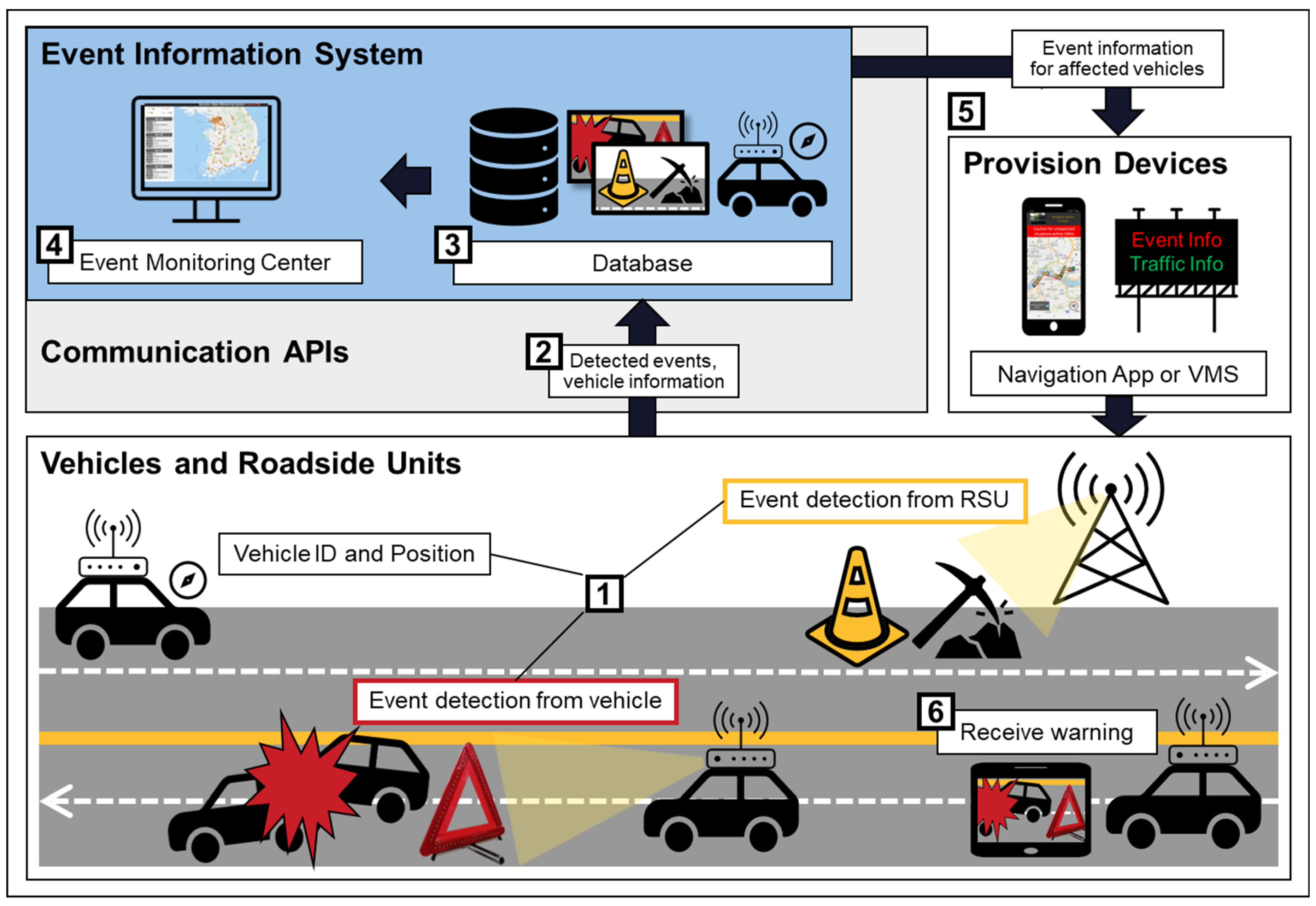
3.1. System Overview

The proposed system for road event information in the C-ITS environment operates using the following process, as shown schematically in Figure 1.
  • Event detection: RSUs, including smart CCTVs, automatically recognize sudden events. Alternatively, operators can identify events through CCTV monitoring or recognize anticipated events (such as demonstrations or forecasted weather conditions). Sensor-equipped vehicles can also automatically recognize sudden events while driving. Additionally, it is assumed that vehicles equipped with devices are aware of their own ID and location information (referred to as detector information).
  • Event information transmission: Road equipment, operators, and equipped vehicles transmit recognized event information with detector information (i.e., detector ID and position) to the database.
  • Event information integration: The database processes, integrates, and stores detector information and event information.
  • Event information monitoring: Operators at a monitoring center oversee the status of sudden events nationwide and handle their closure.
  • Event information provision: Current sudden event information is received from the navigation app server and the RSU server, such as variable message signs (VMS).
  • Event information reception: Sudden event information is provided to vehicles on roads affected by the sudden event through vehicle navigation apps or RSUs installed on the affected road. Target vehicles receive warning messages regarding sudden events that may affect them in the future.

3.2. Overall System Functional Architecture

The proposed environment can be divided into three main components: event detector, event information system, and event information provider. This is presented schematically in Figure 2.
When the event detector recognizes an event, the event information system integrates the event and transmits it to the event information provider. The event detector includes vehicles, such as C-AVs or equipped vehicles, equipped with on-board detection units and RSUs, such as CCTV. The event information system refers to a back-office system based on a cloud database. The event information system comprises a database system that includes one schema and several functions, an event monitoring system implemented on a web server, and a predefined application programming interface (API) for communication between components. The event monitoring web server allows road operators to manage events on a national scale and click a button to terminate completed events. Road operators can detect event termination through various means, such as checking information reported by road users via an app or receiving notifications of construction or accident completion from road managers. The information provider includes RSUs, such as navigation apps or VMS, which can provide warning messages to road users, and various human–machine interface devices may also be included.

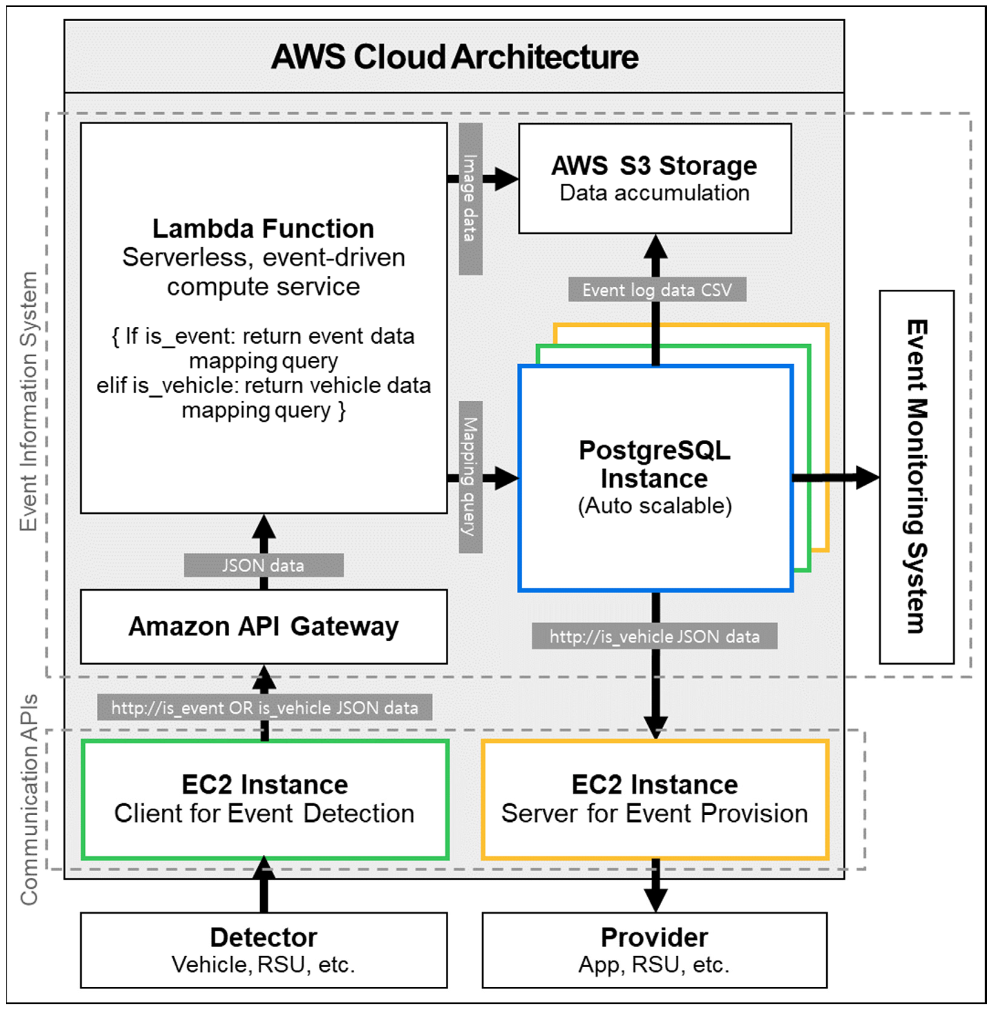
3.3. Cloud System Architecture

The proposed system handles real-time incident data based on open APIs, real-time vehicle information, and national standard node/link data. The amount of data, excluding the standard node/link data, increases or decreases dynamically, depending on the situation and time. However, it cannot be sustained by the on-premises method, which predicts the data processing amount and prepares the server accordingly. Therefore, in this study, a database management system was constructed using the Amazon Web Services (AWS) cloud platform, which can expand or shrink the server according to an increase or decrease in data processing volume. The AWS cloud platform receives and processes the vehicle’s internal data and real-time incident information, and it then delivers it to PostgreSQL for real-time spatial data processing. Information is then stored in AWS S3 to reduce the load on PostgreSQL, which is required for real-time processing. Figure 3 shows the architecture of the AWS cloud system.
The four elements that make up the AWS architecture are as follows:
  • EC2 (elastic compute cloud). Real-time incident data can be queried through the Open API provided by the National ITS Traffic Information Center. To receive real-time data updates, clients who periodically request data from the API server are required. Therefore, to run this client, an EC2 cloud computing service was allocated and built.
  • Amazon API Gateway. Each EC2 client parses its data and requests the lambda function through the Amazon API Gateway. To accommodate this, the API Gateway is configured to save the data in a specified parameter format when it is entered.
  • Lambda function. The lambda function layer operates without a separate server, it processes designated events as they occur. Events are defined as occurrences where vehicle information and real-time incident information access the API Gateway. When this event occurs, the data are passed to the lambda function as a parameter, as defined in 2. The lambda function then maps the parameters to the appropriate query based on whether the event is a vehicle information event or a real-time incident information event and commands PostgreSQL to insert or update the data.
  • PostgreSQL instance and AWS S3. The system was built using PostgreSQL instances allocated through the AWS relational database service. Because read/write operations occur frequently when a new event occurs, the instances are designed to horizontally scale to distribute the load when the specified load is exceeded. Data that is no longer needed in real-time due to the end of an incident or the passage of time is stored in S3 in a timely manner to avoid overloading the database with real-time operations, and it is then deleted from the database.

3.4. Spatial Database System

An auto-scaling PostgreSQL database was built based on AWS. PostgreSQL is an open-source ORDBMS, and PostGIS is a database extension that can be used to process spatial information. PostgreSQL and PostGIS can effectively store and process moving object data, so they are suitable as mobility databases, such as for automobiles [29]. Using the data types and functions provided by PostGIS, the process of processing vehicle information and dynamic event data for a specific road was implemented as an SQL interface and stored in the database with geometric data. At this time, to associate the vehicle and dynamic event data with the road, the standard node/link information of the road must be stored together in a database. However, as standard nodes/links are composed of 3D spatial information files (shapefiles), the original form cannot be stored in a general database. Therefore, for this purpose, PostgreSQL and PostGIS were used to simplify the process of reflecting standard node/link information updates to the database through the QGIS interface.
To standardize the storage of road event information, we designed a database schema comprising five tables, as shown in Figure 4.
The node table has a node ID as a primary key, and multiple links can exist, with a single node as either the starting node (f_node) or the ending node (t_node). In this case, the link has an f_node as a foreign key. In addition, a single node can have multiple turning restriction information, which can be used to determine the turning restriction information of the previous and next links based on the node. The link table has a link ID as a primary key, and multiple events and vehicles can exist on a single link (road). In this case, the events and vehicles have link_id as a foreign key.

3.5. Event Monitoring Web Server

The event monitoring web server receives, visualizes, and manages event information collected countrywide and event API data provided by the Korean National Traffic Information Center. We built a web server using Node.js and Express and displayed a national map using the Naver Map API [30]. Through the communication API, it receives event information from the database and overlays appropriately formatted markers for each event on the map. Using an EventListener, an operator can click on a marker to check the detailed information collected at that point, such as the type of ongoing event, event image, location, and occurrence time. To delete a dynamic event after it finishes, the operator presses the deletion button for the corresponding event marker on the web page and the data is deleted from the database through a communication API request.

3.6. Information Provision App

We developed an information provision app to provide drivers with dynamic event information. We used the T MAP API [31] for basic route guidance and calculated the minimum route from the starting point to the destination. We obtained the link_id of the corresponding path and queried all dynamic events on the expected path before departure, allowing drivers to make necessary preparations, such as modifying the route.
While driving, if any dynamic event data is generated from within a distance set by the driver, a pop-up notification is displayed with a warning and the type of and remaining distance to the dynamic event. Additionally, the link-selection algorithm for the detection of dynamic events was used to provide drivers with dynamic event information to help them prepare for the links they may pass.

4. Event Information Collection Based on Road Network

We collected event data using two methods, vehicle-based equipment and road equipment (i.e., CCTV, RSUs, etc.), and then integrated the collected data.

4.1. Vehicle-Equipment-Based Event Information Collection

4.1.1. Collection Method

Most vehicles currently have Level 2 or 3 advanced driving assistance system functions, which require various sensors, such as forward-facing cameras, radar, and global navigation satellite system modules. As autonomous driving technology advances, more vehicles will be equipped with higher-performance sensors. In this study, it was assumed that the minimum equipment required for collecting sudden event information from the front of the vehicle was a camera, a GPS, and an OBU. As a data collection device for detecting sudden events, an OBU may have an algorithm or weight file of a pretrained artificial intelligence (AI) model. When such a device detects a sudden event, the event information is transmitted to the database via an API. The event attributes are inserted as one record in the dynamic_event table of the database. The algorithm or pretrained AI model in the OBU may recognize various types of event information. This study focuses on the process of handling and integrating event information in the database rather than the quality of event recognition using AI.
Along with the event information, we collected vehicle information at 10-s intervals (which can be adjusted based on network performance). Vehicle information was collected to determine road congestion and extend the potential of the system. The dynamic event information includes detector_id, which indicates the vehicle that recognizes the event. This is intended to provide benefits (such as credits) for using the dynamic event information service when the system is commercially deployed. These benefits would provide an incentive for vehicle users to contribute to the collection of dynamic event information using sensors installed in their vehicles.

4.1.2. Collection Format

The event information is collected in the form shown in Table 4. These attributes include the standard link information attribute of the road for event integration/processing/provision. It also has an image URL attribute because the image server is separated from the database, and images are not uploaded directly to the database. When a sudden event is detected, the vehicle sends the image to the AWS S3 storage, which stores the original image and uploads only the event information to the database. Therefore, the record inserted in the database only includes the URL of the image path stored on the image server. This reduces the load and capacity of the database and optimizes the data transfer speed. The event images stored on the image server can be used for future deep-learning model training.
In addition, the system collects vehicle information in the format shown in Table 5. These attributes are inserted as a single record into the vehicle table of the database and include standard link information, similar to dynamic event information. This differs from dynamic event information in that the system mainly performs updates rather than record insertions. For new vehicles that are not registered with the database, a new record is inserted, while for existing vehicles, the record corresponding to vehicle_id is updated at regular intervals based on the vehicle’s location changes.

4.1.3. Privacy

Privacy protection is a crucial consideration, especially for systems collecting sensitive data such as vehicle IDs and location information. Several methods have been proposed to protect personal information in the road event information system, such as vehicle ID encryption/decryption, a pseudonym change strategy [32], and collection of information only from users who consent to providing personal information. Our method considers privacy by encrypting the vehicle IDs and storing them in the database. It prevents sensitive information from being leaked by decrypting it when necessary, as shown in Figure 5.
We used a simple AES-CBC algorithm [33] with a block size of 16 bytes to encrypt/decrypt vehicle IDs. Encryption is performed using a 32-byte key, and the base64-encoded result is transmitted to and stored in the database. When vehicle ID identification is required, the original data is obtained through decryption. The data loaded from the database is base64 decoded to acquire the encrypted data. The data is then decrypted using the 32-byte key used for encryption.

4.2. Road-Equipment-Based Event Information Collection

The Korean National Traffic Information Center preempts predictable sudden events by collaborating with various agencies, such as the National Police Agency, the Korea Meteorological Administration, and Ministry of Land, Infrastructure and Transport, and other affiliated organizations. They also collect unpredictable sudden event information through CCTV monitoring and some smart-operated CCTVs. This information is publicly disclosed through a real-time sudden event Open API in the form shown in Table 6, and it is updated every minute. The system event information collection server receives real-time public sudden event information through the Open API and requests its insertion into the database event table. The database processes the requested records through duplicate processing of sudden events by link, as defined in this study, and it either inserts or ignores them.

5. Integration and Processing of Event Information Based on Road Network

We developed four algorithms for integrating and processing event information using the road network (standard nodes/links).

5.1. Link-Finding Algorithm

Road event information is always stored in the database with standard link information. When an upsert (update or insert) request for a vehicle or road dynamic event is sent from the API to the database, the database first determines the link of the vehicle or road dynamic event location according to predetermined rules. Then, the determined link ID is added as an attribute to the record, and the update or insert operation is performed.
To determine the vehicle location link, the link closest to the vehicle is chosen from among links where the difference between the link bearing (the GPS bearing between the link start point and end point) and the vehicle heading angle is less than 60°. The link-determination process based on this condition is implemented in PostgreSQL as a function of find_link, a link-finding algorithm, as shown in Figure 6.
When a vehicle detects a road dynamic event at a specific location, the location of the event is assumed to be the vehicle’s location at the time of detection. Therefore, the road dynamic event link is determined by the vehicle link at the time of detection.
As the road dynamic event detected by the vehicle exists in front of the vehicle, there may be an error within the maximum detection range of the vehicle if the event location is defined as the vehicle location. However, the advantage of the proposed method is that the exact location of the road dynamic event is not required because the occurrence link is considered rather than the occurrence location. The link information for the vehicle that detected the road dynamic event includes the direction of travel, so it can be determined whether the event occurred in the upstream or downstream lane. Even if a dynamic road event occurs across the center line in both lanes, it can be conveniently recognized as two separate events in the upstream and downstream lanes without the need to calculate which lane. In addition, since basic road information is included in the link information, it is also useful for managing the road where the road dynamic event occurred.

5.2. Event Duplication Handling

In some cases, multiple vehicles may upload the same event, or the event detected by the vehicle may already exist in the database as a public event (including predictable events). To handle duplicate event detection, when the database receives event information, it first determines the link of the location according to predetermined rules and adds the link ID as an attribute before deciding whether to insert the record into the table. Therefore, because event information always includes link information, duplicate event processing can be implemented at the link level.
The uniqueness of a road dynamic event on a link is determined by the condition that only one road dynamic event of the same event type and event subtype can exist on a single link. This condition is defined by the assumption that, for drivers, the occurrence of a particular type and subtype of road dynamic event on a single road is more important than the total number of occurrences. Based on this condition, the upsert_event function implemented in PostgreSQL ignores a request to insert a road dynamic event into the table if a record with the same link ID, event type, and event subtype already exists.
A similar function, upsert_vehicle, is also implemented to manage the insertion and update of vehicle information in the database. When updating vehicle information in the database, this function updates the record with the new location and heading information if the vehicle ID already exists in the vehicle table, and it inserts the vehicle information as a new record if the vehicle ID does not exist in the vehicle table.

5.3. Congestion Detection Algorithm

To implement a congestion detection algorithm, we used the link detection algorithm, along with the vehicle information stored with the standard link information. When a detected vehicle link differs from a previous one, trigger monitoring of the vehicle information table is called for. The trigger calculates the average speed of the vehicles passing through the link according to a predefined procedure. The average speed information for the link is then added to the record in the link table, and each link table column stores the speed limit information for each road (link). Congestion is then determined by comparing the average speed information obtained from the vehicles with the speed limit information for the road. The procedure for calculating the average speed of vehicles is expressed in Algorithm 1.
Algorithm 1 Congestion Detection
Require: vehicle information with standard link data D
if a change in the D is detected by database trigger then
  if there is not link_entry_time then
   link_entry_time to now
  end if
  if there is a link_entry_time then
   link_avg_spd to (now − link_entry_time) / link_length
  end if
end if

5.4. Selecting Links in the Affected Area

To implement this method, a prev_link_id attribute was added to the link table in advance, and a link list was stored in the prev_link_id attribute for each link starting at the end node. Links that could not be entered due to turning restrictions were excluded from the links connected to each link. When receiving event information, the link where the event occurred is first determined using the link-finding algorithm. Starting with the event occurred link, the algorithm visits the links in the affected area by recursively searching for prev_link until the accumulated distance of the link length exceeds the limit distance parameter. These can be used to provide warning alerts or guide vehicles on new paths for vehicles located on the link (identified by the link_id attribute).

6. Experiment

We have implemented and experimented with a prototype of the proposed system.

6.1. Prototype Implementation

The technical architecture used in the prototype is shown in Figure 7.
We developed a data collection device prototype that can be installed in a typical vehicle as an OBU, as shown in Figure 8. The prototype consisted of a small embedded PC (Jetson Nano), a camera (oCAM-5CRO-U-M), and a GPS sensor (Ublox ZED-F9P). ROS middleware [34] was used to collect sensor data and transmit it to the cloud server.
As it was difficult to install or find enough real-world situations of sudden events, such as road accidents, we detected dummy event information assuming road safety signs as events. For this, we used the weight file obtained by training speed limit signs on the YOLO model [35].

6.2. Experiment Scenario

To simulate an environment where event information is collected from multiple vehicles simultaneously, we split the ROS logging data (rosbag) acquired while driving a single vehicle into four parts, as shown in Figure 9. We used the rosbag to store all data collected from the data collection device in chronological order and to create an environment where four vehicles are driving, we played back four logging data simultaneously. We uploaded the dummy events (safety signs) recognized by these vehicles to the database and made the event information immediately available on the monitoring website and the information provision navigation app for the following vehicles.
The integration and verification scenario for the entire development was as follows:
  • Four vehicles equipped with data collection devices automatically recognize dummy events (safety signs) in the driving environment.
  • The four vehicles send their own information and the recognized event data to the database through the API. (Verification of event information collection function)
  • The database receives event information transmitted in real-time from the vehicles and Open API event information from the National Traffic Information Center, and processes and integrates them using the implemented algorithm. Road operators check the event information in real time on the monitoring website linked to the database. (Verification of event information integration and processing function)
  • One minute after the four lead vehicles start data collection, the following vehicle drives along the same route.
  • The information provision app used in the following vehicle provides event information and warning notifications in connection with the database. (verification of event information provision in 1 min)

6.3. Experiment Results

6.3.1. Results of Event Information Collection and Integration

Figure 10 presents the results of dummy event information collection using the developed data collection device prototype. Figure 10 includes the road dynamic event table in the database. When a virtual event was recognized, the link-finding function found the link_id of the event, the duplication handling function checked for data duplication, and the event information (such as the coordinates, start date, and image path) was uploaded along with the link_id to the database. The original image data was separately stored in the storage. The detector ID, which indicated the vehicle that recognized the event, was encrypted for privacy.
Figure 11 depicts the monitoring web page displaying the overall event information in conjunction with the database. The left screenshot shows the events collected nationwide. The events collected using vehicle equipment in our experiment and public events acquired from the National Traffic Information Center’s Open API were integrated. The middle screenshot mainly shows the events collected by a vehicle equipped with our data collection device. The right screenshot presents an event information pop-up window, which appears when a specific event is clicked.

6.3.2. Event Information Processing Results

Figure 12 shows the query result of events acquired from a specific link_id among the events in the dynamic_event table of the database. Events of the same type acquired from the same road (link) were processed as duplicates, and only events of different types were stored on the same link.
Figure 13 shows the query result of the average vehicle speed obtained by processing the collected vehicle location data, along with the speed limit of some roads (links). All roads (links) shown in Figure 13 have significantly lower average speeds compared with their speed limits. Thus, these roads had high congestion levels.

6.3.3. Event Information Provision Results

Figure 14 shows the navigation app used in the following vehicle, which alerted drivers using the event information collected by our system. The following vehicle started driving a minute after the lead vehicle began traveling. The left screenshot displays the screen where a route is generated using departure and arrival information, where the event information is fetched from the database via the communication API using the link information that constitutes the route. At the start of their drive, a driver is alerted to all events on the entire route. The right screenshot shows the screen where the app, linked with the database, issues an alert to the driver when the vehicle is within a certain distance of an event in the road network during the drive. Therefore, the events detected on the route passed by the lead vehicle were confirmed in the following vehicle within 1 min.

7. Conclusions

We proposed and implemented a system that collects road event information from vehicle OBUs and RSUs based on C-ITS technology, integrates and monitors such information based on a road network, and provides this information to vehicles. The system stores road network information (standard nodes/links) in a database and implements algorithms to process and integrate data using this information. A prototype of the proposed system was implemented, and logging data from various driving routes were simultaneously played back to construct a multivehicle driving environment and test the system. The experiment results confirmed that the event information collected from multiple vehicle and road devices was effectively integrated and stored in the database; furthermore, the algorithms developed for event processing worked properly. In the provision of event information, the entire situation of each event was provided in the web-based monitoring system. Information about sudden events on a driver’s future route was provided in 1 min using the implemented app.
The system built herein is a cloud-based back-office architecture that collects and provides information through V2I cellular communication and APIs. A centralized architecture is used to maintain data consistency and enhance security. Using a road network is advantageous, unlike existing GPS- and grid-based methods; event information can be collected on a road unit basis without calculating the exact coordinates of the event recognized by the vehicle. Duplicates among information obtained from multiple sources are handled well, and links are selected in the affected area using the road connection information. Furthermore, congestion is determined using a lightweight method that adopts road networks and vehicle information. Additionally, encryption and decryption are applied in the process of collecting vehicle information for privacy protection.
The system’s improvement plan includes an enhanced method for handling the conclusion of sudden events and for applying an image-based real-world event detection technology. Currently, road users report the conclusion of sudden events to road operators or road managers, who notify road operators of the end of construction or accident handling. This method does not guarantee real-time detection of the conclusion of events. In the future, technology that continuously monitors the location of ongoing sudden events based on vehicle or road equipment will be required to detect the end of sudden events automatically. Another approach is to predict the duration of sudden events, which is currently being researched, and combine this with the system to accurately handle the conclusion of sudden events. To apply an image-based real-world event recognition method, the data collection device prototype can use a pretrained AI model for road event detection. Ultimately, with such improvements, this proposed system will enable general drivers, autonomous vehicles, and infrastructure to cooperatively identify various situations on roads in the C-ITS environment, making the roads safer and more efficient.

Author Contributions

Conceptualization, K.L. and C.M.; methodology, K.L., D.H. and J.K.; software, K.L., D.H., D.C. and H.C.; validation, K.L. and D.H.; formal analysis, K.L.; investigation, K.L., D.H., J.K., D.C., H.C. and J.M.; resources, C.M.; data curation, D.H. and D.C.; writing—original draft preparation, K.L.; writing—review and editing, K.L., D.H., J.K. and C.M.; visualization, K.L., D.H., D.C. and H.C.; supervision, C.M.; project administration, K.L. and D.H.; funding acquisition, C.M. All authors have read and agreed to the published version of the manuscript.

Funding

This paper was supported by the Korea Institute for Advancement of Technology (KIAT) grant funded by the Korean Government (MOTIE) (P0020536, HRD Program for Industrial Innovation).

Data Availability Statement

Data is available from the authors.

Conflicts of Interest

The authors declare no conflict of interest.

References

  1. ETSI. TR 102 v1.1.1 2011-06 Intelligent Transport Systems (Its); Vehicular Communications; Basic Set of Applications; Local Dynamic Map (ldm); Rationale for and Guidance on Standardization. Available online: https://www.etsi.org (accessed on 24 May 2023).
  2. Chakraborty, P.; Sharma, A.; Hegde, C. Freeway traffic incident detection from cameras: A semi-supervised learning approach. In Proceedings of the 21st International Conference on Intelligent Transportation Systems (ITSC), Maui, HI, USA, 4–7 November 2018; pp. 1840–1845. [Google Scholar] [CrossRef]
  3. An Unexpected Accident on the Road, AI CCTV Finds It and Informs You in 1 Minute [Website]. Available online: https://www.yna.co.kr/view/AKR20200427164700003 (accessed on 24 May 2023).
  4. Gokasar, I.; Timurogullari, A.; Özkan, S.S.; Deveci, M.; Lv, Z. MSND: Modified standard normal deviate incident detection algorithm for connected autonomous and human-driven vehicles in mixed traffic. IEEE Trans. Intell. Transp. Syst. 2022, 1–10. [Google Scholar] [CrossRef]
  5. Shin, S.; Kim, J.; Moon, C. Road dynamic object mapping system based on edge-fog-cloud computing. Electronics 2021, 10, 2825. [Google Scholar] [CrossRef]
  6. Ali, K.; Al-Yaseen, D.; Ejaz, A.; Javed, T.; Hassanein, H.S. CrowdITS: Crowdsourcing in intelligent transportation systems. In Proceedings of the 2012 IEEE Wireless Communications and Networking Conference (WCNC), Paris, France, 1–4 April 2012; pp. 3307–3311. [Google Scholar] [CrossRef]
  7. Rettore, P.H.L.; Santos, B.P.; Lopes, R.R.F.; Maia, G.; Villas, L.A.; Loureiro, A.A.F. Road data enrichment framework based on heterogeneous data fusion for ITS. IEEE Trans. Intell. Transp. Syst. 2020, 21, 1751–1766. [Google Scholar] [CrossRef]
  8. Ishigami, K.; Enoki, M.; Oguchi, M. Event Information Search Method from SNS Data considering Privacy of User’s Location Information. In Proceedings of the 2022 IEEE International Conference on Smart Computing (SMARTCOMP), Helsinki, Finland, 20–24 June 2022; pp. 240–245. [Google Scholar] [CrossRef]
  9. ISO/TR 21186-1:2021(en); Cooperative Intelligent Transport Systems (C-ITS)—Guidelines on the Usage of Standards—Part 1: Standardization Landscape and Releases. ISO: Geneva, Switzerland, 2021.
  10. Korean National Transport Information Center [Website]. (n.d.). Available online: https://www.its.go.kr/opendata/ (accessed on 24 May 2023).
  11. Chen, S.; Hu, J.; Shi, Y.; Zhao, L.; Li, W. A vision of C-V2X: Technologies, field testing, and challenges with Chinese development. IEEE Internet Things J. 2020, 7, 3872–3881. [Google Scholar] [CrossRef]
  12. Uzcátegui, R.A.; De Sucre, A.J.; Acosta-Marum, G. Wave: A tutorial. IEEE Commun. Mag. 2009, 47, 126–133. [Google Scholar] [CrossRef]
  13. Festag, A. Cooperative intelligent transport systems standards in Europe. IEEE Commun. Mag. 2014, 52, 166–172. [Google Scholar] [CrossRef]
  14. Gerla, M.; Lee, E.K.; Pau, G.; Lee, U. Internet of vehicles: From intelligent grid to autonomous cars and vehicular clouds. In Proceedings of the IEEE World Forum on Internet of Things (WF-IoT), Seoul, Republic of Korea, 6–8 March 2014; pp. 241–246. [Google Scholar] [CrossRef]
  15. Yu, Y.; Shan, D.; Benderius, O.; Berger, C.; Kang, Y. Formally Robust and Safe Trajectory Planning and Tracking for Autonomous Vehicles. IEEE Trans. Intell. Transp. Syst. 2022, 23, 22971–22987. [Google Scholar] [CrossRef]
  16. Introducing Node/Link [Website]. (n.d.). Available online: https://www.its.go.kr/nodelink/ (accessed on 24 May 2023).
  17. Phillips, J.D.; Schwanghart, W.; Heckmann, T. Graph theory in the geosciences. Earth Sci. Rev. 2015, 143, 147–160. [Google Scholar] [CrossRef]
  18. ESRI. (July 1998). ESRI Shapefile Technical Description. Available online: http://www.esri.com/library/whitepapers/pdfs/shapefile.pdf (accessed on 24 May 2023).
  19. Weil, R.; Wootton, J.; García-Ortiz, A. Traffic incident detection: Sensors and algorithms. Math. Comput. Model. 1998, 27, 257–291. [Google Scholar] [CrossRef]
  20. Thakare, K.V.; Dogra, D.P.; Choi, H.; Kim, H.; Kim, I.J. Object interaction-based localization and description of road accident events using deep learning. IEEE Trans. Intell. Transp. Syst. 2022, 23, 20601–20613. [Google Scholar] [CrossRef]
  21. Schreier, M.; Willert, V.; Adamy, J. Grid mapping in dynamic road environments: Classification of dynamic cell hypothesis via tracking. In Proceedings of the 2014 IEEE International Conference on Robotics and Automation (ICRA), Hong Kong, China, 31 May–7 June 2014; pp. 3995–4002. [Google Scholar] [CrossRef]
  22. Wang, J.; Li, X.; Liao, S.S.; Hua, Z. A sshybrid approach for automatic incident detection. IEEE Trans. Intell. Transp. Syst. 2013, 14, 1176–1185. [Google Scholar] [CrossRef]
  23. Yu, Y.; Shi, C.; Shan, D.; Lippiello, V.; Yang, Y. A hierarchical control scheme for multiple aerial vehicle transportation systems with uncertainties and state/input constraints. Appl. Math. Model. 2022, 109, 651–678. [Google Scholar] [CrossRef]
  24. Roy, B.; Patnaik, S.; Dutta, P. Congestion Detection Techniques in Road Network. In Proceedings of the 2021 Smart City Challenges & Outcomes for Urban Transformation (SCOUT), Bhubaneswar, India, 25–26 December 2021; pp. 252–255. [Google Scholar] [CrossRef]
  25. Lee, J.; Lee, K.; Yoo, A.; Moon, C. Design and Implementation of Edge-Fog-Cloud System through HD Map Generation from LiDAR Data of Autonomous Vehicles. Electronics 2020, 9, 2084. [Google Scholar] [CrossRef]
  26. Fukumoto, J.; Sirokane, N.; Ishikawa, Y.; Wada, T.; Ohtsuki, K.; Okada, H. Analytic method for real-time traffic problems by using Contents Oriented Communications in VANET. In Proceedings of the 2007 7th International Conference on ITS Telecommunications, Sophia Antipolis, France, 6–8 June 2007; pp. 1–6. [Google Scholar] [CrossRef]
  27. Ku, I.; Lu, Y.; Gerla, M.; Gomes, R.L.; Ongaro, F.; Cerqueira, E. Towards software-defined VANET: Architecture and services. In Proceedings of the 2014 13th Annual Mediterranean Ad Hoc Networking Workshop (MED-HOC-NET), Piran, Slovenia, 2–4 June 2014; pp. 103–110. [Google Scholar]
  28. Rybicki, J.; Scheuermann, B.; Koegel, M.; Mauve, M. Peertis: A peer-to-peer traffic information system. In Proceedings of the Sixth ACM International Workshop on VehiculAr InterNETworking, VANET’09, Beijing, China, 25 September 2009; ACM: New York, NY, USA, 2009; pp. 23–32. [Google Scholar] [CrossRef]
  29. Zimányi, E.; Sakr, M.; Lesuisse, A. MobilityDB: A mobility database based on PostgreSQL and PostGIS. ACM Trans. Database Syst. 2020, 45, 1–42. [Google Scholar] [CrossRef]
  30. NAVER Maps API Overview [Website]. (n.d.). Available online: https://guide.ncloud-docs.com/docs/en/naveropenapiv3-maps-overview (accessed on 24 May 2023).
  31. T Map API [Website]. (n.d.). Available online: https://tmapapi.sktelecom.com/index.html (accessed on 24 May 2023).
  32. Escher, S.; Sontowski, M.; Berling, K.; Köpsell, S.; Strufe, T. How well can your car be tracked: Analysis of the European C-ITS pseudonym scheme. In Proceedings of the 2021 IEEE 93rd Vehicular Technology Conference (VTC2021-Spring), Helsinki, Finland, 25–28 April 2021; pp. 1–6. [Google Scholar] [CrossRef]
  33. Frankel, S.; Glenn, R.; Kelly, S. The AES-CBC Cipher Algorithm and Its Use with IPsec (No. rfc3602); RFC Editor: USA, 2003; Available online: https://www.rfc-editor.org/rfc/rfc3602 (accessed on 10 April 2023).
  34. Quigley, M.; Gerkey, B.; Conley, K.; Faust, J.; Foote, T.; Leibs, J.; Berger, E.; Wheeler, R.; Ng, A. ROS: An open-source Robot Operating System. In Proceedings of the ICRA Workshop on Open Source Software, Kobe, Japan, 12–17 May 2009. [Google Scholar]
  35. Tian, Y.; Yang, G.; Wang, Z.; Wang, H.; Li, E.; Liang, Z. Apple detection during different growth stages in orchards using the improved YOLO-V3 model. Comput. Electron. Agric. 2019, 157, 417–426. [Google Scholar] [CrossRef]
Figure 1. Overview of the event information system in C-ITS environment. Each process is numbered for reference: (1) Event detection, (2) Event information transmission, (3) Event information integration, (4) Event information monitoring, (5) Event information provision, and (6) Event information reception.
Electronics 12 02448 g001
Figure 2. Overall system functional architecture. API; application programming interface.
Electronics 12 02448 g002
Figure 3. Amazon web services (AWS) cloud system architecture. RSU; roadside unit, API; application programming interface.
Electronics 12 02448 g003
Figure 4. Entity relationship diagram of the road event information database. The symbols in the diagram denote specific cardinalities; a circle represents zero possible instances of an entity, while a branched line symbolizes the possibility of multiple instances. PK; primary key which is unique for each record in a database table, FK; foreign key which is a field in one table and a primary key in another table.
Electronics 12 02448 g004
Figure 5. Data encryption-decryption.
Electronics 12 02448 g005
Figure 6. Link-finding algorithm. The alphabets A-C represent arbitrary link IDs.
Electronics 12 02448 g006
Figure 7. Technical architecture used in the prototype.
Electronics 12 02448 g007
Figure 8. Data collection device.
Electronics 12 02448 g008
Figure 9. Experiment route, divided into four parts as represented by the numbers 1–4. The Korean terms represent various place names in Korea.
Electronics 12 02448 g009
Figure 10. Event information stored in the database and images stored in the storage. The event link id determined by the link-finding algorithm is stored along with the event information. The Korean terms represent various place names in Korea.
Electronics 12 02448 g010
Figure 11. The monitoring web page displaying overall event information in conjunction with the database. The Korean terms represent various place names in Korea.
Electronics 12 02448 g011
Figure 12. The result of querying events stored through duplicate handling.
Electronics 12 02448 g012
Figure 13. The result of querying road congestion status on a link basis.
Electronics 12 02448 g013
Figure 14. Screenshots of event information provision app used in the following vehicle. The Korean terms represent various place names in Korea.
Electronics 12 02448 g014
Table 1. Node features.
Attribute NameAttribute Domain
NODE_IDNode id
NODE_TYPENode type code
NODE_NAMENode name
TURN_PTurn restrictions true/false
REMARKNote
COORDINATESNode geometry
Table 2. Link features.
Attribute NameAttribute Domain
LINK_IDLink id
F_NODEStart node id
T_NODEEnd node id
LANESNum of lanes
ROAD_RANKRoad rank code
ROAD_TYPERoad type code
ROAD_NORoad number
ROAD_NAMERoad name
ROAD_USERoad use true/false
MULTI_LINKMultilink true/false
CONNECTConnect roads true/false
MAX_SPDMax speed
REST_VEHRestricted vehicle code
REST_WRestricted weight
REST_HRestricted height
LENGTHLink length
REMARKNote
Table 3. Turning restriction features.
Attribute NameAttribute Domain
NODE_IDNode id
TURN_IDTurn restriction id
ST_LINKStart link id
ED_LINKEnd link id
TURN_TYPETurn-type code
TURN_OPERTurn operation code
REMARKNote
Table 4. Event information table.
Attribute NameAttribute Domain
EVENT_TYPEEvent type
EVENT_DETAIL_TYPEEvent detail type
LINK_IDDetected link id
START_DATEStart date
END_DATEEnd date
COORDINATESDetected position
IMAGE_PATHSaved image path in the image server
DETECTOR_IDEvent detector id
Table 5. Vehicle information table.
Attribute NameAttribute Domain
VEHICLE_IDVehicle id
COORDINATESVehicle position (latitude, longitude, altitude)
HEADINGVehicle GPS heading
LINK_IDCurrent coordinate link id
LINK_START_TIMECurrent link entry time
PREV_LINK_START_TIMEPrevious link entry time
PREV_LINK_IDPrevious link id
Table 6. Event information table from the National Traffic Information Center.
Attribute NameAttribute Domain
TYPERoad type
EVENT_TYPEEvent type
EVENT_DETAIL_TYPEEvent detail type
START_DATEStart date
END_DATEEnd date
COORD_XLongitude
COORD_YLatitude
LINK_IDLink id
ROAD_NAMERoad name
ROAD_NORoad number
ROAD_DRC_TYPERoad direction type
LANES_BLOCK_TYPELane block type
LANES_BLOCKEDLanes blocked
MESSAGEEvent message
Disclaimer/Publisher’s Note: The statements, opinions and data contained in all publications are solely those of the individual author(s) and contributor(s) and not of MDPI and/or the editor(s). MDPI and/or the editor(s) disclaim responsibility for any injury to people or property resulting from any ideas, methods, instructions or products referred to in the content.

