

Low-Profile Wideband Dual-Polarized Patch Antenna Based on Differential-Paired Multi-Mode Arms
1
School of Electronic and Information Engineering, South China University of Technology, Guangzhou 510006, China
2
School of Electronics and Information Engineering, Harbin Institute of Technology (Shenzhen), Shenzhen 518055, China
3
Guangdong Provincial Key Laboratory of Aerospace Communication and Networking Technology, Harbin Institute of Technology (Shenzhen), Shenzhen 518055, China
4
Peng Cheng Laboratory, Shenzhen 518055, China
*
Author to whom correspondence should be addressed.
Electronics 2023, 12(12), 2604; https://doi.org/10.3390/electronics12122604
Submission received: 8 April 2023
/
Revised: 17 May 2023
/
Accepted: 18 May 2023
/
Published: 9 June 2023
(This article belongs to the Special Issue Broadband Antennas and Antenna Arrays)
Abstract
:This paper presents a low-profile wideband, dual-polarized patch antenna using differential-paired, multi-mode arms. By employing the arrow-shaped, differential-paired arms, three modes of them are excited simultaneously, leading to a broad bandwidth. The shorting pins are uniquely inserted at the wings of the arms to obtain stable radiation patterns. Then, two pairs of arms are structured like the dipoles and a dual-polarized antenna is designed. In addition, by employing coplanar coupling feeding structures, a good wideband impedance matching is also achieved without increasing the height. For demonstration, a wideband dual-polarized patch antenna is designed and measured. Benefitting from the advantages of the multi-mode patch and symmetrical structure as a dipole antenna, the proposed dual-polarized antenna operates between 2.10–3.95 GHz, possessing a 10-dB impedance bandwidth of 61%, a profile of 0.1λ0, an average gain of 7.31 dBi, and stable radiation patterns.
1. Introduction
In the wireless communication systems, dual-polarized antennas are widely used for the suppression of multipath fading and the improvement of the channel capacity. The wideband performance with a stable radiation pattern is required to cover the multiple working frequency ranges. In another aspect, the low-profile characteristic is attractive to make the communication equipment more compact and easier to integrate. However, the low profile of the antenna limits the extension of bandwidth that would not meet the requirements. Thus, a lot of researchers have paid attention on the wideband dual-polarized antennas with low profiles.
In the past decades, two categories of dual-polarized antennas have been mainly developed and employed for communication purposes: dual-polarized patch antennas [1,2,3,4,5,6,7,8,9,10,11,12,13,14,15,16] and dual-polarized dipole antennas [17,18,19,20,21,22,23,24,25,26,27,28]. Dual-polarized patch antennas have become notable candidates for compact systems due to their low-profile specifications. However, their bandwidths are relatively narrow. To obtain the broadband characteristic, many efforts have been made: exciting multiple modes [1,2,3], employing L-probe feeding structures [4,5,6], and using stacked patches [7,8,9]. Specifically, shorting pins and slots are utilized in [2] to shift TM10 and TM30 modes closely, contributing to a 13% bandwidth within the profile of 0.029λ0 (where λ0 is the free-space wavelength at the center frequency). L-probe feeding is a typical approach to increase bandwidth since it can add extra capacitance to compensate for the inductance of the probe. For instance, in [4], the antenna with L-probe feeding realizes 54% bandwidth (SWR < 2) with the profile of 0.23λ0. For the stacked patches, by introducing a parasitic patch as an additional resonant element, the antenna has a 57% bandwidth with the profile of 0.27λ0 in [9]. Hence, the above-mentioned studies suggest that increasing bandwidth would lead to an increase in the profile. Recently, a coplanar L-strip fed patch antenna in [10] was developed. Compared with traditional L-probe feedings [4], the horizontal feeding line of the L-strip is printed on the same plane as the patch. Therefore, the coplanar L-strip fed antenna does not enhance the profile. However, it owns a single polarization and its bandwidth is only 41%.
Dipole antennas [17,18,19,20,21,22,23,24,25,26,27,28] are the other type of dual-polarized antennas that are commonly used in communications. Their typical heights are 0.25λ0. For miniaturization, various research has focused on the reductions of the profile [20,21,22]. Introducing an artificial magnetic conductor (AMC) [20,21] and using a nonuniform metasurface [22] are available methods. By using an AMC reflector, the reflected wave is in phase with the incident wave within a certain frequency range, and the antenna in [21] realizes 54.8% bandwidth within the 0.13λ0 height. In [22], the nonuniform metasurface consists of inductive rectangular loops. It brings strong impedance matching in the bandwidth of 33% with a profile of 0.1λ0. Although the profile of the antenna with nonuniform metasurface is much lower than the traditional dipole antennas, the bandwidth is narrower than that of 45% in [18]. The low-profile design of dipole antennas tends to sacrifice the bandwidth. Therefore, it is worth investigating wideband dual-polarized antennas with low profiles.
From the above mentioned dual-polarized antennas of patch and dipoles, it can be found that the patch antenna has the advantage of low profile. Many methods are applied to widen the bandwidth and the high profile follows. The dipoles have a relatively high profile and the bandwidths are wider than patch antennas. The decrease of the dipoles’ height is usually followed by the reduction of the bandwidth. Thus, designing a wide band dual-polarized antenna with a low profile is very challenging.
In this paper, a wideband dual-polarized patch antenna based on differential paired arms is proposed. It combines the configuration of the dipole which has two differential arms and the working principle of multi-mode patch antennas. By uniquely designing the patch shape and the positing vias, three modes are excited successfully with stable patterns. Because of the excitation of the three modes, the bandwidth is extended accordingly. To match the arm in a wide bandwidth, the coplanar coupling feed is adopted. After obtaining the wide band arm, the dual-polarized antenna is constructed by two differential arms, such as the dipoles. The proposed dual-polarized antenna achieves a profile of 0.1λ0, bandwidth of 61%, steady gain, and consistent and symmetrical radiation patterns. The bandwidth of the proposed antenna is wider than the reported works with the same profile [14,15].
2. Antenna Design
Inspired by the symmetrical structure and differentially feeding of the dipole antennas, a novel wideband patch antenna is designed. The proposed antenna has a wide bandwidth and symmetrical radiation patterns. Meanwhile, the profile is relatively low.
2.1. Antenna Configuration
Figure 1 shows the configuration of the proposed antenna, which is composed of two pairs of differential-feeding arms, a square ground, and a feeding network, and they are located in three different layers. The upper layer consists of two radiation arm pairs, i.e., horizontal and vertical pairs. The length and the width of the aims are L1 and W1, respectively. Each pair is differentially fed. The arms are specially designed as an arrow shape, where the length and width of the rectangular corner are L4 and W4, respectively. On each arrow-shaped arm, there are two shorting pins in the wings. The distance between the shorting pin to the edge of the arrow-shaped arm is S1. Additionally, there is a rectangular slot with dimensions of L2 × W2 on the arrow-shaped arm, and a thin, rectangular, feeding line with dimensions of L3 × W3 is coupled to the arm through the slot. The feeding line is connected to the bottom-layer of the feeding network by a metallic pin near the center of the feeding line. The middle layer is employed as the square ground. The substrate with a permittivity of 2.2 and a loss tangent of 0.001 is used between the two layers. The differential feeding network is placed on the bottom layer with a permittivity of 3.38 and a loss tangent of 0.0009.
2.2. Tri-Mode Excitation on Each Arm (Arm I~Arm III)
Since the antenna consists of two pairs of symmetrical differential arms, to be simplified, only one of the arms is analyzed and the evolution is analyzed in Figure 2. Arm I is a traditional rectangular patch with a width W1 and a length of L1. Then, two corners are chamfered to excite another mode, arriving in Arm II. Arm III is an arrow-shaped patch, wherein two rectangular corners are clipped to adjust the resonant frequency. In comparison to Arm III, two shorting pins are placed at the arrow-shaped arm’s wings to obtain the consistent radiation gains at the zenith and it is named Arm IV.
Because Arm I is a conventional patch, by adjusting the width and length to be about half of the guided wavelength at 2.9 GHz and one guided wavelength at 3.5 GHz, respectively, TM10 at 2.9 GHz and TM02 modes at 3.5 GHz can be excited. Then, two corners of the arm are chamfered to excite another mode at 2 GHz as shown in Figure 2b. According to the resonant current path, (L1 + 0.29CW) should be half of the guided wavelength at 2 GHz. The current distributions of the three modes are depicted in Figure 3, where the color scale represents the magnitude of surface current distribution in units of A/m. As presented, Mode 1 and Mode 2 are split from the original TM10 mode by chamfering the corners. Mode 3 is developed from TM02 mode as the currents in the two halves are reversed, referring to the x-axis. The configuration of Antenna I and II, which are composed of Arm I and II, are presented in Figure 4a. Their differential input impedances Zdd [29] are plotted in Figure 4b. As shown, two resonant modes are excited in Antenna I, and after the rectangular corners being cut, there are three modes that resonate in Antenna II where the imaginary part is zero. It demonstrates that, by using chamfers, three modes are excited in Antenna II.
After exciting the three modes on the arm successfully, the resonant frequencies should be controlled to broaden the bandwidth. Antenna III is constructed by Arm III with the cut of two rectangular corners. Because only Mode 3 resonates along the y-axis and its current length could be changed by W4, the resonant frequency of Mode 3 is manipulated accordingly. Figure 5 shows the three modes’ frequencies versus W4. As observed, when W4 increases from 1 mm to 6 mm, the resonant frequency of Mode 3 is shifted from 3.57 GHz to 3.90 GHz, while those of the other two modes almost keep unmoved. As a result, manipulating W4 could raise the resonant frequency of Mode 3, which makes it possible for bandwidth enhancement.
2.3. Gain Improvement with Shorting Pins (Arm IV)
The three modes are excited by designing the shaped arms, and the bandwidth has been extended. Figure 6 presents the current distributions and the corresponding radiation patterns of the three modes. As shown, the currents of Mode 1 and Mode 2 radiate strong broadside patterns. However, the currents of Mode 3 are along the y-axis direction and those in the two halves are out of phase, which results in the radiation suppression at the zenith. As a result, Antenna III has a conical pattern at Mode 3 with a lower gain at the zenith than Mode 1 and Mode 2. To obtain the consistent radiation gains at the zenith, the electric fields at the three modes are analyzed in Figure 7. As seen, in the two wings, the electric field strength is strong at the resonant frequency of Mode 3, but it is almost zero for Mode 1 and Mode 2. As a result, two shorting pins are added to the wings to change the currents of Mode 3. However, they have little effect on the first two modes.
After drilling the two shorting pins in the wings, the current distributions of the three modes are depicted in Figure 8a. It is found that, the shorting pins change the boundary conditions of the arrow-shaped arm, and therefore the currents of Mode 3 have been alternated from the y-axis to the x-axis. The changed currents enhance the gain at the zenith. Meanwhile, the currents of the first two modes remain along the chamfers and x-axis. The simulated three-dimensional radiation patterns, after using shorting pins, are plotted in Figure 8b. As seen, the radiation patterns of Mode 1 and Mode 2 maintain the broadside direction. While after reconfiguring the currents by shorting pins, the main beam of Mode 3 is in the broadside direction with the measured 3-dB beamwidths of 45° and 60° in the φ = 0° plane and the φ = 90° plane, respectively. The sidelobe level is lower than −15 dB. Therefore, the realized gain at the zenith can be significantly increased from 5.8 dBi to 8.2 dBi. Thus, the added shorting pins guarantee the enhancement of the gain at Mode 3, and the gain and radiation patterns in all the operating bands are steadier.
2.4. Impedance Matching Improvement Using Coupling Feed
The developed dual-polarized antenna is constituted by the above arrow-shaped arm pairs. To match the three modes in a wide frequency range, the input impedance of the shaped dual-polarized antenna is plotted in blue lines in Figure 9a. As seen, the real part of the impedance is relatively high in the range from 2.2 to 2.8 GHz, resulting in difficulty in the impedance matching, and the imaginary part is negative within the same range.
To solve these problems, the coplanar coupling feed is adopted; this can affect the impedance matching in two aspects. Firstly, by utilizing the feeding line, the equivalent feed point moves closer to the center, lowering the resistance values [30]. As the length of the feeding line increases, the resistance value decreases. Secondly, the feeding line serves as the feeding probe extension and can provide induction compensation. The input impedances, after using coupling feed, are plotted in the red lines in Figure 9a. As seen, the maximum resistance between 2.2 GHz and 2.8 GHz drops dramatically from 567 Ω to 144 Ω, and the capacitive value drops from 143 j to 62 j, which demonstrates the coplanar coupling feed produces both effects on the real and imaginary parts of the input impedance. Therefore, impedance matching is much better after using the coplanar coupling feed. The differential reflection coefficients [31] are plotted in Figure 9b. As seen, the 10-dB impedance bandwidth increases from 20.1% to 61% after using the coplanar coupling feed, and wideband impedance matching is obtained. On the other hand, the feeding structure does not increase the height of the antenna.
2.5. Broadband Differential Feeding Network
Two pairs of the differential fed arrow-shaped arms with shorting pins are arranged orthogonally to realize dual polarization. A broadband differential feeding network is introduced for feeding the proposed dual-polarized antenna. The configuration is presented in Figure 10. It consists of two 180° Wilkinson power dividers. In each power divider, the lengths of the two output ports are designed with different lengths, which insures the out-of-phase between the two feeding points on the arms. Additionally, stubs are added in one of the paths to obtain the wideband performance [32]. Then, the output ports of P3 to P6 are connected to P1+, P1−, P2+, and P2− by metallic vias, respectively. By adjusting the dimensions, the feeding network are matched with the proposed antenna.
3. Measured Results and Comparison
To verify the performance of the wide bandwidth and stable radiation pattern within the low profile, the proposed antenna and feeding network are fabricated and measured. The photos are shown in Figure 11. Nylon screws are used to fix them together. All detailed dimensions are listed in Table 1.
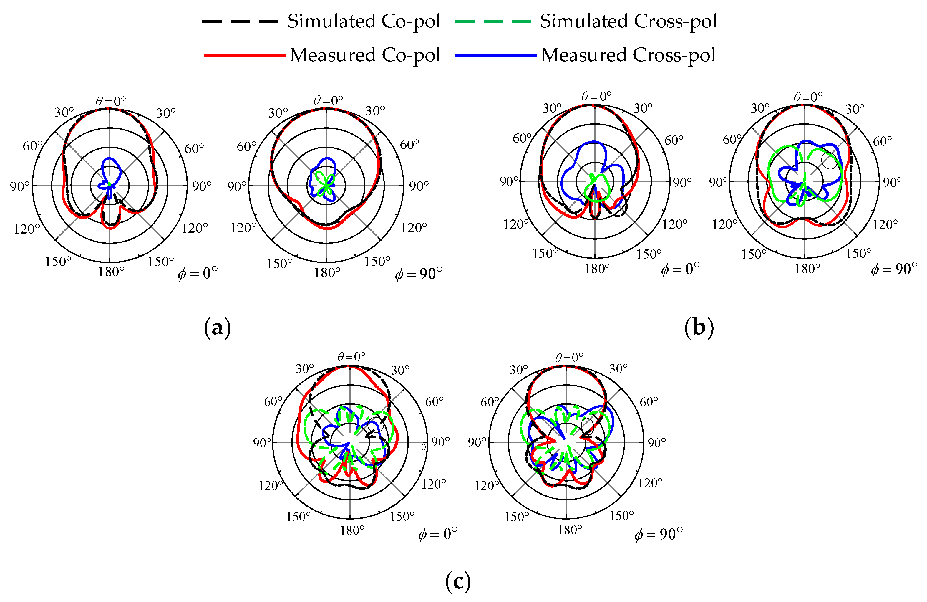
After assembling the antenna and the feeding network, the simulated and measured S-parameters and realized gain are plotted in Figure 12. As shown, the measured −10 dB impedance bandwidth is from 2.10 GHz to 3.95 GHz indicating 61% fractional bandwidth. The measured isolation is below 25 dB, which guarantees enough isolation between the two polarizations. The simulated and measured realized gains are shown in Figure 12b after respectively stimulating port 1 or port 2. When port 1 is excited, the measured realized gain varies from 6.23 dBi to 8.39 dBi with an average gain of 7.31 dBi. When port 2 is stimulated, it varies from 6.25 dBi to 8.35 dBi. Due to the fabrication, manual welding, and other errors, the measured gain is about 1 dB lower than the simulation. However, wide bandwidth, stable gain, and consistent radiation patterns are proved. The measured, normalized radiation patterns at the frequencies of 2.15 GHz, 2.9 GHz, and 3.85 GHz are shown in Figure 13. In all the frequencies, the measured co-polarization shows the agreement with the simulated ones, and the cross-polarization is less than −19 dB. The measured back to front radio is lower than −17 dB. It can be observed that the radiation keeps a consistent unidirectional beam. The measured radiation efficiencies are 75%, 62.6% and 55.7% at 2.15 GHz, 2.9 GHz, and 3.85 GHz, respectively.
To present the bandwidth and profile of the proposed antenna, a comprehensive comparison with other antennas is presented in Table 2. Patch antennas are designed in [4,9] and dipole antennas are designed in [17,21,22,33]. The profiles in [4,9] are higher and the bandwidths are at the same level as that of the proposed antenna. The antennas in [17,21,22] have tinnier areas than the proposed antenna, but the bandwidth is narrower by 9%, 6%, and 28%. Though the height in [33] is approximate to this work, the proposed antenna has a broader bandwidth. Therefore, by utilizing multi-mode patch arms and coupling feed, the proposed design shows a wider bandwidth within the low profile.
4. Conclusions
A low-profile, wideband, dual-polarized patch antenna has been proposed in this communication. The arrow-shaped arms are specially designed to excite three modes simultaneously. Shorting pins have been introduced at the wings of the arrows to obtain stable radiation patterns. Moreover, the coupling feeds are utilized for wideband impedance matching without the increase of height. Two pairs of the differentially fed arrow-shaped arms are arranged orthogonally to realize dual polarization. The antenna prototype has achieved 61% bandwidth, an average gain of 7.31 dBi, and a 0.1λ0 profile. Additionally, the isolation of the dual-polarized antenna has been below 25 dB. With the attractive features of a low profile, wide bandwidth and stable radiation patterns, the proposed antenna would be a strong candidate for future wireless communication.
Author Contributions
Conceptualization, Y.L., L.W. and K.W.; methodology, H.C. and Z.C.; software, Z.C.; validation, Y.L. and K.W.; formal analysis, K.W.; investigation, K.W.; resources, L.W.; data curation, L.W.; writing—original draft preparation, Y.L., K.W. and Z.C.; writing—review and editing, H.C.; visualization, Z.C. and K.W.; supervision, Y.L.; project administration Z.C. and K.W. All authors have read and agreed to the published version of the manuscript.
Funding
This work was supported in part by the National Key Research and Development Program of China (No. 2020YFB1807300), the National Natural Science Foundation of China under Grand 62001140, the Shenzhen Basic Research Program under Grant GXWD20201230155427003-20200824201212001, the Open Research Project of Guangdong Provincial Key Laboratory of Millimeter-Wave and Terahertz (No. 2019B030301002KF2002), the Shenzhen Science and Technology Program under Grant KQTD20210811090116029, the Major Key Project of PCL (PCL2021A03-1), the Shenzhen Science and Technology Program ZDSYS20210623091808025 and the National Natural Science Foundation of China under Grant 61901139.
Data Availability Statement
The data presented in this study are available on request from the corresponding author.
Conflicts of Interest
The authors declare no conflict of interest.
References
- Luo, Y.; Chen, Z.N.; Ma, K. A single-layer dual-polarized differentially fed patch antenna with enhanced gain and bandwidth operating at dual compressed high-order modes using characteristic mode analysis. IEEE Trans. Antennas Propag. 2020, 68, 4082–4087. [Google Scholar] [CrossRef]
- Liu, N.; Zhu, L.; Choi, W. A differential-fed microstrip patch antenna with bandwidth enhancement under operation of TM10 and TM30 modes. IEEE Trans. Antennas Propag. 2017, 65, 1607–1614. [Google Scholar] [CrossRef]
- Saxena, S.; Kanaujia, B.K.; Dwari, S.; Kumar, S.; Tiwari, R. A Compact Dual Polarized MIMO Antenna with Distinct Diversity Performance for UWB Applications. IEEE Antennas Wirel. Propag. Lett. 2017, 16, 3096–3099. [Google Scholar] [CrossRef]
- Mak, K.M.; Lai, H.W.; Luk, K.M. A 5G wideband patch antenna with antisymmetric L-shaped probe feeds. IEEE Trans. Antennas Propag. 2018, 66, 957–961. [Google Scholar] [CrossRef]
- Wong, H.; Lau, K.-L.; Luk, K.-M. Design of dual-polarized L-probe patch antenna arrays with high isolation. IEEE Trans. Antennas Propag. 2014, 52, 45–52. [Google Scholar] [CrossRef]
- Ryu, K.S.; Kishk, A.A. Wideband dual-polarized microstrip patch excited by hook shaped probes. IEEE Trans. Antennas Propag. 2008, 56, 3645–3649. [Google Scholar] [CrossRef]
- Ghorbani, K.; Waterhouse, R.B. Dual polarized wide-band aperture stacked patch antennas. IEEE Trans. Antennas Propag. 2004, 52, 2171–2175. [Google Scholar] [CrossRef]
- Barba, M. A high-isolation, wideband and dual-linear polarization patch antenna. IEEE Trans. Antennas Propag. 2008, 56, 1472–1476. [Google Scholar] [CrossRef] [Green Version]
- Tang, Z.; Liu, J.; Cai, Y.-M.; Wang, J.; Yin, Y. A wideband differentially fed dual-polarized stacked patch antenna with tunedslot excitations. IEEE Trans. Antennas Propag. 2018, 66, 2055–2060. [Google Scholar] [CrossRef]
- Radavaram, S.; Pour, M. A wideband coplanar L-strip fed rectangular patch antenna. IEEE Antennas Wireless Propag. Lett. 2021, 20, 1779–1783. [Google Scholar] [CrossRef]
- Deng, C.; Li, Y.; Zhang, Z.; Feng, Z. A wideband high-isolated dual-polarized patch antenna using two different Balun feedings. IEEE Antennas Wireless Propag. Lett. 2014, 13, 1617–1619. [Google Scholar] [CrossRef]
- Zhang, K.; Zhu, F.; Gao, S. Differential-fed ultra-wideband slot loaded patch antenna with dual orthogonal polarization. Electron. Lett. 2013, 49, 1591–1593. [Google Scholar] [CrossRef]
- Sun, D.; Zhang, Z.; Yan, X.; Jiang, X. Design of broadband dual polarized patch antenna with backed square annular cavity. IEEE Trans. Antennas Propag. 2016, 64, 43–52. [Google Scholar] [CrossRef]
- White, C.R.; Rebeiz, G.M. A differential dual-polarized cavity backed microstrip patch antenna with independent frequency tuning. IEEE Trans. Antennas Propag. 2010, 58, 3490–3498. [Google Scholar] [CrossRef]
- Nawaz, H.; Tekin, I. Double-differential-fed, dual-polarized patch antenna with 90 dB interport RF isolation for a 2.4 GHz in-band full duplex transceiver. IEEE Antennas Wireless Propag. Lett. 2018, 17, 287–290. [Google Scholar] [CrossRef]
- Nawaz, H.; Tekin, I. Dual-polarized, differential fed microstrip patch antennas with very high interport isolation for full-duplex communication. IEEE Trans. Antennas Propag. 2017, 65, 7355–7360. [Google Scholar] [CrossRef]
- Wen, D.; Zheng, D.; Chu, Q. A wideband differentially fed dual-polarized antenna with stable radiation pattern for base stations. IEEE Trans. Antennas Propag. 2017, 65, 2248–2255. [Google Scholar] [CrossRef]
- Chu, Q.; Wen, D.; Luo, Y. A broadband ±45° dual-polarized antenna with Y-shaped feeding lines. IEEE Trans. Antennas Propag. 2015, 63, 483–490. [Google Scholar] [CrossRef]
- Yang, W.; Pan, Y. A wideband dual-polarized dipole antenna with folded metallic plates. IEEE Antennas Wireless Propag. Lett. 2018, 17, 1797–1801. [Google Scholar] [CrossRef]
- Wang, B.; Liao, C.; Du, C.-H. A low-profile broadband dual-polarized base station antenna array with well-suppressed cross-polarization. IEEE Trans. Antennas Propag. 2021, 69, 8354–8365. [Google Scholar] [CrossRef]
- Li, M.; Li, Q.L.; Wang, B.; Zhou, C.F.; Cheung, S.W. A low-profile dual-polarized dipole antenna using wideband AMC reflector. IEEE Trans. Antennas Propag. 2018, 66, 2610–2615. [Google Scholar] [CrossRef]
- Zhu, H.; Qiu, Y.; Wei, G. A broadband dual-polarized antenna with low profile using nonuniform metasurface. IEEE Antennas Wireless Propag. Lett. 2019, 18, 1134–1138. [Google Scholar] [CrossRef]
- Xue, Q.; Liao, S.W.; Xu, J.H. A differentially-driven dual polarized magneto-electric dipole antenna. IEEE Trans. Antennas Propag. 2013, 61, 425–430. [Google Scholar] [CrossRef]
- Luo, Y.; Chu, Q.-X. Oriental crown-shaped differentially fed dualpolarized multidipole antenna. IEEE Trans. Antennas Propag. 2015, 63, 4678–4685. [Google Scholar] [CrossRef]
- Cui, Y.; Gao, X.; Li, R. A broadband differentially fed dual polarized planar Antenna. IEEE Trans. Antennas Propag. 2017, 65, 3231–3234. [Google Scholar] [CrossRef]
- Tang, Z.; Liu, J.; Yin, Y. Enhanced cross-polarization discrimination of wideband differentially fed dual-polarized antenna via a shorting loop. IEEE Antennas Wireless Propag. Lett. 2018, 17, 1454–1458. [Google Scholar] [CrossRef]
- Tang, Z.; Liu, J.; Lian, R.; Li, Y.; Yin, Y. Wideband differentially fed dual-polarized planar antenna and its array with high common mode suppression. IEEE Trans. Antennas Propag. 2019, 67, 131–139. [Google Scholar] [CrossRef]
- Ma, Z.L.; Chan, C.H. Waveguide-based differentially fed dual polarized magnetoelectric dipole antennas. IEEE Trans. Antennas Propag. 2017, 65, 3849–3857. [Google Scholar] [CrossRef]
- Zhang, Y.P.; Wang, J.J. Theory and analysis of differentially-driven microstrip antennas. IEEE Trans. Antennas Propag. 2006, 54, 1092–1099. [Google Scholar] [CrossRef]
- Kumar, G.; Ray, K.P. Broadband Microstrip Antennas; Artech: Norwood, MA, USA, 2002. [Google Scholar]
- Eisenstadt, W.R.; Stengel, B.; Thompson, B.M. Microwave Differential Circuit Design Using Mixed-Mode S-Parameters; Artech House: Boston, MA, USA, 2006. [Google Scholar]
- Zhang, Z.-Y.; Guo, Y.-X.; Ong, L.C.; Chia, M.Y.W. A new wide-band planar balun on a single-layer PCB. IEEE Microw. Wireless Compon. Lett. 2005, 15, 416–418. [Google Scholar] [CrossRef]
- Xiong, H.Q.; Zhang, C.J.; Tong, M.S. Wideband low-profile dual-polarized antenna based on a gain-enhanced EBG reflector. IEEE Trans. Antennas Propag. 2022, 12, 391–394. [Google Scholar] [CrossRef]
Figure 1.
Configuration of the proposed antenna.
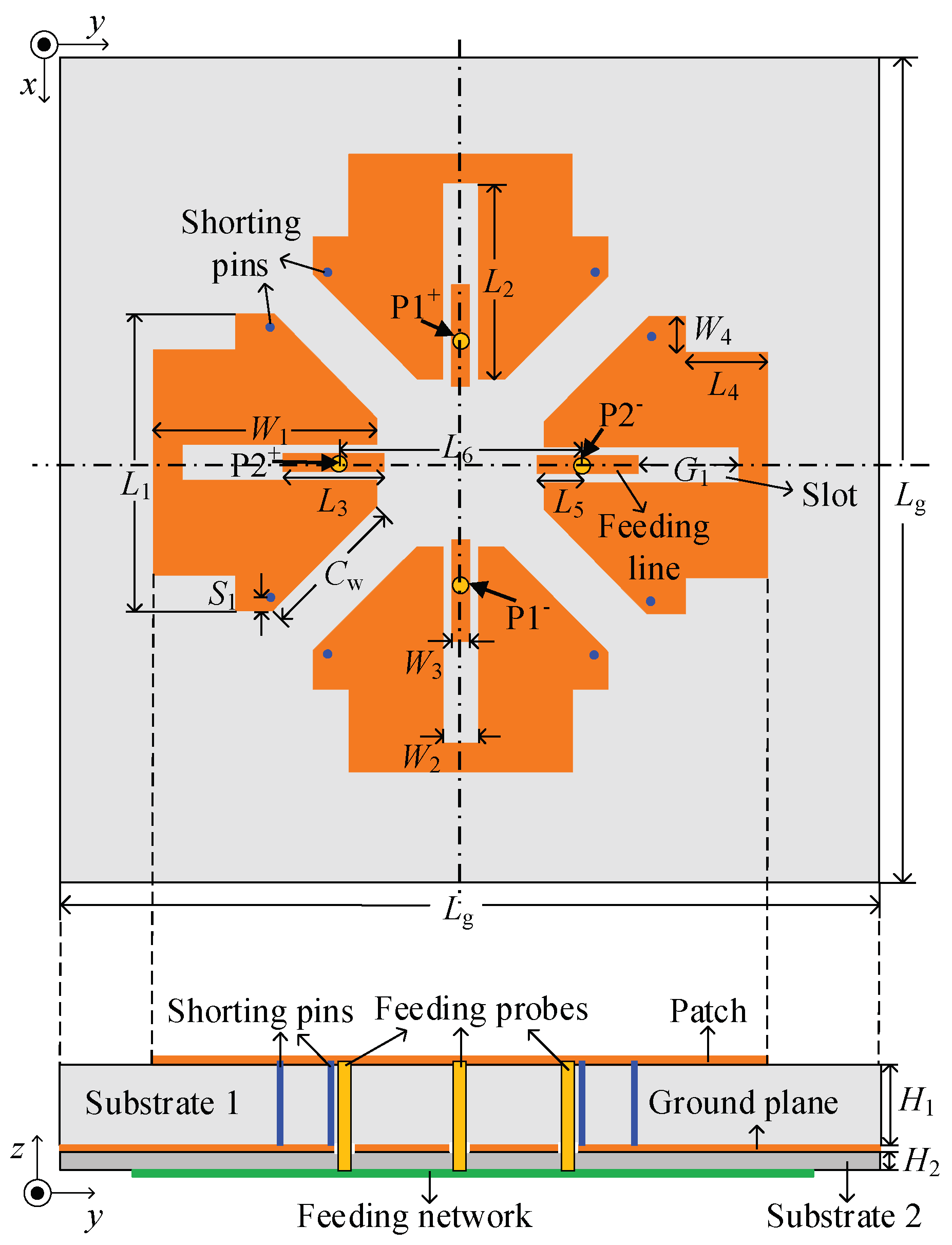
Figure 2.
The evolution of the proposed antenna arm. The configuration of (a) arm I, (b) arm II, (c) arm III and (d) arm IV.
Figure 2.
The evolution of the proposed antenna arm. The configuration of (a) arm I, (b) arm II, (c) arm III and (d) arm IV.
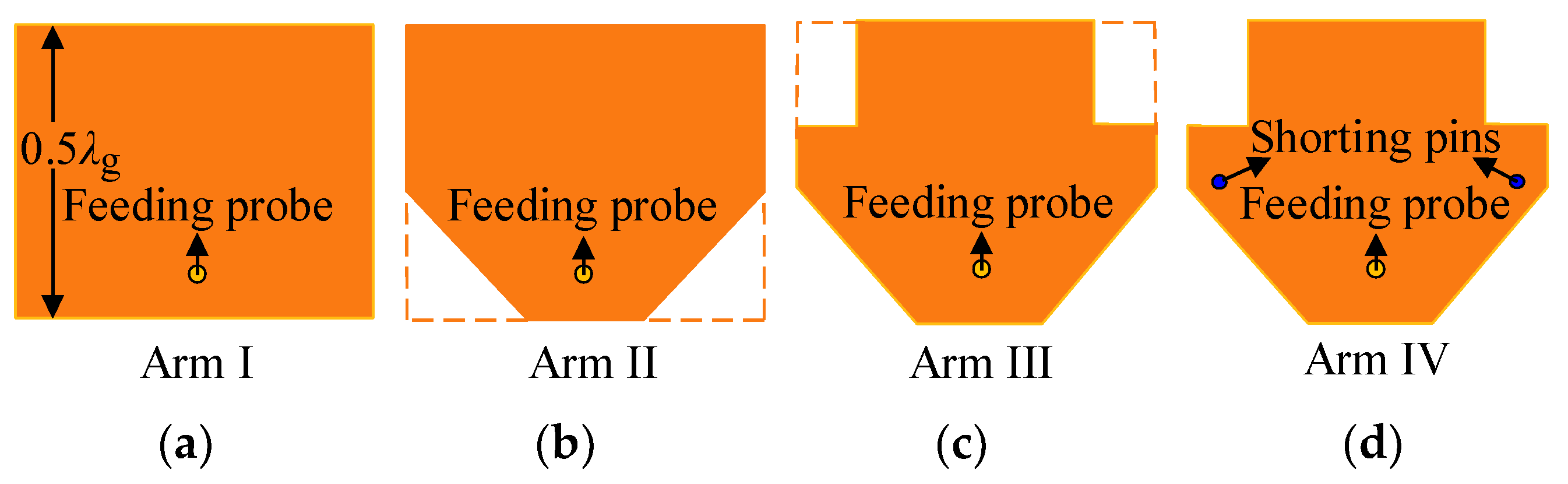
Figure 3.
Current distributions on Arm II (a) Mode 1. (b) Mode 2. (c) Mode 3. The color scale represents the magnitude of surface current distribution (A/m) and the arrows indicate the current phase.
Figure 3.
Current distributions on Arm II (a) Mode 1. (b) Mode 2. (c) Mode 3. The color scale represents the magnitude of surface current distribution (A/m) and the arrows indicate the current phase.

Figure 4.
Configuration and simulated results. (a) Antenna I and Antenna II. (b) Differential input impedances.
Figure 4.
Configuration and simulated results. (a) Antenna I and Antenna II. (b) Differential input impedances.
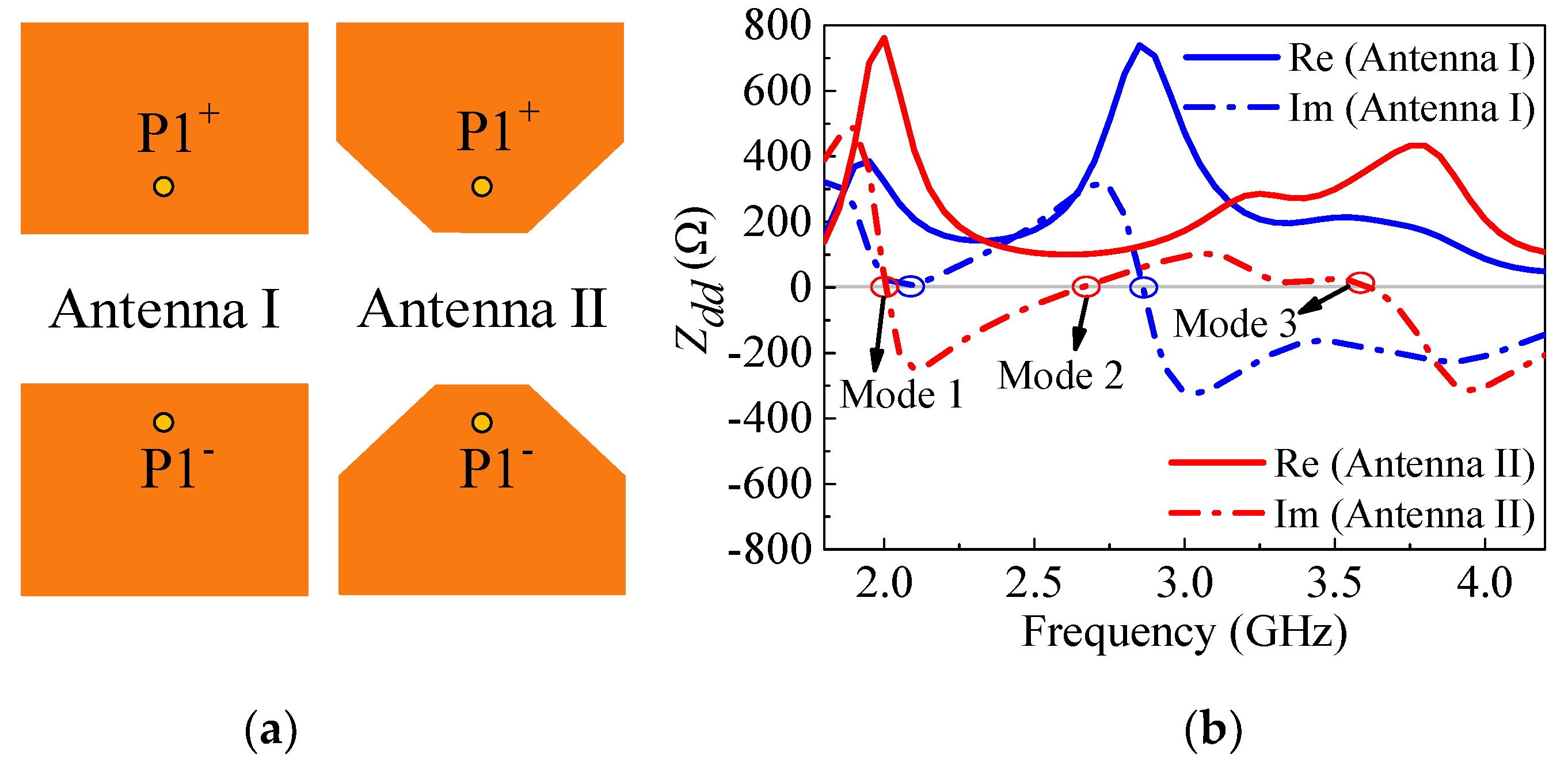
Figure 5.
(a) Current distribution of Mode 3 on Arm III. (b) Resonant frequencies of the three modes versus W4. The color scale represents the magnitude of surface current distribution (A/m) and the arrows indicate the current phase.
Figure 5.
(a) Current distribution of Mode 3 on Arm III. (b) Resonant frequencies of the three modes versus W4. The color scale represents the magnitude of surface current distribution (A/m) and the arrows indicate the current phase.
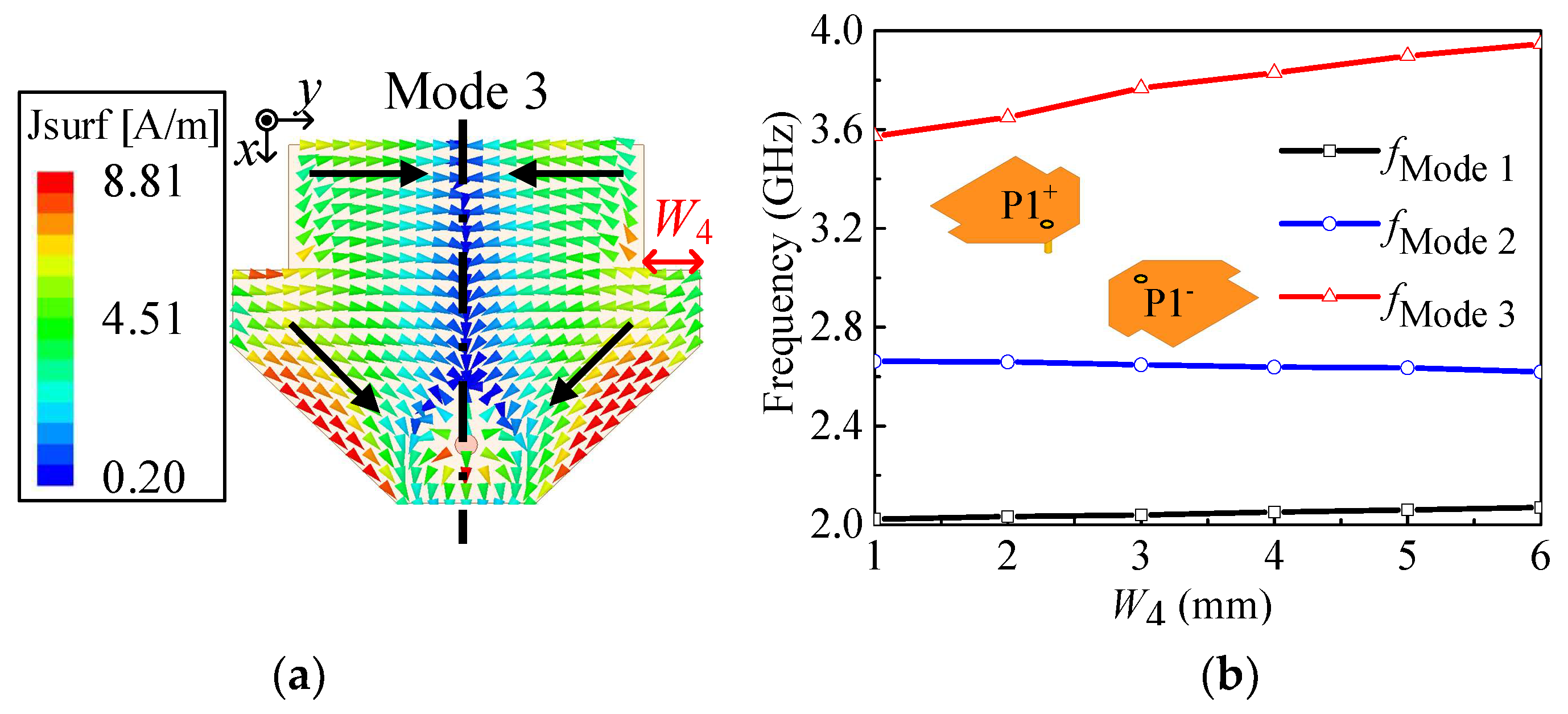
Figure 6.
(a) Current distributions. (b) 3-D radiation patterns of the three modes. The color scale represents the magnitude of surface current distribution (A/m) and the arrows indicate the current phase.
Figure 6.
(a) Current distributions. (b) 3-D radiation patterns of the three modes. The color scale represents the magnitude of surface current distribution (A/m) and the arrows indicate the current phase.
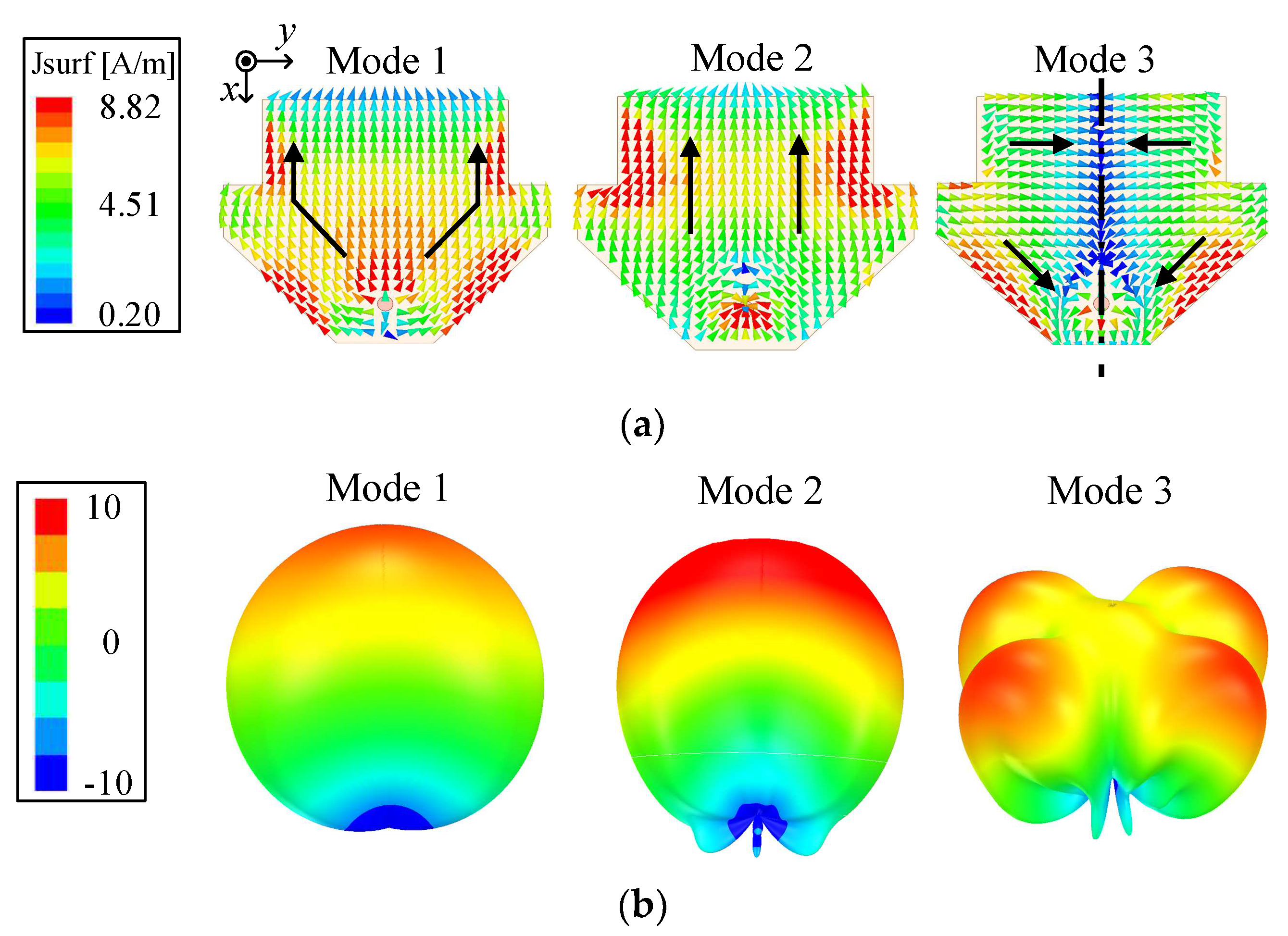
Figure 7.
Electric field distributions of the three modes.

Figure 8.
(a) Current distributions. (b) Radiation patterns with shorting pins (Arm IV). The color scale represents the magnitude of surface current distribution (A/m) and the arrows indicate the current phase.
Figure 8.
(a) Current distributions. (b) Radiation patterns with shorting pins (Arm IV). The color scale represents the magnitude of surface current distribution (A/m) and the arrows indicate the current phase.

Figure 9.
Simulated results. (a) Input impedances. (b) Reflection coefficients.
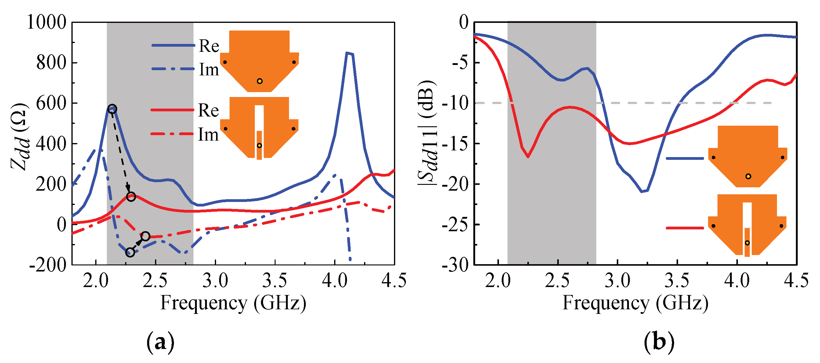
Figure 10.
Configuration of the feeding network.
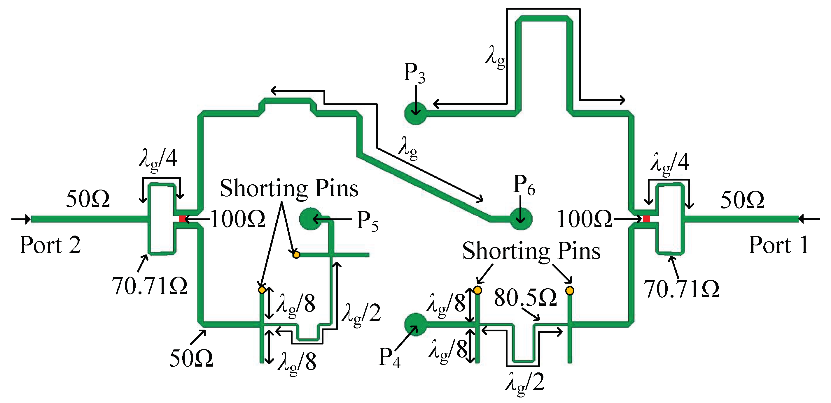
Figure 11.
Fabricated prototype. (a) Proposed antenna. (b) Feeding network. (c) Under test in the Satimo Starlab System.
Figure 11.
Fabricated prototype. (a) Proposed antenna. (b) Feeding network. (c) Under test in the Satimo Starlab System.
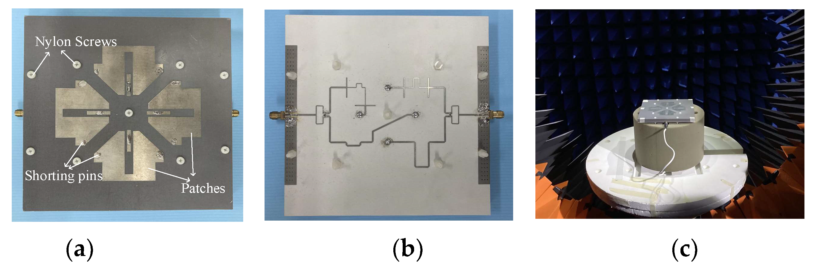
Figure 12.
Simulated and measured results. (a) S-parameters. (b) Realized gain.
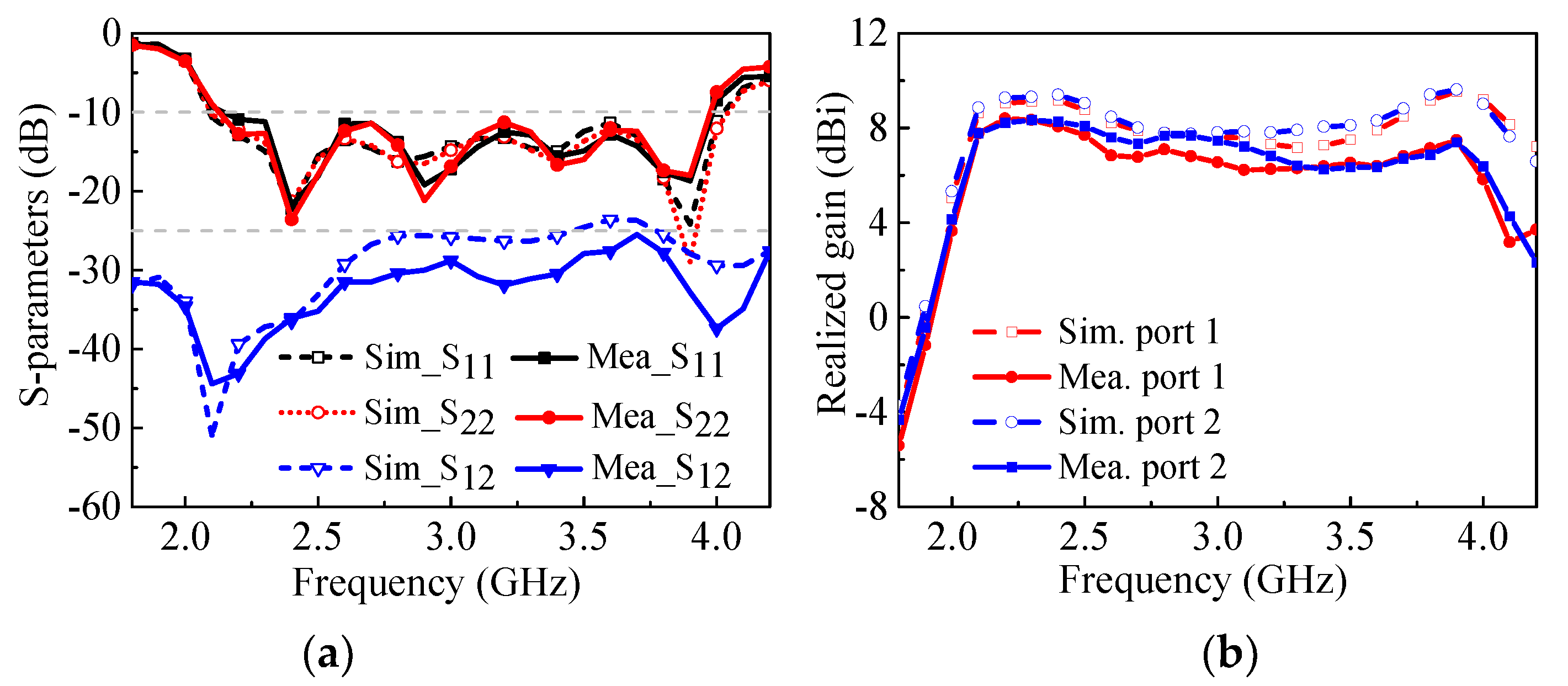
Figure 13.
Simulated and measured radiation patterns. (a) 2.15 GHz. (b) 2.9 GHz. (c) 3.85 GHz.

Table 1.
Dimensions of the proposed antenna.
| Parameters | Lg | L1 | W1 | L2 | W2 | L3 | W3 | L4 |
| Value (mm) | 149 | 50 | 38 | 33 | 6 | 17 | 3 | 14 |
| Parameters | L4 | W4 | Cw | L5 | L6 | G1 | H1 | H2 |
| Value (mm) | 14 | 6 | 17.5 | 6.5 | 41 | 17 | 10 | 0.508 |
Table 2.
Comprehensive comparsion with other antennas.
| Ref. | Bandwidth | Profile (λ0) 1 | Size (λ02) | Isolation (dB) | Gain (dBi) | Type |
|---|---|---|---|---|---|---|
| [4] | 54% (VSWR < 2) | 0.23 | 0.38 × 0.38 | >30 | 7.4 | Patch |
| [9] | 57% (|S11| < −10) | 0.27 | 0.55 × 0.55 | >37 | 8.7 | Patch |
| [17] | 52% (VSWR < 1.5) | 0.26 | 0.58 × 0.58 | >26 | 8.5 | Dipole |
| [21] | 54.8% (|S11| < −10) | 0.13 | 0.78 × 0.78 | >20 | 7.3 | Dipole |
| [22] | 33% (|S11| < −10) | 0.1 | 0.48 × 0.48 | >25 | 8.3 | Dipole |
| [33] | 42.9% (|S11| < −10) | 0.08 | 1.03 × 1.03 | >25 | 9.89 | Dipole |
| This Work | 61% (|S11| < −10) | 0.1 | 1.05 × 1.05 | >25 | 7.31 | Patch |
1 λ0: wavelength of free space at the center frequency.
Disclaimer/Publisher’s Note: The statements, opinions and data contained in all publications are solely those of the individual author(s) and contributor(s) and not of MDPI and/or the editor(s). MDPI and/or the editor(s) disclaim responsibility for any injury to people or property resulting from any ideas, methods, instructions or products referred to in the content. |
© 2023 by the authors. Licensee MDPI, Basel, Switzerland. This article is an open access article distributed under the terms and conditions of the Creative Commons Attribution (CC BY) license (https://creativecommons.org/licenses/by/4.0/).
Share and Cite
MDPI and ACS Style
Li, Y.; Wei, L.; Wang, K.; Cai, H.; Chen, Z. Low-Profile Wideband Dual-Polarized Patch Antenna Based on Differential-Paired Multi-Mode Arms. Electronics 2023, 12, 2604. https://doi.org/10.3390/electronics12122604
AMA Style
Li Y, Wei L, Wang K, Cai H, Chen Z. Low-Profile Wideband Dual-Polarized Patch Antenna Based on Differential-Paired Multi-Mode Arms. Electronics. 2023; 12(12):2604. https://doi.org/10.3390/electronics12122604
Chicago/Turabian StyleLi, Yuanchun, Lijuan Wei, Kaixu Wang, Hanzhen Cai, and Zihao Chen. 2023. "Low-Profile Wideband Dual-Polarized Patch Antenna Based on Differential-Paired Multi-Mode Arms" Electronics 12, no. 12: 2604. https://doi.org/10.3390/electronics12122604
Note that from the first issue of 2016, this journal uses article numbers instead of page numbers. See further details here.