Article

Optical Frequency Comb Generator Employing Two Cascaded Frequency Modulators and Mach–Zehnder Modulator

1
Department of Computer Science and Engineering, Manipal Institute of Technology, Manipal Academy of Higher Education, Manipal 576104, Karnataka, India
2
School of Electronics Engineering, Vellore Institute of Technology, Vellore 632014, Tamil Nadu, India
*
Author to whom correspondence should be addressed.
Electronics 2023, 12(13), 2762; https://doi.org/10.3390/electronics12132762
Submission received: 20 May 2023 / Revised: 18 June 2023 / Accepted: 19 June 2023 / Published: 21 June 2023
(This article belongs to the Special Issue Optical Fiber and Optical Communication)

Abstract

:
Optical frequency combs (OFCs) are extensively used in spectroscopy, range finding, metrology, and optical communications. In this paper, we propose a novel technique to achieve a flat OFC by serially cascading two frequency modulators (FMs) followed by a single-drive Mach–Zehnder modulator (MZM). The modulators are driven by a sinusoidal RF signal of frequencies f m , f m 2 , and 2 f m GHz, respectively. With our proposed approach ( f m ), an optical spectrum of 71 subcarriers spaced at 4 GHz is realized within a power fluctuation of ∼2 dB. The proposed method is also tested for f m = 16 GHz, showing that this approach can work in all scenarios with lower power fluctuations. In addition, we also studied the impact of the phase of the RF signal on the power variation of the OFC spectrum. A theoretical investigation of the ultra-flat spectrum generated by cascaded FMs and MZM is conducted, and the results of simulations support the findings. The simulation results demonstrate good performance, allowing for the application of our proposed approach in next-generation optical networks.

1. Introduction

An optical frequency comb (OFC) is an optical spectrum comprising a group of evenly spaced frequency lines with a stable and coherent phase relationship [1,2]. OFCs have drawn excellent research interest due to their wide range of applications, including radio frequency (RF) photonics [3], metrology [4], optical communications [5], radio over fiber, spectroscopy [6], terahertz wireless technologies [7], and arbitrary waveform generation [8].
Several techniques have been proposed for generating OFCs, viz., mode-locked lasers (MLLs) [9], optical microresonators [10], and electro-optic modulators [11]. The MLL is a conventional approach for generating ultrashort pulses by controlling cavity parameters [12]. Here, spectral lines are arranged close together, which reduces line spacing and weakens the stability of the spectrum. Furthermore, the longer laser cavity in the MLL limits comb lines to a range of a few MHz to 1 GHz [13], although the spacing between the lines can be expanded by optical filters [14]. However, the dependence of the MLL on the laser cavity results in poor flexibility and tunability. In addition, exact phase locking is required by the MLL for the generation of an OFC, making the system incompatible with various applications in communication. The optical microresonator approach has an integrated structure. It can produce an OFC with a large number of subcarriers, but its design is more complicated, and it is very difficult to adjust the spectral interval. In contrast, the OFC generated using electro-optic modulators is preferred over that produced by MLL for wavelength division multiplexing (WDM) due to its clearly defined frequency spacing and freely tunable center wavelength. However, the OFC produced with a single electro-optic modulator exhibits more severe power fluctuations. The intensity modulator (IM) can be connected to a single- or multiple-phase modulator in cascaded mode to resolve this problem.
Recently, considerable development has been made in generating OFCs based on modulators. The authors of ref. [15] generated an OFC using conventional dual-drive Mach–Zehnder modulators (DD-MZM) powered by strong sine wave signals. This approach can generate 11 comb lines and 19 comb lines within a power deviation of 1.1 dB and 4.3 dB, respectively. In ref. [16], an OFC is generated using a single-phase modulator (PM) driven by dual sine waves with distinct amplitudes and frequencies. This proposed approach can generate an 11-line OFC with 3 GHz spacing and within 1.9 dB power fluctuation. It can also generate a 9-line OFC within 0.8 dB power fluctuation. The generated comb provides a small bandwidth with good power efficiency, making it suitable for line-by-line shaping systems, microwave photonics, and optical filter testing. In ref. [17], an OFC generator is proposed that uses a single DD-MZM driven at one arm with a sinusoidal RF signal, and at another arm with twice the frequency. Using this approach, nine, five, four, and three comb lines are generated with 1.2 dB spectral flatness.
By serially cascading two PMs and inserting a dispersion medium (fiber Bragg grating (FBG)) between these modulators, the authors of ref. [18] generated an OFC. The output spectrum contains 61 comb lines spaced at 25 GHz and within a power fluctuation of 8 dB. In ref. [19], the generation of a flat OFC by cascading IM and PM driven by tailored RF waveforms is proposed. The output spectrum contains 38 comb lines spaced at 10 GHz and within 1 dB of power fluctuation, and 60 comb lines overall. In ref. [20], the authors generated an OFC by connecting IM and PM modulators in cascaded mode and driven by a sinusoidal waveform without using a chirped FBG or specially tailored RF waveforms. This approach produces a 15-line OFC with a power deviation of 1 dB. In addition, in ref. [21], they also generated a 29-line OFC with 10 GHz spacing and within 1.5 dB power deviation by cascading one IM and two PMs.
In ref. [22], five and seven comb lines within 0.1 dB and 1 dB power deviation are generated using an independent dual-parallel MZM driven by a sinusoidal RF signal. The authors of ref. [23] used an electroabsorption modulator (EAM) and two cascaded PMs to generate an OFC. Using this approach, 11 comb lines spaced at 40 GHz are generated with a power fluctuation of 3 dB. In this work, the EAM performs amplitude gating, and has a shorter time window than the MZM. The generation of an OFC based on the chirping of modulators was demonstrated in [24]. This method has two serially cascaded MZM modulators, the first of which is driven immediately by a sinusoidal RF signal, and the latter one is driven after a delay. This delay in time between the driving RF signals decreases the power deviation in the output spectrum. The output spectrum contains 27 comb lines within 1 dB power fluctuation and 51 comb lines in total. A completely digital programmable OFC generation technique is proposed in [25]. Here, bit sequence programming allows the tuning of both the comb line spacing and comb line count, and 19, 39, 61, 81, 101, or 201 comb lines spaced at 100, 50, 20, 10, 5, or 1 MHz are achieved by digital programming. In ref. [26], a flexible on-chip OFC generation approach has been demonstrated using two cascaded MZMs in silicon photonics. This proposed approach generates nine comb lines with 10 GHz spacing and with a power deviation of 6.5 dB. The authors of ref. [27] generated an OFC by the cascading of a PM and DD-MZM. This method generated 60 comb lines with power deviations ranging from 0 to 6 dB. The authors of ref. [28] presented the generation of a flat OFC based on dual-parallel MZM and superposed harmonics, where the superposed harmonics drive just one MZM of a dual-parallel MZM. Here, driving the dual-parallel MZM with the fundamental tone and third harmonic in superposition results in 9 comb lines within a power fluctuation of 0.26 dB, and driving the dual-parallel MZM concurrently with the fundamental tone, second harmonic, and third harmonic results in 13 comb lines within a power fluctuation of 0.58 dB. In ref. [29], an OFC based on serial cascading of two single-drive MZMs is proposed. Using this approach, five comb lines spaced at 10 GHz are generated within a power fluctuation of 0.77 dB. In ref. [30], an OFC is generated by connecting an MZM and EAM in cascaded mode with a Gaussian-shaped pulse signal. This method generates a 35-line OFC with a power deviation of 2.14 dB. Moreover, the OFC’s frequency spacing can be adjusted from 1 to 10 GHz. In ref. [31], an OFC generator is presented that uses serial cascading of two IMs and one PM. With this method, 24 spectral lines within a power deviation of 1.1 dB are produced.
A silicon ring resonator modulator was used by the authors of ref. [32] to generate a coherent OFC in the C-band that had five comb lines spaced at 10 GHz. The electrical input could be tuned appropriately, allowing the comb shape to be customized and keeping the power deviation between the lines within 0.7 dB. The authors of ref. [33] generated an OFC in an integrated lithium niobate ultrahigh-Q microresonator. The OFC operates in the telecom L-band and has over 250 comb lines spaced 25 GHz apart. A novel technique for generating an OFC in an optoelectronic oscillator is proposed in ref. [34]. This method allows one to tune the comb characteristics by adjusting the modulating signal amplitudes and frequencies sent to the Mach–Zehnder modulator’s arms. The optoelectronic oscillator loop’s delay line and microresonator characteristics were investigated using numerical modeling. The authors of ref. [35] demonstrated an OFC with five comb lines spaced apart at 10 GHz and power fluctuation within 0.86 dB using a silicon microring modulator and a microring resonator filter.
In ref. [36], a novel method for generating flat OFCs based on a digital signal-driven intensity modulator and band-stop optical filter is proposed. Compared to earlier techniques based on radio-frequency-driven IMs, this approach is more adaptable and less complex. The generated OFC possesses properties such as a large number of comb lines within 0.4 dB power fluctuation, a customizable number of comb lines using a band-pass filter, and adjustable comb spacing. The authors of ref. [37] generated a flat OFC using cascading PMs with combined harmonics. For the scenario of a combined fundamental tone, third harmonic, and fifth harmonic, a 15-line OFC is generated, with the flatness measured in simulation and experiment to be 0.29 dB and 0.65 dB, respectively. The authors of ref. [38] proposed an OFC using a PM and Gaussian band-stop filter. By adjusting the square wave signal’s period and the bandwidth of the Gaussian band-stop filter, the OFC’s flatness and the spacing between the comb lines can be altered. The simulation results demonstrate the generation of hundreds of comb lines within 0.5 dB power variation.
In this work, we have generated an ultra-flat and wide-band OFC by the serial cascading of two frequency modulators (FMs) followed by a single-drive MZM. Here, the FMs are driven by a sinusoidal RF signal of frequencies f m and f m 2 , respectively, while the MZM is driven by a sinusoidal RF signal of frequency 2 f m . The first FM generates the subcarriers, while the second FM enhances the number of subcarriers. However, subcarriers at the output of the second FM have a power variation of around 30 dB. Thus, the output of the second FM is fed into a single-drive MZM that works as an intensity modulator. The nonlinear effect of the intensity modulator improves the flatness of the OFC by exciting the weak sidebands. We also studied the impact of the phase of the RF signal on the power variation of the OFC spectrum. The optical spectrum of 71 and 38 subcarriers is achieved using our proposed method with frequency spacing of 4 GHz and 8 GHz, respectively, and within a power fluctuation of ∼2 dB.

2. Principle of Operation

Figure 1 illustrates the schematic diagram of the OFC generation. Here, we cascade a laser source with two FMs and a single-drive MZM. The modulators are driven by sinusoidal RF signals with frequencies of f m , f m /2, and 2 f m , respectively. Here, RF signals drive the modulators directly, eliminating the need for a phase shifter or amplifier. This results in a simple, stable, and power-efficient design.
The specifications for all devices are described as follows: the power, linewidth, and center frequency of the laser are 1 mW, 10 MHz, and 193.1 THz, respectively; the frequency deviation of both FMs is 10 GHz; the bias voltage 1, bias voltage 2, and modulation voltage of the MZM are −2.8 V, −1.1 V, and 15 V, respectively; The amplitude and phase of RF1, RF2, and RF3 are 2 a.u. and 90 degrees, 2 a.u. and 45 degrees, and 2 a.u. and 90 degrees, respectively. Our proposed approach is tested for two sets of RF1, RF2, and RF3 signals: 16 GHz, 8 GHz, and 32 GHz and 8 GHz, 4 GHz and 16 GHz, respectively.
This proposed approach can also be used with other sets of RF signal frequencies, but the power deviation is minimal at f m = 8 GHz and 16 GHz. To examine the spectrum, the output signal is fed into an optical spectrum analyzer (OSA) with a resolution of 0.01 nm.
The system comprises three sections: a continuous wave (CW) laser source, a sinusoidal RF signal, and modulators. The first wavelength and the initial frequency of the generated OFC are provided by the laser source. The frequency of the RF signal is associated with the frequency separation between the comb lines. Whenever the signal traverses through the modulator, its frequency is shifted as per the RF signal’s frequency, and the CW laser occupies the free space. Consequently, a large number of frequency components are produced, which eventually result in an OFC.
We connected two FMs and an MZM in cascading mode to generate an OFC. The first FM generates the subcarriers, while the second FM increases the number of subcarriers. However, the subcarriers generated at the output of cascaded FMs have poor spectral flatness. Thus, they are further cascaded with the MZM to produce a flattened spectrum at the output by equalizing the power deviation of both the even and odd sidebands.
MZM is an electro-optic modulator where the change in the applied electric field leads to a variation in the refractive index in the modulator arms. It is made up of two waveguides that serve as arms of the interferometer. The laser is connected to an input waveguide, which in turn is divided into two paths, each of which has electrodes surrounding it. These electrodes are connected to the modulated signal voltage and DC bias voltage, which change the refractive index of each arm, resulting in phase modulation due to the shift in the refractive index. The phase modulation is finally translated to intensity modulation by joining the arms of the interferometer. The nonlinear impact of the intensity modulator flattens the spectrum at the MZM output by tuning the power deviation of sidebands. Here, we employ an MZM with a single drive, where both arms receive the same modulation voltage. The optical input branch of the MZM receives the output of the second FM, and the RF signal with frequency 2 f m drives the electrical input branch.

3. Results and Discussion

To confirm the operating principle, we perform a theoretical analysis and discussion of the cascaded FMs and MZM. The cascaded FMs and MZM are driven by sinusoidal RF signals with frequencies f 1 = f m GHz, f 2 = f m /2 GHz, and f 3 = 2 f m GHz. In addition, we also analyzed the optical spectrum by driving the modulators with a sinusoidal RF signal at frequencies f 1 = f m GHz, f 2 = f m GHz, and f 3 = 2 f m GHz. The simulation result of our proposed approach for generating OFCs was obtained using the commercial software Optiwave (Optisystem version 19). To validate the proposed approach’s efficiency, RF signals have been supplied to the FM1, FM2, and MZM with two sets of frequencies: 16 GHz, 8 GHz, and 32 GHz and 8 GHz, 4 GHz, and 16 GHz, respectively. It is noticeable that modulators driving with 8 GHz, 4 GHz, and 16 GHz frequencies generate more comb lines.
The optical field of the light wave of the laser can be represented by Equation (1):
E c t = A 0 e j 2 π f c t .
where A 0 and f c denote the amplitude and frequency of the laser, respectively.
The first FM has an optical and an electrical input point. A CW laser introduces an optical signal into the optical input point, while an RF signal drives the electrical input point. The optical field at the first FM’s output is expressed using Equation (2):
E f m 1 t = A 0 e j 2 π f c t e j β 1 c o s 2 π f 1 t .
where β 1 denotes the modulation index of the first FM and f 1 denotes the frequency of RF signal driving the first FM.
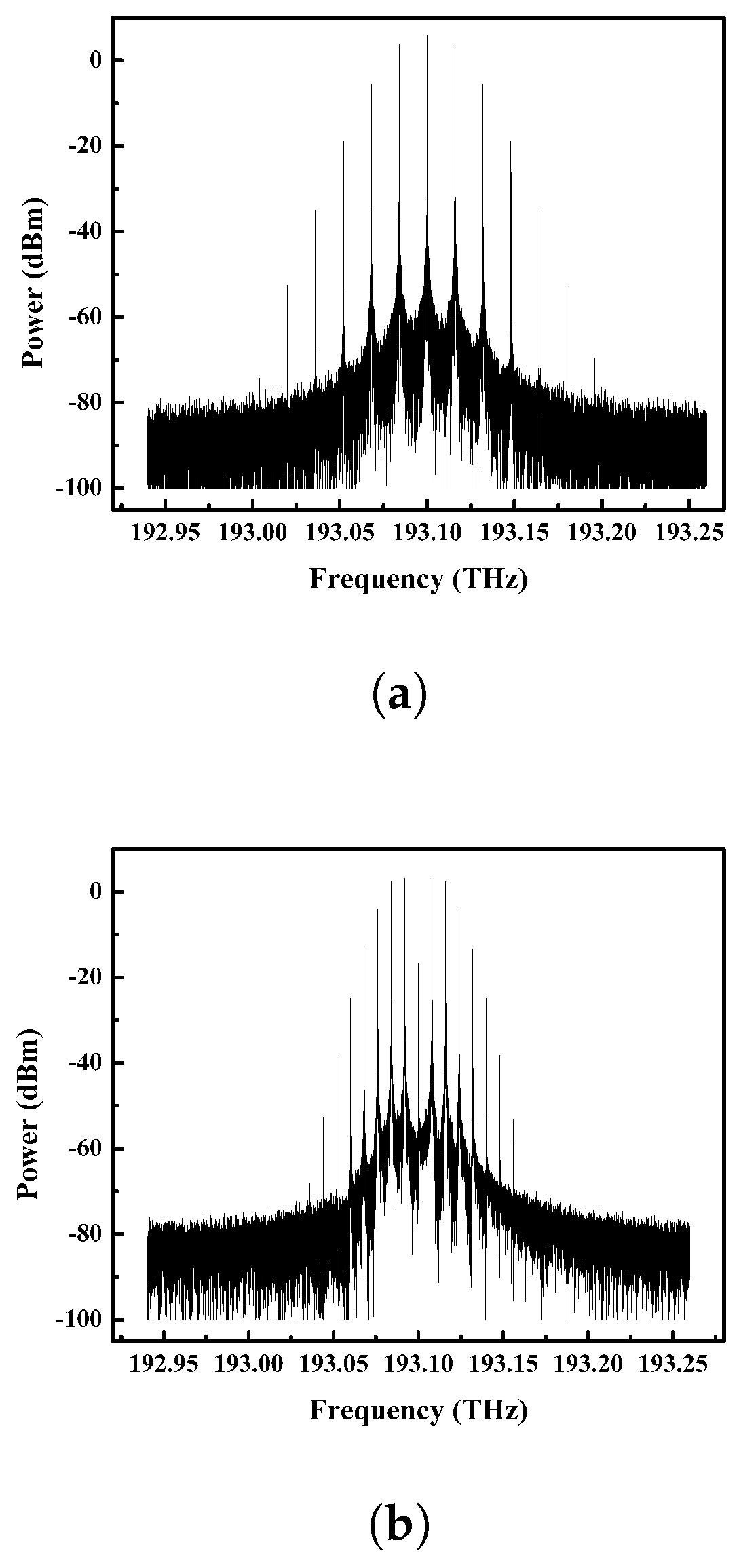
Figure 2a,b illustrate the optical spectrum at the output of the first FM driving with the frequency ( f m ) 16 GHz and 8 GHz, respectively.
The output of the first FM is sent to the second FM, which is driven by an RF signal with a frequency half that of the first FM. The optical field at the output of the second FM is expressed using Equations (3) and (4):
E f m 2 t = A 0 e j 2 π f c t · T F M 1 · e j β 2 c o s 2 π f 2 t .
E f m 2 t = A 0 e j 2 π f c t T F M n e t .
where β 2 denotes the modulation index of the second FM, f 2 denotes the frequency of RF signal driving the second FM, and T F M 1 denotes the transmittances of the first FM, and T F M n e t ( T F M 1 · e j β 2 c o s 2 π f 2 t ) provides the net transmittances of the first and second FM.
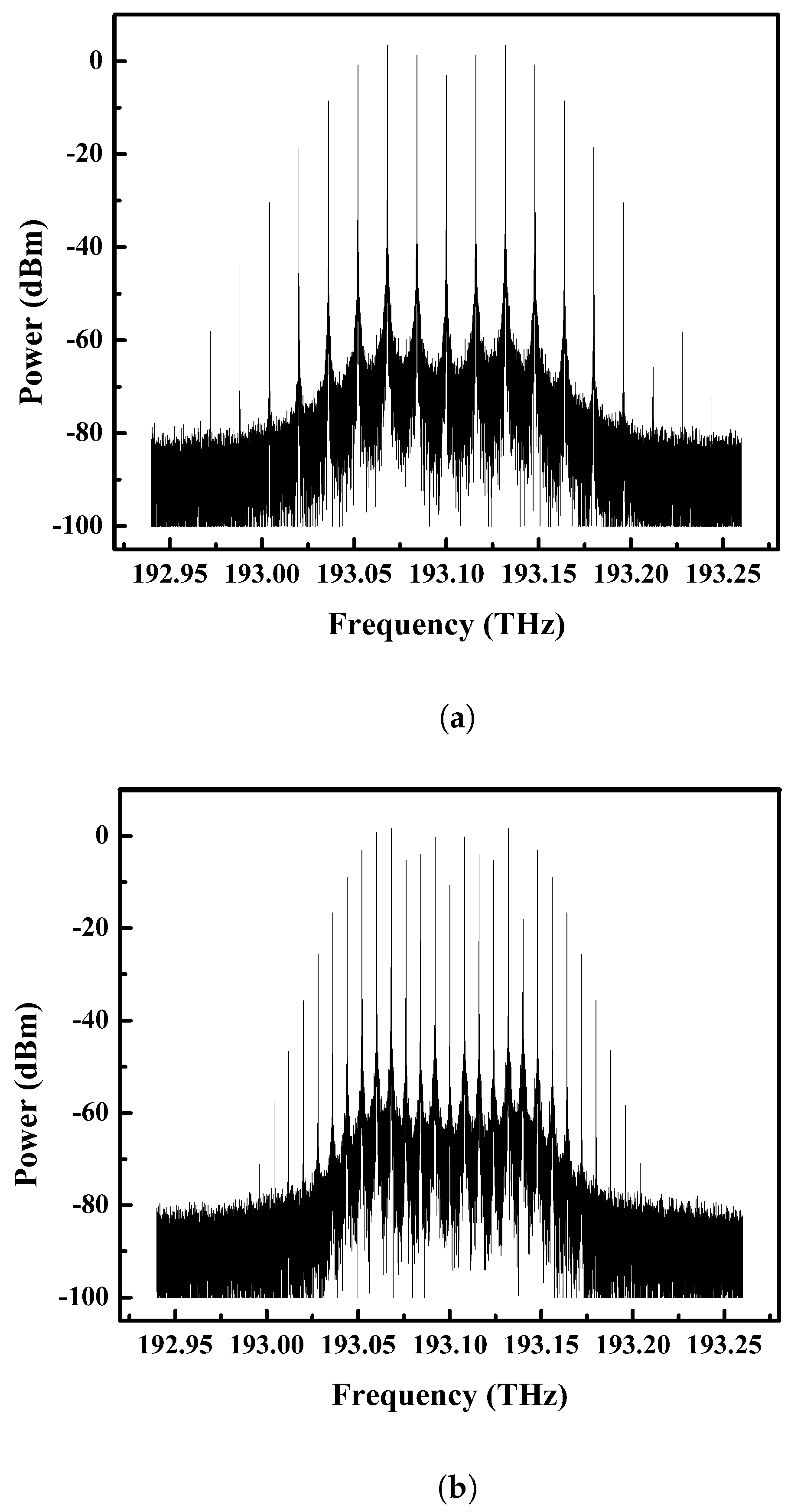
The second FM works as a subcarrier booster. However, the increase in the number of subcarriers is much smaller when the second FM is driven by a sinusoidal RF signal with the same frequency ( f m ) as the first FM (see Figure 3a,b). Nevertheless, if the second FM is driven by a sinusoidal RF signal at 8 GHz and 4 GHz with a frequency half that of the first FM ( f m /2), the comb lines grow to almost double, and the frequency separation is equal to the sinusoidal RF signal’s frequency ( f m /2), as seen in Figure 4a,b (proposed approach).
The optical spectrum at the output of the second FM has a maximum power deviation of ∼30 dB, as shown in Figure 3 and Figure 4. Thus it is further fed into the MZM, which works as an intensity modulator. The weak sidebands of the FM are excited by MZM, resulting in a flat spectrum at the output. The output of the second FM is sent into the optical input branch of the MZM, and an RF signal with the frequency f 3 = 2 f m drives the electrical input branch.
The optical field output of MZM operated by an RF sinusoidal signal v m z m ( t ) = V m c o s 2 π f 3 t is given by Equations (5)–(7):
E m z m ( t ) = 1 2 E f m 2 ( t ) e x p j π v m z m + v d c 2 + e x p j π v m z m + v d c v π .
E m z m ( t ) = E f m 2 t c o s π v m z m v d c + π v d c v π .
E m z m ( t ) = A 0 e j 2 π f c t T F M n e t c o s π V m c o s 2 π f 3 t v d c + π v d c v π .
where V m denotes the driving voltage of the RF signal, v d c denotes the DC bias voltage of the MZM, v π denotes the half-wave voltage of the MZM, and E f m 2 ( t ) is the optical field at the output of the second FM (shown in Equation (4)) [39].
The optical field at the output of the MZM can be represented by the Jacobi–Anger expansion shown in Equation (8):
e j x c o s θ = n = j n J n x e j n θ .
We can expand the E m z m (t) into the first kind of Bessel function [40] using Equation (9):
E m z m ( t ) = T F M n e t ( A 0 c o s φ n = 1 n J 2 n b 1 e x p j 2 π f c t + j 2 n · 2 π f 3 t A 1 s i n φ n = 1 n J 2 n + 1 b 1 e x p j 2 π f c t + j ( 2 n + 1 ) · 2 π f 3 t ) .
where J n ( b 1 ) denotes the nth-order Bessel function of the first kind, b 1 denotes the modulation index, b 1 = π V m v π , φ denotes the initial phase induced by the DC bias voltage, φ = π v d c v π .
By expanding T F M n e t using the Jacobi–Anger theorem, the optical field at the output of the MZM can be represented using Equation (10):
E m z m ( t ) = n = J n β 1 e j n 2 π f 1 t × n = J n β 2 e j n 2 π f 2 t × ( A 0 c o s φ n = 1 n J 2 n b 1 e x p j 2 π f c t + j 2 n · 2 π f 3 t A 1 s i n φ n = 1 n J 2 n + 1 b 1 e x p j 2 π f c t + j ( 2 n + 1 ) · 2 π f 3 t ) .
Finally, Equation (10) can be reduced to
E m z m ( t ) = J 1 β 1 e j 2 π f 1 t J 1 β 1 e j 2 π f 1 t + J 2 β 1 e j 2 π ( 2 f 1 ) t + J 2 β 1 e j 2 π ( 2 f 1 ) t + . . . . . × J 1 β 2 e j 2 π f 2 t J 1 β 2 e j 2 π f 2 t + J 2 β 2 e j 2 π ( 2 f 2 ) t + J 2 β 2 e j 2 π ( 2 f 2 ) t + . . . . . × ( A 0 c o s φ n = 1 n J 2 n b 1 e x p j 2 π f c t + j 2 n · 2 π f 3 t A 1 s i n φ n = 1 n J 2 n + 1 b 1 e x p j 2 π f c t + j ( 2 n + 1 ) · 2 π f 3 t ) .
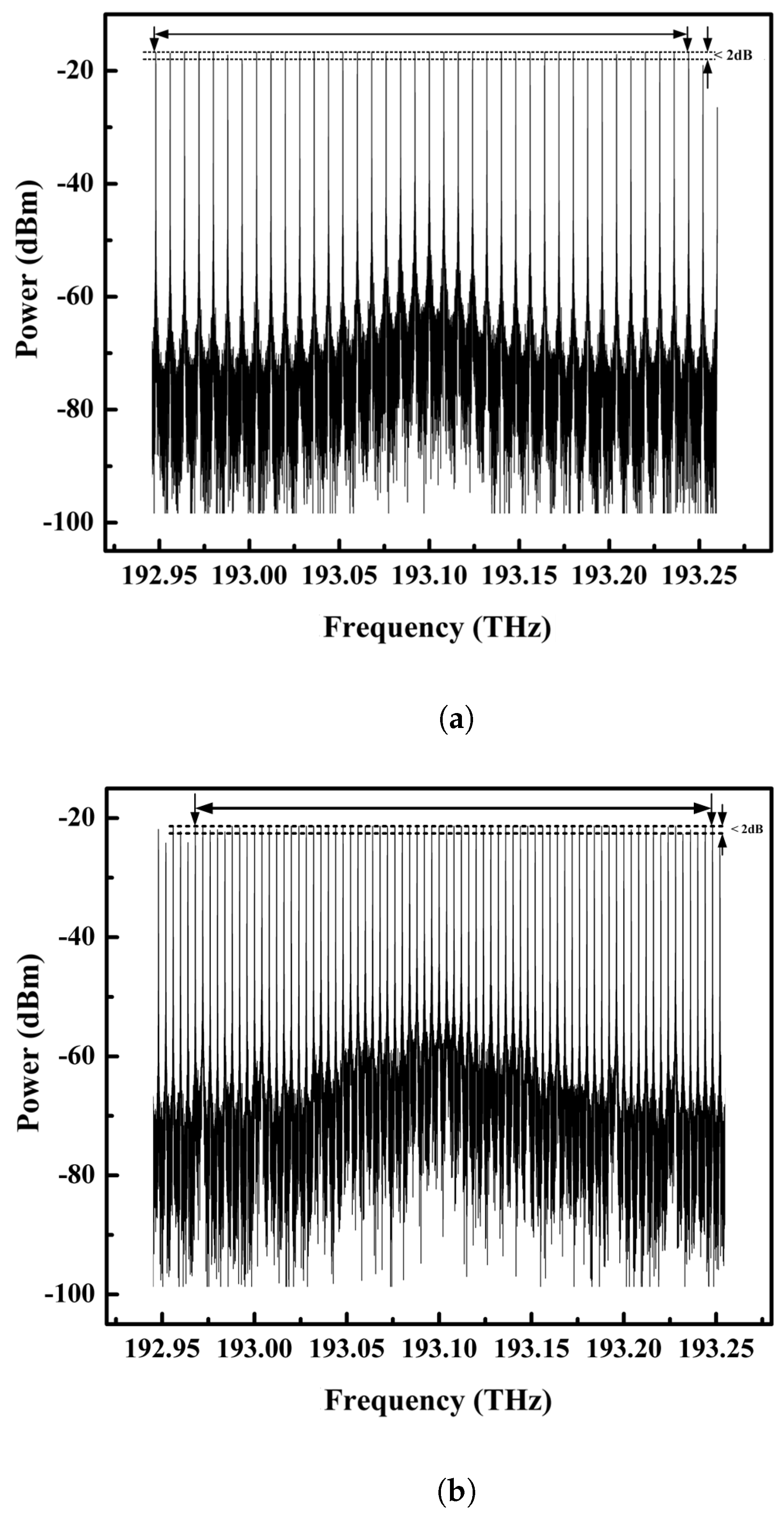
Equation (11) depicts the generated OFC at the output of the MZM. Figure 5a,b represent the optical spectrum at the output of the MZM when all modulators are driven by RF signals of frequencies f 1 = 16 GHz, f 2 = 16 GHz, and f 3 = 32 GHz and f 1 = 8 GHz, f 2 = 8 GHz, and f 3 = 16 GHz, respectively. As we can see, 19 comb lines spaced at 16 GHz at f m = 16 GHz and 37 comb lines spaced at 8 GHz at f m = 8 GHz are achieved within a power deviation of ∼1 dB in this scenario. Subcarriers decrease proportionally as subcarrier spacing increases, yet their power marginally increases.
However, if f 2 = f 1 /2, we obtain 38 comb lines spaced at 8 GHz at f m = 16 GHz. If we go from f m = 16 GHz to 8 GHz, the comb lines increase to 71 with a spacing of 4 GHz and within a power deviation of ∼2 dB (see Figure 6a and Figure 6b, respectively) (proposed approach). The frequency spacing of the produced OFC lines can be modified by adjusting the frequency of the RF signal and by adjusting the center frequency ( f c ) of the CW laser; the center frequency of the OFC can be adjusted as well.
We discovered that the second FM serves as a subcarrier booster after examining both scenarios (Figure 3 and Figure 4). However, power fluctuation is very high. We have also observed that the rise in the number of subcarriers is substantially lower when the second FM is driven with the sinusoidal frequency f 2 = f 1 than when the second FM is driven with f 2 = f 1 /2 (proposed approach). This is due to various frequency components canceling out when both FMs are driven by the same sinusoidal frequency of f 1 = f 2 GHz (as stated in Equation (11)). We have observed that the number of comb lines decreases, yet the power deviation of the spectrum improves when f 1 = f 2 is maintained. Moreover, the nonlinear impact of the intensity modulator (MZM) reduces the power fluctuations and results in a flattened output spectrum (Figure 6a,b).
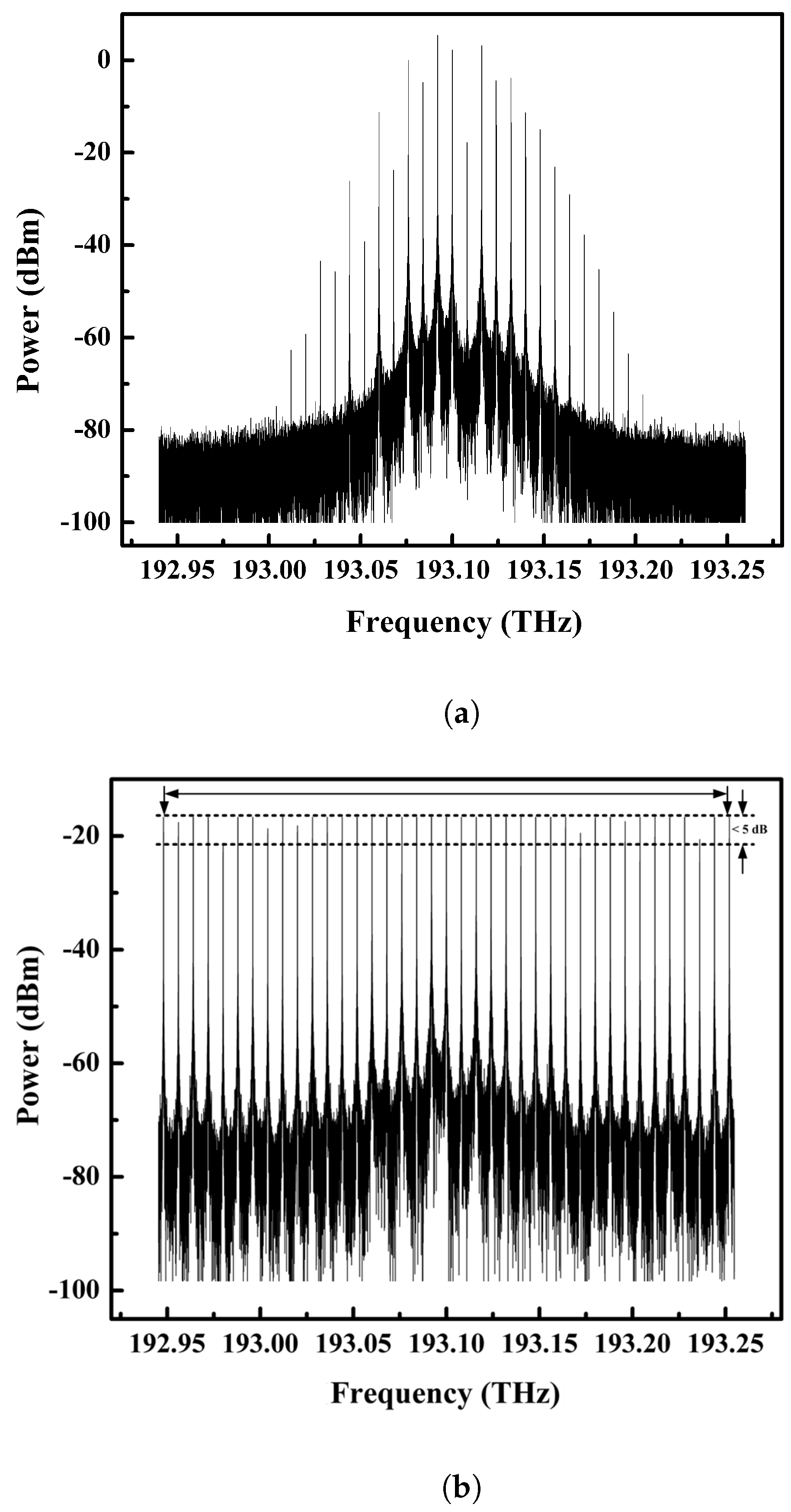
Finally, to analyze the effect of the RF signal’s phase on the performance of the OFC, we generated the comb lines by keeping the phase of all three RF sinusoidal signals at 90 degrees (Figure 7a,b). It was observed that the signal’s spectrum is not a stable OFC, and at certain points, the power deviation is very high (∼5 dB). The spectral flatness is limited by the phase of the sinusoidal signal RF. The spectral flatness can be further enhanced if the phase of the second FM’s RF signal is half that of the first. However, the MZM modulator somewhat compensates for the power fluctuations and improves spectral flatness.
Our proposed approach generates broad-bandwidth flat-top combs with 71 comb lines spaced at 4 GHz at f m = 8 GHz, and 38 comb lines spaced at 8 GHz at f m = 16 GHz, within 2 dB power fluctuation. Lastly, both the aforementioned cases are summarized in Table 1.

4. Conclusions

In this article, we propose a novel technique for obtaining a flat optical frequency comb by the serial cascading of two frequency modulators (FMs) followed by a single-drive Mach–Zehnder modulator (MZM). Using our proposed approach, 71 subcarriers spaced at 4 GHz were generated within a power deviation of ∼2 dB. The proposed method was also tested for f m = 16 GHz, and it is shown that this approach can work in all scenarios with lower power fluctuations. These many subcarriers with good spectral flatness can be employed as carriers to facilitate super-channel transmission, which serves as the building block for the next-generation intelligent optical transport network. However, some challenges occur during the experimental implementation of this approach, such as noise accumulation caused by the cascaded laser and modulators in the OFC. Particularly for optical communications applications, the accumulated noise affects the overall comb flatness. In order to lessen the influence of noise, phase noise reduction techniques could be used. Furthermore, carefully adjusting the driving characteristics of the modulators is necessary to generate an OFC with good spectral flatness. The system is inherently nonlinear, even in the most basic electro-optic modulator configuration, and when the RF signal consists only of a single frequency, the power distribution along each comb line is not even.

Author Contributions

Conceptualization, U.; Methodology, U.; Investigation, U. and R.K.; Writing—original draft, U. and R.K. All authors have read and agreed to the published version of the manuscript.

Funding

This research received no external funding.

Data Availability Statement

The data presented in this study are available on reasonable request from the corresponding author.

Conflicts of Interest

The authors declare no conflict of interest.

References

  1. Udem, T.; Holzwarth, R.; Hänsch, T.W. Optical frequency metrology. Nature 2002, 416, 233–237. [Google Scholar] [CrossRef]
  2. Fortier, T.; Baumann, E. 20 Years of developments in optical frequency comb technology and applications. Commun. Phys. 2019, 2, 153. [Google Scholar] [CrossRef] [Green Version]
  3. Capmany, J.; Novak, D. Microwave photonics combines two worlds. Nat. Photonics 2007, 1, 319. [Google Scholar] [CrossRef]
  4. Chen, C.; Zhang, C.; Zhang, W.; Jin, W.; Qiu, K. Scalable and reconfigurable generation of flat optical comb for WDM-based next-generation broadband optical access networks. Opt. Commun. 2014, 321, 16–22. [Google Scholar] [CrossRef]
  5. Schibli, T.; Minoshima, K.; Hong, F.L.; Inaba, H.; Onae, A.; Matsumoto, H.; Hartl, I.; Fermann, M. Frequency metrology with a turnkey all-fiber system. In Proceedings of the Ultrafast Phenomena XIV: Proceedings of the 14th International Conference, Niigata, Japan, 25–30 July 2004; Springer: Berlin/Heidelberg, Germany, 2005; pp. 843–845. [Google Scholar]
  6. Cingöz, A.; Yost, D.C.; Allison, T.K.; Ruehl, A.; Fermann, M.E.; Hartl, I.; Ye, J. Direct frequency comb spectroscopy in the extreme ultraviolet. Nature 2012, 482, 68–71. [Google Scholar] [CrossRef] [Green Version]
  7. Jia, S.; Yu, X.; Hu, H.; Yu, J.; Guan, P.; Da Ros, F.; Galili, M.; Morioka, T.; Oxenløwe, L.K. THz photonic wireless links with 16-QAM modulation in the 375–450 GHz band. Opt. Express 2016, 24, 23777–23783. [Google Scholar] [CrossRef] [Green Version]
  8. Zhang, H.; Chang, B.; Li, Z.; Liang, Y.; Qin, C.; Wang, C.; Xia, H.; Tan, T.; Yao, B. Optical frequency combs: From principles to applications. J. Electron. Sci. Technol. 2022, 20, 120–148. [Google Scholar] [CrossRef]
  9. Davila-Rodriguez, J.; Bagnell, K.; Delfyett, P.J. Frequency stability of a 10 GHz optical frequency comb from a semiconductor-based mode-locked laser with an intracavity 10,000 finesse etalon. Opt. Lett. 2013, 38, 3665–3668. [Google Scholar] [CrossRef] [PubMed]
  10. Kippenberg, T.J.; Gaeta, A.L.; Lipson, M.; Gorodetsky, M.L. Dissipative Kerr solitons in optical microresonators. Science 2018, 361, eaan8083. [Google Scholar] [CrossRef] [Green Version]
  11. Qu, K.; Zhao, S.; Li, X.; Zhu, Z.; Liang, D.; Liang, D. Ultra-flat and broadband optical frequency comb generator via a single Mach–Zehnder modulator. IEEE Photonics Technol. Lett. 2016, 29, 255–258. [Google Scholar] [CrossRef]
  12. Morohashi, I.; Sakamoto, T.; Sotobayashi, H.; Kawanishi, T.; Hosako, I. Broadband optical comb generation using mach-zehnder-modulator-based flat comb generator with feedback loop. In Proceedings of the 36th European Conference and Exhibition on Optical Communication, Turin, Italy, 19–23 September 2010; pp. 1–3. [Google Scholar]
  13. Wang, D.; Zhang, M.; Li, Z.; Li, J.; Fu, M.; Cui, Y.; Chen, X. Modulation format recognition and OSNR estimation using CNN-based deep learning. IEEE Photonics Technol. Lett. 2017, 29, 1667–1670. [Google Scholar] [CrossRef]
  14. Sharma, V.; Singh, S. Cross-phase modulation based ultra-flat 90-line optical frequency comb generation. Opt. Quantum Electron. 2021, 53, 657. [Google Scholar] [CrossRef]
  15. Sakamoto, T.; Kawanishi, T.; Izutsu, M. Widely wavelength-tunable ultra-flat frequency comb generation using conventional dual-drive Mach-Zehnder modulator. Electron. Lett. 2007, 43, 1039–1040. [Google Scholar] [CrossRef]
  16. Ozharar, S.; Quinlan, F.; Ozdur, I.; Gee, S.; Delfyett, P. Ultraflat optical comb generation by phase-only modulation of continuous-wave light. IEEE Photonics Technol. Lett. 2007, 20, 36–38. [Google Scholar] [CrossRef]
  17. Mishra, A.K.; Schmogrow, R.; Tomkos, I.; Hillerkuss, D.; Koos, C.; Freude, W.; Leuthold, J. Flexible RF-based comb generator. IEEE Photonics Technol. Lett. 2013, 25, 701–704. [Google Scholar] [CrossRef]
  18. Yamamoto, T.; Komukai, T.; Suzuki, K.; Takada, A. Multicarrier light source with flattened spectrum using phase modulators and dispersion medium. J. Light. Technol. 2009, 27, 4297–4305. [Google Scholar] [CrossRef]
  19. Wu, R.; Supradeepa, V.; Long, C.M.; Leaird, D.E.; Weiner, A.M. Generation of very flat optical frequency combs from continuous-wave lasers using cascaded intensity and phase modulators driven by tailored radio frequency waveforms. Opt. Lett. 2010, 35, 3234–3236. [Google Scholar] [CrossRef] [PubMed] [Green Version]
  20. Dou, Y.; Zhang, H.; Yao, M. Improvement of flatness of optical frequency comb based on nonlinear effect of intensity modulator. Opt. Lett. 2011, 36, 2749–2751. [Google Scholar] [CrossRef]
  21. Dou, Y.; Zhang, H.; Yao, M. Generation of flat optical-frequency comb using cascaded intensity and phase modulators. IEEE Photonics Technol. Lett. 2012, 24, 727–729. [Google Scholar] [CrossRef]
  22. Wang, Q.; Huo, L.; Xing, Y.; Zhou, B. Ultra-flat optical frequency comb generator using a single-driven dual-parallel Mach–Zehnder modulator. Opt. Lett. 2014, 39, 3050–3053. [Google Scholar] [CrossRef]
  23. Zhang, F.; Wu, J.; Li, Y.; Lin, J. Flat optical frequency comb generation and its application for optical waveform generation. Opt. Commun. 2013, 290, 37–42. [Google Scholar] [CrossRef]
  24. Hmood, J.K.; Emami, S.D.; Noordin, K.A.; Ahmad, H.; Harun, S.W.; Shalaby, H.M. Optical frequency comb generation based on chirping of Mach–Zehnder modulators. Opt. Commun. 2015, 344, 139–146. [Google Scholar] [CrossRef]
  25. Yan, X.; Zou, X.; Pan, W.; Yan, L.; Azaña, J. Fully digital programmable optical frequency comb generation and application. Opt. Lett. 2018, 43, 283–286. [Google Scholar] [CrossRef]
  26. Wang, Z.; Ma, M.; Sun, H.; Khalil, M.; Adams, R.; Yim, K.; Jin, X.; Chen, L.R. Optical frequency comb generation using CMOS compatible cascaded Mach–Zehnder modulators. IEEE J. Quantum Electron. 2019, 55, 1–6. [Google Scholar] [CrossRef]
  27. Ullah, S.; Ullah, R.; Zhang, Q.; Khalid, H.A.; Memon, K.A.; Khan, A.; Tian, F.; Xiangjun, X. Ultra-wide and flattened optical frequency comb generation based on cascaded phase modulator and LiNbO3-MZM offering terahertz bandwidth. IEEE Access 2020, 8, 76692–76699. [Google Scholar] [CrossRef]
  28. Cui, Y.; Wang, Z.; Zuo, X.; Xu, Y.; Jiang, Y.; Yu, J.; Huang, Z. Flat optical frequency comb generation by using one DPMZM and superposed harmonics. Opt. Commun. 2023, 531, 129223. [Google Scholar] [CrossRef]
  29. Muhanad Fadhel, M.; Rashid, H.; Essa Hamzah, A.; Dzulkefly Zan, M.S.; Abd Aziz, N.; Arsad, N. Flat frequency comb generation employing cascaded single-drive Mach–Zehnder modulators with a simple analogue driving signal. J. Mod. Opt. 2021, 68, 536–541. [Google Scholar] [CrossRef]
  30. Fan, Y.; Li, P. Optical frequency comb based on cascaded MZM-EAM with Gaussian-shaped pulse signal. Opt. Eng. 2021, 60, 056106. [Google Scholar] [CrossRef]
  31. Sharma, V.; Singh, S. Design of tunable optical frequency comb generation based on electro-optic modulator. Photonic Netw. Commun. 2022, 44, 133–140. [Google Scholar] [CrossRef]
  32. Demirtzioglou, I.; Lacava, C.; Bottrill, K.R.; Thomson, D.J.; Reed, G.T.; Richardson, D.J.; Petropoulos, P. Frequency comb generation in a silicon ring resonator modulator. Opt. Express 2018, 26, 790–796. [Google Scholar] [CrossRef] [PubMed]
  33. Zhang, M.; Wang, C.; Buscaino, B.; Shams-Ansari, A.; Kahn, J.M.; Loncar, M. Electro-optic frequency comb generation in ultrahigh-Q integrated lithium niobate micro-resonators. In Proceedings of the CLEO: QELS_Fundamental Science, San Jose, CA, USA, 13–18 May 2018; Optica Publishing Group: Washington, DC, USA, 2018; p. FW3E-4. [Google Scholar]
  34. Kulagin, V.; Valuev, V.; Kontorov, S.; Kornienko, V.; Prokhorov, D.; Cherepenin, V. Optical frequency comb in optoelectronic oscillator with delay line and microresonator. In Proceedings of the 2022 International Conference Laser Optics (ICLO), Saint Petersburg, Russia, 20–24 June 2022; p. 1-1. [Google Scholar]
  35. Wu, X.; Tsang, H. Flat-top frequency comb generation with silicon microring modulator and filter. In Proceedings of the 2017 Conference on Lasers and Electro-Optics (CLEO), San Jose, CA, USA, 14–19 May 2017; pp. 1–2. [Google Scholar]
  36. Liu, Y.; Wu, S.; Shen, X. Ultra-Flat Optical Frequency Comb Generation Based on Electro-Optic Intensity Modulator with Digital Driving Signal. 2022. Available online: https://www.researchsquare.com/article/rs-1137183/v1 (accessed on 11 May 2022).
  37. Cui, Y.; Wang, Z.; Xu, Y.; Jiang, Y.; Yu, J.; Huang, Z. Generation of flat optical frequency comb using cascaded PMs with combined harmonics. IEEE Photonics Technol. Lett. 2022, 34, 490–493. [Google Scholar] [CrossRef]
  38. Shen, J.; Wu, S.; Li, D. Ultra-flat optical frequency comb generation based on phase modulation with simple digital driving signal. Optik 2019, 198, 163254. [Google Scholar] [CrossRef]
  39. Li, Y.; Chen, Y.W.; Zhou, W.; Tang, X.; Shi, J.; Zhao, L.; Yu, J.; Chang, G.K. D-band mm-wave SSB vector signal generation based on cascaded intensity modulators. IEEE Photonics J. 2020, 12, 1–11. [Google Scholar] [CrossRef]
  40. Lin, C.T.; Lin, Y.M.; Chen, J.J.; Dai, S.P.; Shih, P.T.; Peng, P.C.; Chi, S. Optical direct-detection OFDM signal generation for radio-over-fiber link using frequency doubling scheme with carrier suppression. Opt. Express 2008, 16, 6056–6063. [Google Scholar] [CrossRef] [PubMed]
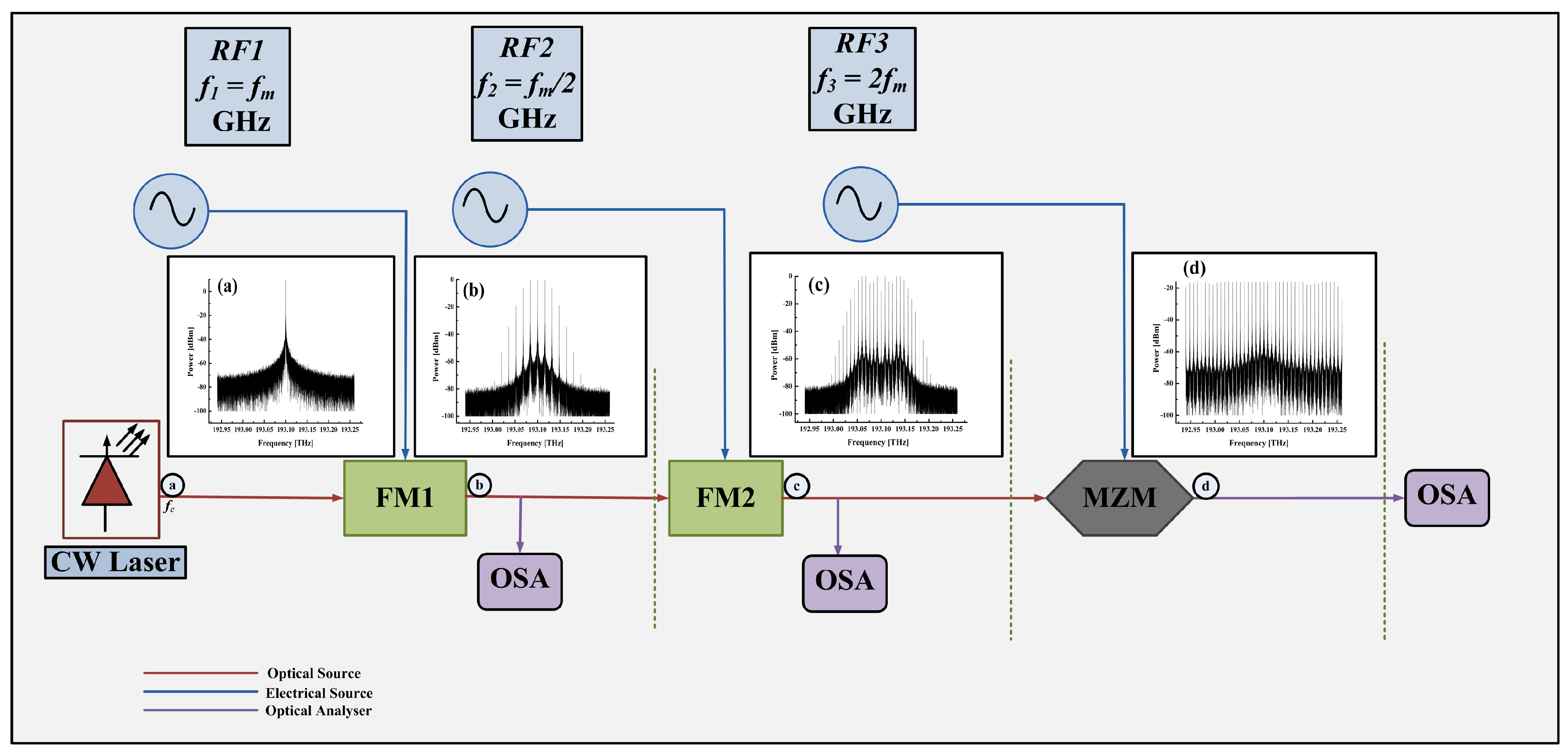
Figure 1. System setup for generating the OFC by cascading modulators. CW, continuous wave laser; RF, radio frequency; FM, frequency modulator; MZM, Mach–Zehnder modulator; OSA, optical spectrum analyzer.
Electronics 12 02762 g001
Figure 2. OFC spectrum at the output of first FM. (a) f 1 = f m = 16 GHz and (b) f 1 = f m = 8 GHz.
Electronics 12 02762 g002
Figure 3. OFC spectrum at the output of second FM. (a) f 2 = f 1 = 16 GHz and (b) f 2 = f 1 = 8 GHz.
Electronics 12 02762 g003
Figure 4. OFC spectrum at the output of second FM. (a) f 2 = f 1 /2 = 8 GHz and (b) f 2 = f 1 /2 = 4 GHz.
Electronics 12 02762 g004
Figure 5. OFC spectrum at the output of MZM. (a) f 1 = 16 GHz, f 2 = 16 GHz, and f 3 = 32 GHz and (b) f 1 = 8 GHz, f 2 = 8 GHz, and f 3 = 16 GHz.
Electronics 12 02762 g005
Figure 6. The OFC spectrum at the output of the MZM (proposed approach). (a) f 1 = 16 GHz, f 2 = 8 GHz, and f 3 = 32 GHz (38 comb lines) and (b) f 1 = 8 GHz, f 2 = 4 GHz, and f 3 = 16 GHz (71 comb lines).
Electronics 12 02762 g006
Figure 7. (a) OFC spectrum at the output of the second FM ( f 2 = f 1 /2 = 8 GHz) with an RF sinusoidal phase of 90 degrees. (b) The optical spectrum at the output of the MZM when all modulators are driven by RF signals with frequencies f 1 = 16 GHz, f 2 = 8 GHz, and f 3 = 32 GHz, and the phase of all three RF sinusoidal signals is 90 degrees.
Electronics 12 02762 g007
Table 1. First case vs. second case (proposed).
ParametersFirst CaseSecond Case (Proposed)
RF signal frequencies ( f 1 , f 2 , and f 3 ) f 1 = f m  GHz, f 2 = f m  GHz,
and f 3 = 2 f m  GHz
f 1 = f m  GHz, f 2 = f m /2 GHz,
and f 3 = 2 f m  GHz
Spectral componentsLessMore
Number of comb lines ( f m = 16 GHz)1937
Number of comb lines ( f m = 8 GHz)3871
Subcarrier Spacing ( f m = 16 GHz and 8 GHz)16 GHz, 8 GHz8 GHz, 4 GHz
Power deviation<1 dB<2 dB
Disclaimer/Publisher’s Note: The statements, opinions and data contained in all publications are solely those of the individual author(s) and contributor(s) and not of MDPI and/or the editor(s). MDPI and/or the editor(s) disclaim responsibility for any injury to people or property resulting from any ideas, methods, instructions or products referred to in the content.