1. Introduction
In recent years, people’s growing demand for a better life has led to higher and higher requirements for automotive “intelligence”, which cannot be achieved without the support of various auxiliary electrical equipment, and the corresponding increase in electricity consumption has resulted in new requirements for automotive generators. Permanent magnet motors achieve high-power density and high efficiency while often leading to an increase in cogging torque [
1]. The cogging torque is an inherent property of permanent magnet motors that can lead to fluctuations in output electromagnetic torque, motor vibration, and noise [
2,
3]. Therefore, how to suppress cogging torque, reduce motor torque pulsation, and improve stability has become a hot issue in research on permanent magnet generators.
The size of the cogging torque is mainly related to two factors, namely, air-gap permeance and the residual magnetism density of the permanent magnet [
4]. Therefore, weakening the motor cogging torque can be optimized by changing the structural parameters of the stator and rotor. Regarding stator structure optimization, studies by [
5,
6] established an analytical model of cogging torque including stator tooth width and studied the influence law between unequal stator tooth width and cogging torque. The results showed that motor cogging torque could be suppressed by optimizing the stator slot width, but the method led to an increase in unbalanced magnetic pull. A study by [
7] used an analytical method to study the cogging torque generated by a single slot, and weakened the motor cogging torque by grouping offsets to the stator slots; however, this method changed the distribution of the windings, which resulted in an asymmetric counter potential waveform. Studies by [
8,
9] proposed a method to optimize the motor tooth cogging torque by opening an auxiliary slot on the stator. Although this method was less difficult to machine compared with the stator slant slot [
10], it did reduce the overload capacity of the motor.
Compared with changing the stator structure, the rotor core is made of laminated silicon steel sheets and it is simple to change its structural parameters. A study by [
11] achieved the purpose of weakening the cogging torque by optimizing the pole-slot fit to increase the number of harmonic periods of the cogging torque. In [
12], it was proposed to change the remanence distribution of permanent magnet by chipping the angle poles, which in turn affected the cogging torque. However, no method was given to determine the optimal chipping position and the size of the chipping angle. The authors of [
13] optimized built-in permanent magnet motor cogging torque by using skewed stacked rotor silicon steel sheets and the asymmetric permanent magnet slot method and reduced the motor torque fluctuation with the help of the Taguchi method. In [
14], a semi-analytical model of the pole segmented motor was developed and the optimal combination of the widths of each segment in the pole axis was determined by using a multi-objective particle swarm optimization method. However, these two methods were too complex and not suitable for large-scale production. In studies by [
15,
16,
17], the pole offset method was used to weaken the cogging torque, and different optimization algorithms were used to determine the optimal angle of pole offset. This method was simple, did not affect the symmetry of armature counter potential, and was especially effective for optimizing the torque of the tooth slot of small power few-pole motors.
All of the above methods can optimize the cogging torque of PM motors, but these methods only use cogging torque as a single optimization objective in the optimization process. Permanent magnet generators are not designed to optimize a single index, and other electromagnetic properties may not be ideal when the cogging torque is minimized. Therefore, in this paper, we propose a multi-objective optimization approach to achieve the “relative” optimal design of a permanent magnet generator including induction potential amplitude, air-gap flux density, and cogging torque.
2. Magnetic Circuit Analysis
With high efficiency, high-power density, and simple structure, permanent magnet synchronous motors are widely used in various fields such as energy, transportation, and chemical industries [
18]. Surface-mounted permanent magnet motors with fast dynamic response and low torque pulsation, but with low power density as well as the risk of shedding in high-speed operating environments, have been gradually phased out [
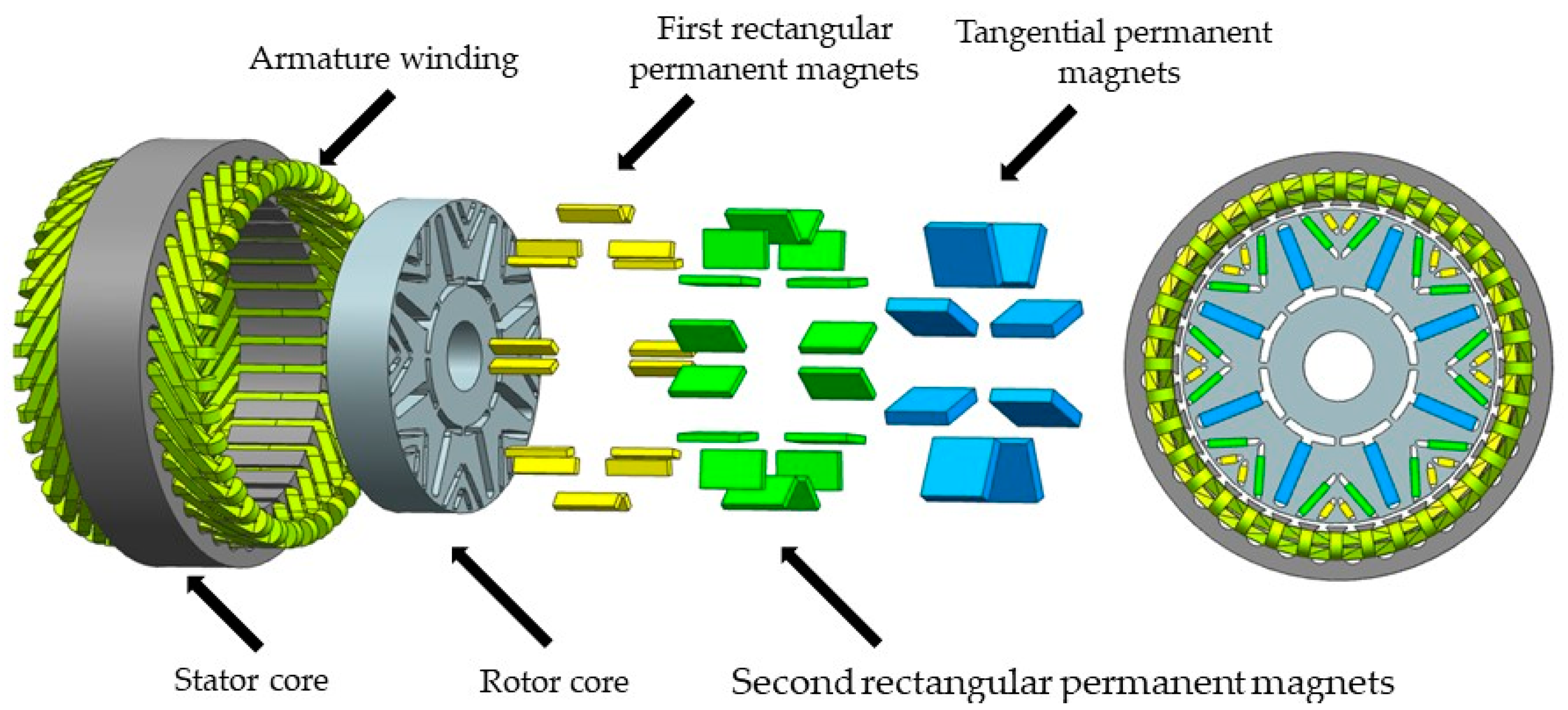
19]. Built-in permanent magnet generators are mainly divided into two types, i.e., tangential and radial, according to the arrangement of permanent magnets. The structure of the tangential arrangement of permanent magnets has better magnetization and a high power factor of the whole machine. However, the interval between the rotor poles of the motor is larger, the air-gap flux density distribution is not uniform, and the torque ripple is relatively large in the low-speed operating range [
20]. The air-gap flux density of the structure with radial arrangement of permanent magnets is relatively low and is mainly used in micro- and low-power generators [
21]. Therefore, in this paper, we propose a radial-tangential built-in combined permanent magnet pole generator to achieve high air-gap flux density while ensuring uniform magnetic field distribution, as shown in
Figure 1.
In order to compare the magnetization effect of different structures, a V-shaped structure composed of second rectangular type permanent magnets can be replaced by a semi-circle structure, and the magnetic circuits of the two structures are basically the same. In this design, the magnetic circuit distribution is analyzed with a double V-shaped structure as an example. As shown in
Figure 2, there are three main magnetic circuits in the double V-type combined permanent magnet pole generator, which are:
Main magnetic circuit 1: tangential permanent magnets, silicon steel sheet, main air gap, stator core, main air gap, silicon steel sheet, tangential permanent magnets;
Main magnetic circuit 2: tangential permanent magnets, silicon steel sheet, first rectangular permanent magnets, silicon steel sheet, main air gap, stator core, main air gap, silicon steel sheet, first rectangular permanent magnets, silicon steel sheet, tangential permanent magnets;
Main magnetic circuit 3: tangential permanent magnets, silicon steel sheet, first rectangular permanent magnets, silicon steel sheet, second rectangular permanent magnets, silicon steel sheet, main air gap, stator core, main air gap, silicon steel sheet, second rectangular permanent magnets, silicon steel sheet, first rectangular permanent magnets, silicon steel sheet, tangential permanent magnets.
The generation of leakage flux is mainly due to the processing needs of the silicon steel sheet and the structural strength of the rotor core. The magnetic separation slot of the permanent magnet near the outer circle of the rotor needs to maintain a distance of about 1.5~2 mm from the outer circle of the rotor. The permeability of the silicon steel sheet is much larger than the air gap, which causes part of the magnetic field to reach the stator without crossing the air gap, and a closed circuit is formed inside the rotor. There is also a part of the leakage flux gathered in the end of the tangential permanent magnet near the center of the rotor. In order to reduce the leakage here, a rectangular magnetic separation slot is added at the bottom of each tangential permanent magnet. At the same time, during the generator design process, the length of the tangential permanent magnet is increased to offset this part of the leakage, so this part of the leakage is not considered during the magnetic circuit analysis.
Based on the above analysis, the equivalent magnetic circuit diagram of the generator can be established, as shown in
Figure 3. In this paper, the magnetic permeability of the rotor core is assumed to be linear.
In
Figure 3,
Fpt,
Fpf, and
Fps are the magnetic potential generated by the tangential permanent magnet, the first rectangular permanent magnets, and the second rectangular permanent magnets, respectively;
Fd is the magnetic momentum generated by the stator winding;
Gpt,
Gpf, and
Gps are the tangential permanent magnet permeability, the first rectangular permanent magnet permeability, and the second rectangular permanent magnet permeability, respectively;
Gcg is the magnetic conductance at the main air gap;
Ggt is the magnetic conductance at the stator teeth;
Gsy is the magnetic conductance at the stator yoke;
Glt,
Glf, and
Gls are the leakage permeability generated by the first main magnetic circuit, the second main magnetic circuit, and the third main magnetic circuit, respectively.
According to the magnetic circuit relationship shown in
Figure 3, it is obtained that:
In the formula,
Φsy1,
Φsy2, and
Φsy3 are the main fluxes through the stator teeth under the three main magnetic circuits, respectively.
Φsy is the sum of the main fluxes through the stator teeth of the main flux.
Φlt,
Φlf, and
Φls are the magnetic fluxes of the three main magnetic circuits, respectively.
Φpt1,
Φpt2, and
Φpt3 are the main fluxes of the tangential permanent magnets into the three main magnetic circuits, respectively.
where the coefficients
K,
Q, and
X are:
where the magnetic potential of the tangential permanent magnet
Fpt is:
where
B is the remanent magnetic inductance of the tangential permanent magnet,
hpt is the length of the magnetization direction of the tangential permanent magnet,
μ0 is the vacuum permeability, and
μp is the relative permeability of the tangential permanent magnet.
The magnetic permeability
Gpt of the tangential permanent magnet is:
where
lpt is the width of the tangential permanent magnet and
l is the axial length of the rotor.
The leakage permeability
Glt of the first magnetic circuit is:
where
μr is the relative permeability of the rotor core and
rpv is the radius of the leakage path at the end of the tangential permanent magnet.
The formulae for calculating the permeability
Gpc and leakage permeability
Glc of semi-circular permanent magnets are different from those of rectangular permanent magnets, and they are as follows:
where
rc is the inner radius of the semi-circular permanent magnet,
hc is the width of the semi-circular permanent magnet,
P is the number of generator poles,
rr is the outer radius of the rotor, and
σ is the pole arc factor.
The cogging torque is:
where
θ is the angle of the center of the rotor corresponding to the outer arc.
The no-load induced electromotive force of the generator is:
where
N is the number of turns of the induction coil.
The rest of the generator potential, permeability, and other parameters are calculated in a similar way, and therefore are not repeated in this paper.
3. Finite Element Verification
In this study, we took a three-phase, eight-pole, 36-slot double V-type combined permanent magnet pole generator (rated power 1 kW, rated voltage 72 V, rated speed 1500 r/min) as an example, and used Maxwell finite analysis software to build a two-dimensional simulation model to verify the accuracy of the mathematical model.
Table 1 shows some structural parameters of the double V-type combined permanent magnet pole generator.
Figure 4 shows the magnetic flux density cloud of the double V-type combined permanent magnet pole generator.
To verify the correctness of the calculation results of the equivalent magnetic circuit method, the main and leakage fluxes of the magnetic fields of each part of the two structures are calculated by finite element analysis. The comparison of the calculation results of the equivalent magnetic circuit method and the finite element method is shown in
Table 2.
Using the established equivalent magnetic circuit model, the permanent magnet field leakage is considered only at the end leakage and equated to the permanent magnet length, and the effective length of the permanent magnet is calculated as the total length of the permanent magnet minus the equivalent length of the leakage. The equivalent magnetic circuit model is solved to obtain the flux of each part of the permanent magnetic circuit. Meanwhile, to verify the correctness of the calculation results of the equivalent magnetic circuit method, the main and leakage fluxes of the magnetic fields of each part of the two structures are calculated by finite element analysis. The comparison of the calculation results of the equivalent magnetic circuit method and the finite element method is shown in
Table 2. From the calculation results, the flux of each part calculated by the equivalent magnetic circuit method is slightly smaller than that of the finite element method, but the difference between them is not large. It also verifies the validity of the calculation results of the equivalent magnetic circuit method. The main fluxes per pole of the double V-type combined permanent magnet structure and the semi-circular permanent magnet structure obtained by the equivalent magnetic circuit method are 1.257 × 10
−4 Wb and 1.227 × 10
−4 Wb, respectively. The double V-type combined permanent magnet structure has higher rotor flux density, and the leakage fluxes of the double V-type combined permanent magnet structure and the semi-circular permanent magnet structure are 8.154 × 10
−5 Wb and 6.550 × 10
−5 Wb, respectively, as calculated by the finite element method. Therefore, the semi-circular permanent magnet structure has less leakage flux.
Figure 5 shows the radial magnetic density distribution in the middle of the air gap. It can be seen from
Figure 5 that the maximum value of air-gap flux density of the double V-type combined permanent magnet pole generator is 1.246 T. The waveform basically has a sinusoidal distribution, but there is a certain depression at the wave crest. This is mainly influenced by the principle of minimum reluctance, the magnetic lines of force passing through the second rectangular permanent magnets in the third main magnetic circuit will choose the shortest path out of the stator into the air gap. It leads to magnetic field saturation, only at the opening of the two second rectangular permanent magnets, being biased towards the middle of the path longer reluctance distribution. So, the magnetic field at the middle of each pole will appear as a certain depression.
The radially magnetized semi-circular permanent magnets are used instead of the second rectangular permanent magnets. Guided by the magnetic field of the semi-circular permanent magnets themselves, the magnetic lines of force pass through the semi-circular permanent magnets and gather at the center of the circle, effectively compensating for the depression of the air-gap flux density at the wave peak. The maximum value of this curve is 1.271 T as can be seen from the air-gap magnetic density distribution shown in
Figure 5.
The Fourier decomposition of the radial magnetic density curve shown in
Figure 5 leads to the histogram of the radial magnetic density harmonic distribution shown in
Figure 6. From
Figure 6, it can be seen that the base wave amplitude of the air-gap flux density of the double V-type combined permanent magnet is 1.093 T, and the aberration rate is 27.42%. The base wave amplitude of the air-gap flux density of the semi-circular permanent magnet is 1.098 T, and the aberration rate is 24.55%. The base wave amplitude of the air-gap flux density of the two is basically the same, but the aberration rate of the double V-type combined permanent magnet is 11.7% larger than that of the semi-circular permanent magnet.
Figure 7 shows the graphs of the gearing torque curves for the two structures. As can be seen in
Figure 7, the maximum value of cogging torque is 367.35 m·Nm for the double V-type combined permanent magnet pole generator and 587.19 m·Nm for the semi-circular-type combined permanent magnet pole generator, which is an increase of 59.9%. This is due to the fact that semi-circular permanent magnets are magnetized in such a way that they have a stronger magnetizing capacity which leads to a significant increase in the cogging torque of the semi-circular type combined permanent magnet pole generator.
Figure 8 shows a comparison of the A-phase no-load induction potential waveforms, from which it can be seen that the A-phase no-load induction potential waveforms of the two structures are basically sinusoidal, but there are differences in the amplitude of the two curves. The maximum value of A-phase no-load induction potential is 79.67 V for the double V-type and 87.58 V for the semi-circular structure. Fourier decomposition of the A-phase no-load induced electromotive force waveform leads to a histogram of the A-phase no-load induced electromotive force harmonic distribution as shown in
Figure 9. The base wave amplitude of the A-phase no-load induction potential of the double V-type is 77.23 V, and the aberration rate is 8.4%. The base wave amplitude of the A-phase no-load induction potential of the semi-circular structure is 85.09 V, and the aberration rate is 9.1%.
Compared with the semi-circular permanent magnet pole structure, the maximum value of the air-gap flux density is basically equal. However, due to the principle of minimum reluctance, the air-gap flux density waveform has a certain depression at the peak and trough, and the waveform sinusoid is relatively poor, which leads to a lower quality of the output waveform. However, in terms of cogging torque, the semi-circular permanent magnets guide the magnetic lines to gather at the center of each pole, resulting in a significant increase in cogging torque, and excessive cogging torque will increase noise and vibration during generator operation. Therefore, in order to take into consideration the advantages of both, that is, on the basis of having a good air-gap flux density waveform sine waveform, the cogging torque is reduced as much as possible. This design proposes a combined permanent magnet pole generator with V-shaped and semi-circular permanent magnets alternately arranged.
4. Structure Optimization
The result of Equation (8) shows that the cogging torque is a product of the interaction between the air-gap flux density and the stator teeth, and since the air-gap flux density varies periodically, it leads to the same periodicity of the cogging torque waveform. The cogging torque of the generator can be regarded to be the superposition of the cogging torque generated by all individual poles. For the combined pole with symmetrical poles, the cogging torque curve is the superposition of the cogging torque of each pole with the same phase and frequency, and the total cogging torque peak after the superposition is larger. In the case of a non-slotted stator, the cogging torque generated by a single pole in the generator is shown as follows:
where
α +
φi is the angle between the
jth permanent magnet and the stator reference tooth of the generator,
Tpzi is the Fourier coefficient corresponding to the torque of a single permanent magnet tooth slot, and
i is the number of harmonics.
Each tooth of the generator corresponds to the number of periods of torque fluctuation of the tooth slot is
t =
Ns/
z,
Ns is the number of periods of generator cogging torque fluctuation along the entire circumference. Then, all the permanent magnet poles of the generator can be divided into m groups, and each group has t permanent magnet poles. Then, among these permanent magnet poles, the single permanent magnet pole produces the same size of cogging torque with different phase, while the total cogging torque of each group is the same size and the same phase. The total cogging torque of each group of permanent magnet poles is the same and the phase is the same. The superposition of torque for each group of permanent magnet poles is shown in Equation (11):
where
P the is number of pole pairs.
At
I ≠
nNs/
z time, the cogging torque is 0. At
I =
nNs/
z time, Equation (11) can be further simplified to obtain the formula for calculating the total cogging torque of m groups of the generator as shown in Equation (12) (n is the number of harmonics):
According to the derivation of Equations (10)–(12), it is found that the overall magnetic poles of each unit group can be shifted to create phase differences between the cogging torques of the unit groups, thus weakening the overall cogging torque of the generator. Therefore, the m units of the generator can be grouped again; every two adjacent units are grouped and each unit in the group is offset by a certain angle to weaken a certain harmonic of the tooth cogging torque. After the first offset, the newly generated group of cells can be combined again to attenuate other subharmonics. The formula for calculating the total generator cogging torque after the relative pole shift for each 1 cell group is shown in Equation (13):
where
β is the relative offset angle before the b cell group and
k is the number of deflections.
According to the derivation of Equation (13), the torque pulsation can be changed by changing the angle of the symmetrical adjacent permanent magnet pole arcs and the deflection of the pole positions. When pole deflection is used, the torque waveforms generated by each pole are in different phases, and the torque pulsations after superposition can cancel each other, thus reducing the cogging torque. The size of the second rectangular permanent magnets of the double V-type and the semi-circular permanent magnet are small, and by changing their shape and position it is easy to interfere with the first rectangular permanent magnets. So, the form of alternate arrangement of the two forms can be used, which not only realizes the change in the phase of adjacent magnetic poles, but also ensures the air-gap flux density at the wave crest to reduce the depression as much as possible.
Since the parameters of the generator are not independent, and the interconnection between the parameters and their influence on the performance of the generator are complex and variable, in this paper, we optimize the generator structure with the structural parameters of the first rectangular permanent magnets as the design variables. In addition, we optimize the base wave amplitude of the cogging torque amplitude, the base wave amplitude of the air-gap flux density, and the base wave amplitude of the induced electric potential as the optimization targets. The optimization objective is to make the minimum amplitude of tooth cogging torque, the maximum amplitude of air-gap flux density, and the maximum amplitude of A-phase induced electric potential while satisfying the constraints, and the optimization model is:
In the formula, Br is the air-gap flux density amplitude and UA is the A-phase induced electric potential amplitude.
The optimization constraint for the design variables is that each pair of poles has the same deflection angle, and the deflection angle is within ±4 degrees, i.e.:
where
α is the deflection angle of each pair of poles, clockwise is the positive direction of deflection.
Since the deflection angles of the four pairs of poles need to be simulated simultaneously, even if each design variable takes only 10 values within its own constraints, 10,000 sampling points exist. In order to simplify the calculation, the sample collection of the design variables was carried out by using the Latin super-liberal method with the number of sample points of 100, and some of the sampling points are shown in the
Table 3.
A simulation analysis of 100 sampling points leads to a plot of the fitted surface between the design variables and the response values. Part of the fitted plot between the design variables and the response values is shown in
Figure 10.
From the
Figure 10, it can be seen that the relationship between
α1,
α2 and
UA has an approximately single-peaked, linear relationship, but the spatial relationship formed between
α1,
α2 and
Tcog, and
α1,
α2 and
Br has multi-peaked, multi-valley, non-uniform and nonlinear characteristics. It also reveals the possibility that this multi-objective optimization model has multiple better solutions.
The characteristics of the effect of each design variable on the response value can be obtained from the fitted relationship between the design variables and the response value. It can be expressed by the sensitivity of each design variable to the change in the response value. The sensitivity of each design variable is shown in
Table 4.
To verify the accuracy of the sensitivity of the design variables to changes in response values, the actual calculated values of the three response targets were counted separately from the sample predicted values and fitted as response value residual plots, as shown in
Figure 11. In order to evaluate the fitted curves, the sum of squared residuals is calculated for all samples. The sum of squares of the sample residuals for the three response targets were calculated to be 0.535, 0.222, and 0.012, respectively. The curve fit is usually considered to be better when the sum of squared residuals is less than 0.75, and therefore the accuracy of the sensitivity of the design variables to changes in response values is higher.
The full sample points were counted, and their Pareto front distribution is shown in
Figure 12.
As can be seen from
Figure 12, there are 24 sample points on the Pareto front. These 24 sample points are the valid solutions of this optimization model, and the specific values of some design variables and optimization objectives at this time are shown in
Table 5.
To determine the relative optimal solution, define the parameter matching coefficient K. The larger the value, the better the corresponding generator output performance, while assigning weights to the two optimization objectives, the expression of which is:
where
K is the performance parameter matching factor, representing the final performance superiority of the generator;
C1,
C2, and
C3 are weighting coefficients, where
C1 is taken as 0.6,
C2 as 0.4, and
C3 as 0.2;
U0 is the amplitude of the induction potential of phase A at the initial value of the design variable,
U0 = 80.40 V;
Tcog is the maximum value of cogging torque at the initial value of design variables,
Tcog = 471.21 m·Nm;
Br0 is the air-gap flux density amplitude at the initial value of the design variable,
Br0 = 1.2911 T.
The calculated performance parameter matching factor K is shown in
Figure 13.
As can be seen from
Figure 13, sample point No. 44 is the “optimal solution” of the optimization model, when the generator A-phase induction potential amplitude is 80.25 V, the tooth cogging torque is 419.64 m·Nm, and the air-gap flux density is 1.308 T. The final value is obtained by considering the value of each variable and the actual machining process. The optimal solutions and final values of each response variable are shown in
Table 6.
Table 7 shows the performance comparison of the three structures of double V-poles, semi-circular poles, and alternately arranged combined poles. From the table, it can be seen that the optimized combined pole has the largest air-gap flux density and the cogging torque is much lower than that of the semi-circular pole structure. It is only 52.29 m·Nm higher than that of the double-V pole, and the base wave amplitude of the induced electric potential is also between the two. This shows that the combined permanent magnet pole generator can combine the advantages of both the double V-type permanent magnet pole structure and the semi-circular permanent magnet pole structure.
5. Test Verification
Based on the optimized generator parameters, a prototype was fabricated, and its performance was tested using the generator test bench and the cogging torque test bench. The asymmetric pole generator prototype and the symmetric pole generator prototype are shown in
Figure 14, and the test bench is shown in
Figure 15.
The performance of the test prototype, the no-load induced electric potential curve, and the cogging torque curve of the generator were obtained, and the results of the finite element analysis before and after optimization were compared. The comparison results are shown in
Figure 16 and
Figure 17.
As can be seen from
Figure 16, the waveform of no-load induction potential at the optimum pole deflection angle is basically the same as that without deflection, with only slightly lower values at the peaks, and the waveform has good sinusoidal. The no-load induction potential waveform obtained from the prototype performance test is the same as the simulation results, but the waveform amplitude is basically the same and the sinusoidal is poor. It is mainly because that there is a certain “peak clipping” phenomenon at the peak and trough. From the cogging torque curve shown in
Figure 17, the peak cogging torque simulation at the optimal pole deflection angle decreases from 474.91 m·Nm without deflection to 419.64 m·Nm, a decrease of 11.57%, and the optimization result is obvious. The results of the prototype test show that the maximum value of the actual measured cogging torque of the prototype is 423.72 m·Nm, which is basically consistent with the simulation results.
Figure 18 shows the test curve of induction potential variation of the optimized generator at the rated speed of 1500 r/min with loads of 3 Ω, 5 Ω, and 10 Ω. From
Figure 17, it can be seen that the induced potential waveform of the generator has undergone some distortion compared to no-load, which is caused by the armature reaction of the armature winding. The larger the resistance of the resistive load in the external circuit, the smaller the load current, the lower the final output sinusoidal aberration rate of the three-phase winding, i.e., the closer to the no-load induction potential waveform. On the contrary, when the external load resistance value is smaller, the load current will be larger. An armature response that is too strong causes the induction potential distortion degree to be larger; however, it also causes each phase induction potential amplitude to become smaller.


 ,
, 


