
Dual-Polarized Transparent Antenna and Its Application for Capsule Endoscopy System
Abstract
:1. Introduction
2. Preparation of Metal-Meshed Thin Film (MMTF)
3. Transparent Antenna Design and Discussion
Link Budget Analysis
4. Conclusions
Author Contributions
Funding
Institutional Review Board Statement
Informed Consent Statement
Data Availability Statement
Acknowledgments
Conflicts of Interest
References
- Kubwimana, J.L.; Kirsch, N.J.; Ziegler, C.; Kontopidis, G.; Tuner, B. Dual-Polarized 5.75 GHz Optically Transparent Antenna Arrays. IEEE Antennas Wirel. Propag. Lett. 2019, 18, 1512–1516. [Google Scholar] [CrossRef]
- Chen, H.D.; Tang, S.; Tian, W.H.; Xue, Q.; Wang, H.B.; Che, W.Q. Direct Sputtering on PDMS for Investigation of Stretchable and Transparent Microstrip Line. IEEE Trans. Compon. Packag. Manuf. Technol. 2019, 9, 1741–1747. [Google Scholar] [CrossRef]
- Hong, W.; Lim, S.; Ko, S.; Kim, Y.G. Optically Invisible Antenna Integrated Within an OLED Touch Display Panel for IoT Applications. IEEE Trans. Antennas Propag. 2017, 65, 3750–3755. [Google Scholar] [CrossRef]
- Dao, Q.H.; Grundmann, L.; Geck, B. Optically Transparent 24 GHz Analog Front-End Based on Meshed Microstrip Lines for the Integration in a Self-Sufficient RFID Sensor Tag. IEEE J. Radio Freq. Identif. 2020, 4, 83–92. [Google Scholar] [CrossRef]
- Morimoto, Y.; Shiu, S.; Huang, I.W.; Fest, E.; Ye, G.; Zhu, J. Optically Transparent Antenna for Smart Glasses. IEEE Open J. Antennas Propag. 2023, 4, 159–167. [Google Scholar] [CrossRef]
- Lei, W.; Guo, Y.X. Design of a Dual-Polarized Wideband Conformal Loop Antenna for Capsule Endoscopy Systems. IEEE Trans. Antennas Propag. 2018, 66, 5706–5715. [Google Scholar] [CrossRef]
- Duan, Z.; Xu, L.J.; Gao, S.; Wen, G.Y. Integrated Design of Wideband Omnidirectional Antenna and Electronic Components for Wireless Capsule Endoscopy Systems. IEEE Access 2018, 6, 29626–29636. [Google Scholar] [CrossRef]
- Miah, M.S.; Khan, A.N.; Icheln, C.; Haneda, K.; Takizawa, K.I. Antenna System Design for Improved Wireless Capsule Endoscope Links at 433 MHz. IEEE Trans. Antennas Propag. 2019, 67, 2687–2699. [Google Scholar] [CrossRef] [Green Version]
- Iqbal, A.; Al-Hasan, M.; Ben Mabrouk, I.; Denidni, T.A. Wireless Powering and Telemetry of Deep-Body Ingestible Bioelectronic Capsule. IEEE Trans. Antennas Propag. 2022, 70, 9819–9830. [Google Scholar] [CrossRef]
- Christoe, M.J.; Phaoseree, N.; Han, J.L.; Michael, A.; Atakaramians, S.; Kalantar-Zadeh, K. Meandering Pattern 433 MHz Antennas for Ingestible Capsules. IEEE Access 2021, 9, 91874–91882. [Google Scholar] [CrossRef]
- Okan, Y.; David, S.; Michael, E. A Transparent Meshed Solar Monopole Antenna for UWB Applications. In Proceedings of the EuCAP, The Hague, The Netherlands, 6–11 April 2014; pp. 2145–2149. [Google Scholar]
- Jang, T.; Zhang, C.; Youn, H.; Zhou, J.; Guo, L.J. Semitransparent and Flexible Mechanically Reconfigurable Electrically Small Antennas Based on Tortuous Metallic Micromesh. IEEE Trans. Antennas Propag. 2017, 65, 150–158. [Google Scholar] [CrossRef]
- Li, Q.L.; Cheung, S.W.; Wu, D.; Yuk, T.I. Optically Transparent Dual-Band MIMO Antenna Using Micro-Metal Mesh Conductive Film for WLAN System. IEEE Antennas Wirel. Propag. Lett. 2017, 16, 920–923. [Google Scholar] [CrossRef]
- Desai, A.; Palandoken, M.; Kulkarni, J.; Byun, G.; Nguyen, T.K. Wideband Flexible/Transparent Connected-Ground MIMO Antennas for Sub-6 GHz 5G and WLAN Applications. IEEE Access 2021, 9, 147003–147015. [Google Scholar] [CrossRef]
- Hong, S.; Kim, Y.; Jung, C.W. Transparent Microstrip Patch Antennas With Multilayer and Metal-Mesh Films. IEEE Antennas Wirel. Propag. Lett. 2017, 16, 772–775. [Google Scholar] [CrossRef]
- Song, H.J.; Hsu, T.Y.; Sievenpiper, D.F.; Hsu, H.P.; Schaffner, J.; Yasan, E. A Method for Improving the Efficiency of Transparent Film Antennas. IEEE Antennas Wirel. Propag. Lett. 2008, 7, 753–756. [Google Scholar] [CrossRef]
- Lin, Y.M.; Wu, H.W.; Tai, T.C.; Hung, C.Y.; Chang, S.J.; Wang, Y.H. Design of Dual-Band Transparent Antenna by Using Nano-Structured Thin Film Coating Technology. In Proceedings of the IEEE/MTT-S IMS, Philadelphia, PA, USA, 10–15 June 2018; pp. 359–362. [Google Scholar]
- Lin, Y.M.; Wu, H.W.; Chen, Y.W.; Hung, C.Y.; Chang, S.J.; Su, Y.K. A Novel Transparent Microwave Thin Film Coating Technique Applied to Dual-Band Antennas. Electron. Mater. Lett. 2019, 15, 680–685. [Google Scholar] [CrossRef]
- George, S.; Lin, S.J.; Jo, Z.X.; Thomas, C.R.; Li, L.J.; Mecklenburg, M.; Meng, H.; Wang, X.; Zhang, H.Y.; Xia, T.; et al. Surface Defects on Plate-Shaped Silver Nanoparticles Contribute to Its Hazard Potential in a Fish Gill Cell Line and Zebrafish Embryos. Acs Nano 2012, 6, 3745–3759. [Google Scholar] [CrossRef] [Green Version]
- Kim, E.H.; Yang, C.W.; Park, J.W. Improving the delamination resistance of indium tin oxide (ITO) coatings on polymeric substrates by O-2 plasma surface treatment. Curr. Appl. Phys. 2010, 10, S510–S514. [Google Scholar] [CrossRef]
- Akter, T.; Kim, W.S. Reversibly Stretchable Transparent Conductive Coatings of Spray-Deposited Silver Nanowires. Acs Appl. Mater. Interfaces 2012, 4, 1855–1859. [Google Scholar] [CrossRef]
- Park, Y.S.; Kim, E.; Hong, B.; Lee, J. Characteristics of ITO films with oxygen plasma treatment for thin film solar cell applications. Mater. Res. Bull. 2013, 48, 5115–5120. [Google Scholar] [CrossRef]
- Hwang, S.J.; Tseng, M.C.; Shu, J.R.; Yu, H.H. Surface modification of cyclic olefin copolymer substrate by oxygen plasma treatment. Surf. Coat. Technol. 2008, 202, 3669–3674. [Google Scholar] [CrossRef]
- Popovic, D.; McCartney, L.; Beasley, C.; Lazebnik, M.; Okoniewski, M.; Hagness, S.C.; Booske, J.H. Precision open-ended coaxial probes for in vivo and. ex vivo dielectric spectroscopy of biological tissues at microwave, frequencies. IEEE Trans. Microw. Theory Tech. 2005, 53, 1713–1722. [Google Scholar] [CrossRef] [Green Version]
- Xia, W.; Saito, K.; Takahashi, M.; Ito, K. Performances of an Implanted Cavity Slot Antenna Embedded in the Human Arm. IEEE Trans. Antennas Propag. 2009, 57, 894–899. [Google Scholar] [CrossRef]
- Liu, C.R.; Guo, Y.X.; Xiao, S.Q. Circularly Polarized Helical Antenna for ISM-Band Ingestible Capsule Endoscope Systems. IEEE Trans. Antennas Propag. 2014, 62, 6027–6039. [Google Scholar] [CrossRef]


| Chamber Pressure (m Torr) | Times (s) | Substrate Temperature (°C) | RF Power (W) | Electrode-to-Substrate Distance (mm) | Resistivity (Ω-cm) | Contact Angle (θ°) | |
|---|---|---|---|---|---|---|---|
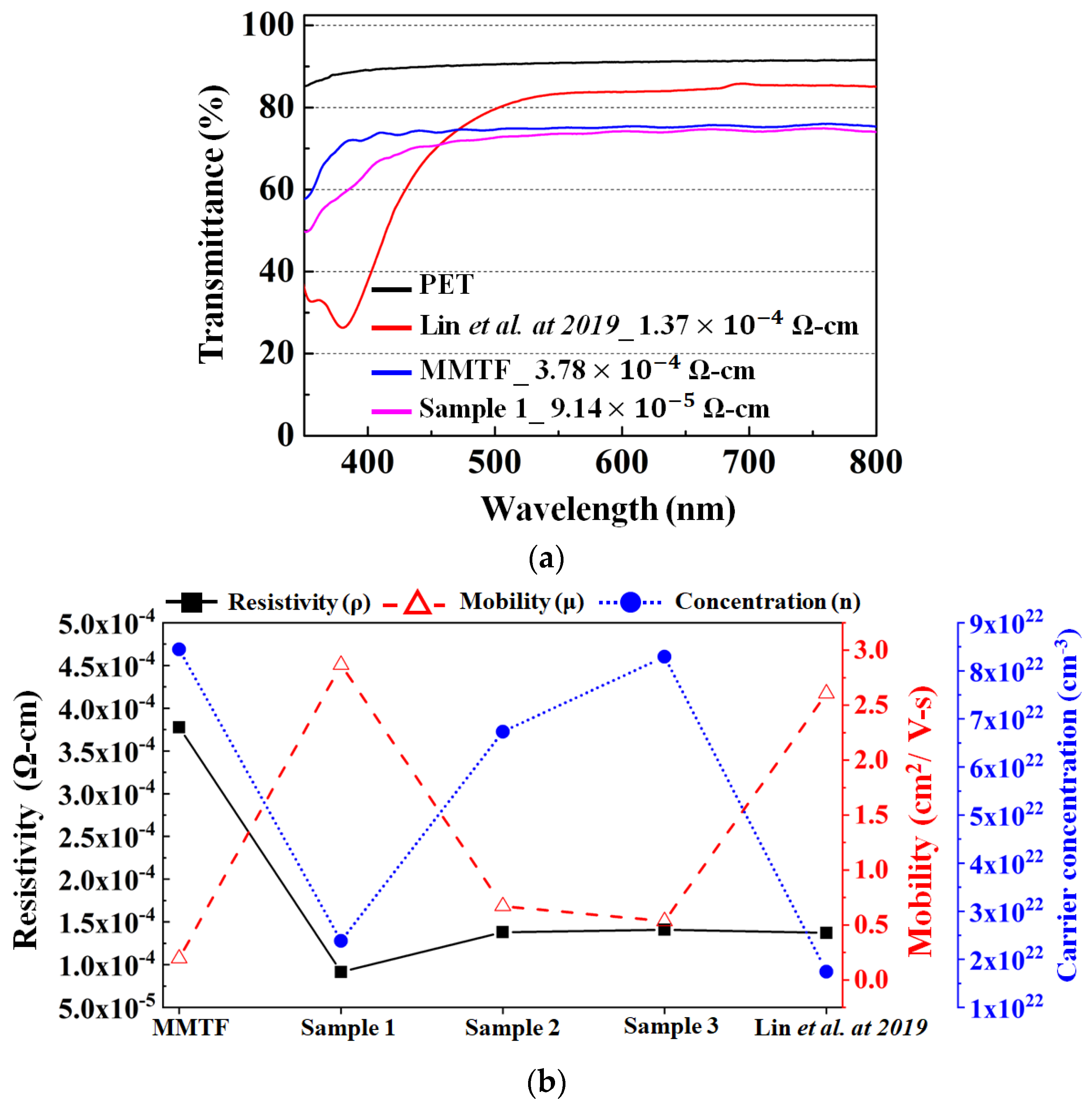
| MMTF | - | - | 25 | - | - | 3.78 × 10 −4 | 76 |
| Sample 1 | 1000 | 180 | 25 | 70 | 15 | 9.14 × 10 −5 | 31 |
| Sample 2 | 1000 | 180 | 25 | 100 | 15 | 1.38 × 10 −4 | 36 |
| Sample 3 | 1000 | 180 | 25 | 400 | 15 | 1.41 × 10 −4 | 37 |
| DUTs | Conductivity (S/m) | Relative Dielectric Constant (εr) |
|---|---|---|
| Muscle | 1.734 | 52.73 |
| Small Intestine | 3.173 | 54.88 |
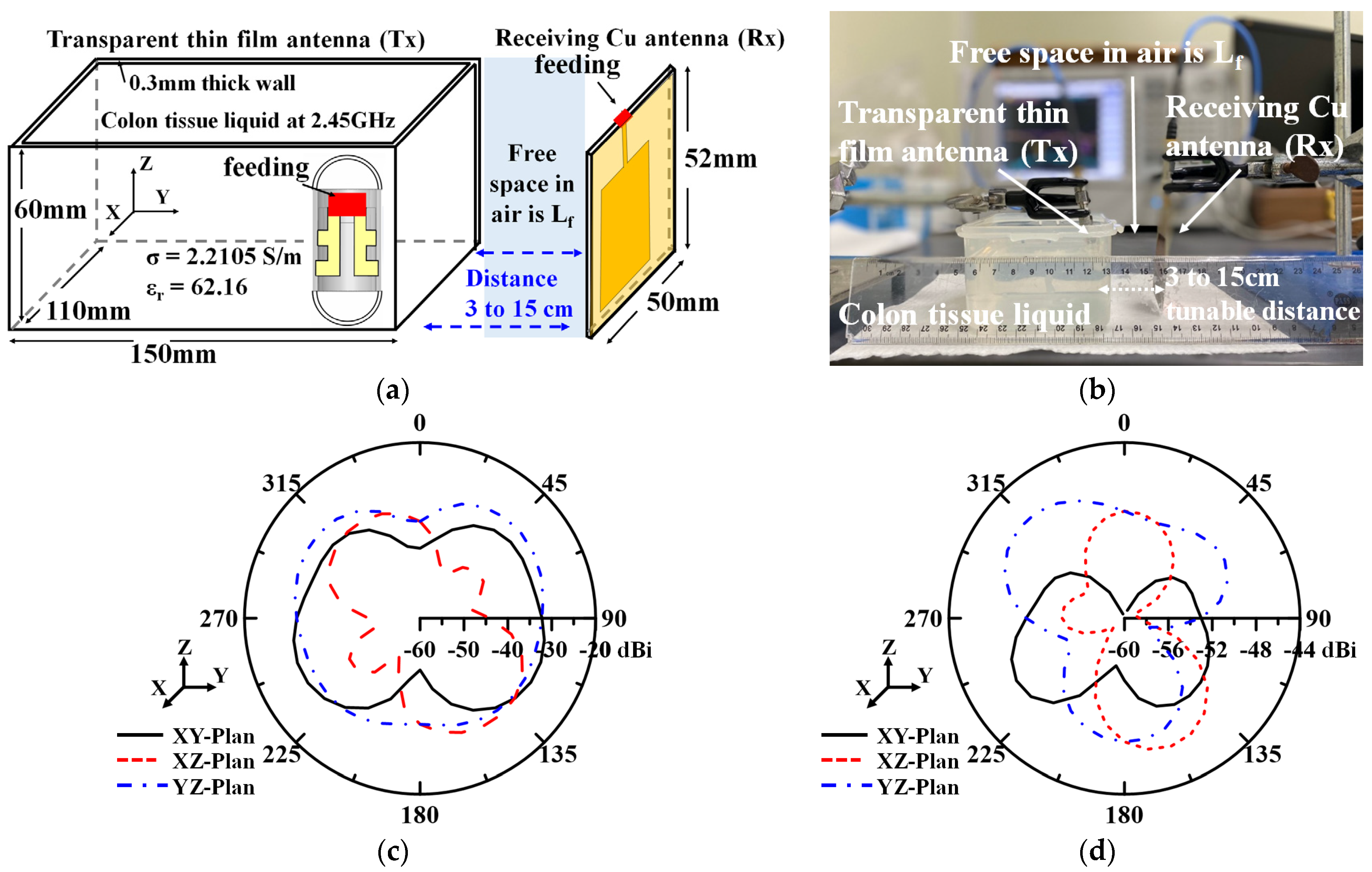
| Stomach | 2.211 | 62.16 |
| Colon | 2.038 | 53.88 |
| Ref. | Antenna Type | Dielectric Material | Frequency (GHz) | Bandwidth (MHz) | Gain (dBi) | Efficiency (%) | Transmittance (%) | Capsule Antenna Size (mm) |
|---|---|---|---|---|---|---|---|---|
| [6] | Conformal Loop | RO3010 | 0.434 | 247 | −31.8 | N/A | 0 | 11 × 26 |
| [7] | Conforma Cylinder | RO4350B | 0.915/1.4 | 948 | −0.2/1.7 | 1.14/0.09 | 0 | 11 × 22 |
| [8] | Conformal Loop | Preperm 255 | 0.433 | 795 | −35 | 0.02 | 0 | 11 × 27 |
| [10] | Conformal Loop | PET | 0.433 | N/A | −39 | N/A | 0 | 11.2 × 30.2 |
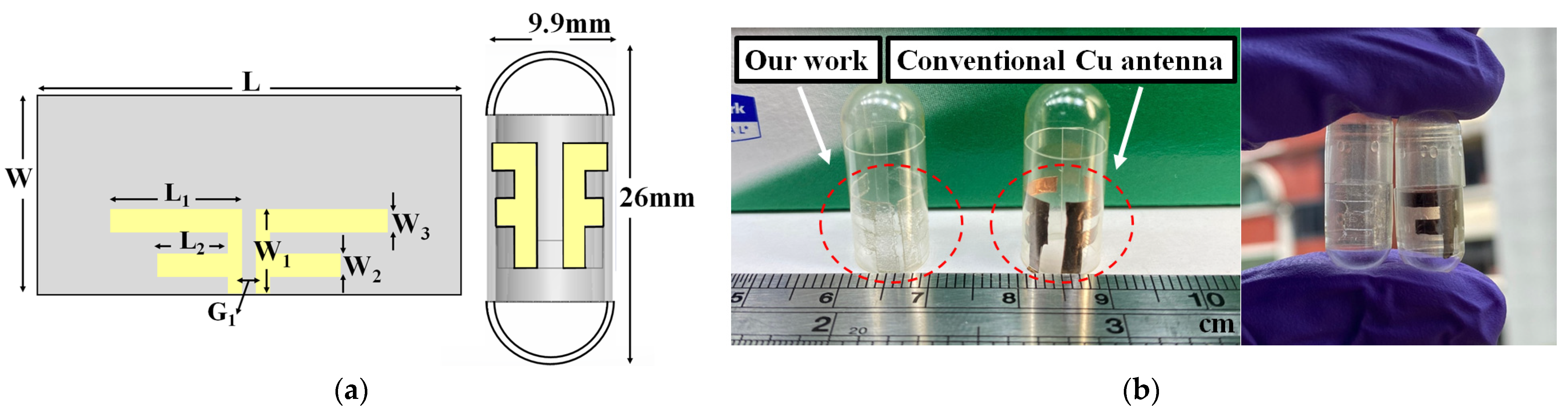
| This work | Conformal Dipole | PET | 2.45 | 855 | −26.3 | 1.04 | ≥80.3 | 9.9 × 26 |
| Transmission (Wireless Capsule System) | |||
|---|---|---|---|
| Par | Detailed | Value | |
| C | Speed of light in free space | 2.99 × 10⁸ m/s | |
| fr | Frequency (GHz) | 2.45 | |
| Pt | Transmitter power (dBm) | −40 | |
| Gt | Antenna gain (dBi) | −26.3 | |
| EIRP | Pt + Gt (dBW) | −66.3 | |
| Lf | Free space loss (dB) | 52.27 | |
| Lfeed | Feeding loss (dB) | 1.0 | |
| Receiver | |||
| Gr | Receiver antenna gain (dBi) | 2.15 | |
| T0 | Ambient temperature (K) | 293 | |
| N0 | Noise power density (dBm/Hz) | −199.95 | |
| K | Boltzmann constant | 1.38 × 10⁻²³ | |
| Signal quality | |||
| Br | Bit rate (Mb/S) | 1 or 5 | |
| Bit error | 1 × 10⁻⁵ | ||
| Eb/N0 | Ideal PSK (dB) | 9.6 | |
| Gc | Coding gain (dB) | 0 | |
| Gd | Fixing deterioration (dB) | 2.45 | |
| Margin (dB) = C/N − C/N0 | |||
| Link C/N0 (dB/Hz) | 81.03 | ||
| Required C/N0 (dB/Hz) | 42.1 or 49.09 | ||
| Margin (dB) | 31.94 or 38.93 | ||
Disclaimer/Publisher’s Note: The statements, opinions and data contained in all publications are solely those of the individual author(s) and contributor(s) and not of MDPI and/or the editor(s). MDPI and/or the editor(s) disclaim responsibility for any injury to people or property resulting from any ideas, methods, instructions or products referred to in the content. |
© 2023 by the authors. Licensee MDPI, Basel, Switzerland. This article is an open access article distributed under the terms and conditions of the Creative Commons Attribution (CC BY) license (https://creativecommons.org/licenses/by/4.0/).
Share and Cite
Lin, Y.-M.; Wu, H.-W.; Hung, C.-Y.; Chang, S.-J.; Liu, R. Dual-Polarized Transparent Antenna and Its Application for Capsule Endoscopy System. Electronics 2023, 12, 3124. https://doi.org/10.3390/electronics12143124
Lin Y-M, Wu H-W, Hung C-Y, Chang S-J, Liu R. Dual-Polarized Transparent Antenna and Its Application for Capsule Endoscopy System. Electronics. 2023; 12(14):3124. https://doi.org/10.3390/electronics12143124
Chicago/Turabian StyleLin, Yu-Ming, Hung-Wei Wu, Cheng-Yuan Hung, Shoou-Jinn Chang, and Ran Liu. 2023. "Dual-Polarized Transparent Antenna and Its Application for Capsule Endoscopy System" Electronics 12, no. 14: 3124. https://doi.org/10.3390/electronics12143124