Article

Design of a Dual-Band WiFi Antenna Using the Theory of Characteristic Modes and Nested Chinese Characters

1
School of Electrical and Information Engineering, Anhui University of Science and Technology, Huainan 232001, China
2
School of Mechanical and Electrical Engineering, Huainan Normal University, Huainan 232001, China
*
Author to whom correspondence should be addressed.
Electronics 2023, 12(16), 3465; https://doi.org/10.3390/electronics12163465
Submission received: 28 July 2023 / Revised: 13 August 2023 / Accepted: 14 August 2023 / Published: 16 August 2023

Abstract

:
In this paper, a dual-band WiFi antenna and its Multiple Input Multiple Output (MIMO) system application is designed, fabricated, and measured based on the Chinese characters “Men” and “Wei”. The antenna uses a 40 × 40 × 1.6 mm3 FR4 substrate to analyze the combinatorial structure of Chinese characters using the theory of characteristic modes, to optimize the antenna dimensions by analyzing the mode current distribution, and to broaden the antenna bandwidth by etching rectangular slots on the ground. The measured and simulated results show that the four-element MIMO antenna covers 5.68–8.01 GHz, the isolation between the antennas is higher than 20 dB in the working band, the envelope correlation coefficient and the channel capacity losses of the simulation are lower than 0.001 and 0.18 bits/s/HZ, respectively. The efficiency of the antenna is higher than 90%, and it can be used for WiFi communication bands (5.8 GHz and 6 GHz).

1. Introduction

With the proliferation of wireless devices such as smartphones, tablets and Internet of Things devices, there is an increasing demand for wireless network bandwidth and speed. However, the currently used 2.4 GHz and 5 GHz bands are already congested with limited frequency resources, resulting in limited network performance. To address this issue and meet the growing demand for wireless networks, WiFi 6 GHz (5.925–7.12 GHz) has been developed. References [1,2,3,4,5] introduced a design of a single-port antenna for 6 GHz WiFi; however, there are some limitations in the design of a single-port antenna, especially in complex wireless environments where there are still problems such as multipath effects and interference, which may lead to degradation of the signal quality and reduce the data transmission rate.
In order to further enhance the performance and coverage of 6 GHz WiFi, Multiple Input Multiple Output (MIMO) antenna technology has become a direction of great interest [6,7]. By using multiple transmitting and receiving antennas, MIMO technology can fully utilize the spatial dimension, reduce multipath interference and improve signal quality. In this way, WiFi 6 GHz can achieve higher data rates, greater capacity and more reliable wireless connections to meet the demand for low latency, high speed and stable performance. Therefore, the 6 GHz WiFi system combined with MIMO antenna technology will be expected to become an important development direction of wireless communication in the future. However, improving the isolation and reducing the radiation correlation of MIMO antennas is a challenging task. Reference [8] made the current distribution more uniform by increasing the distance between the dual ports; thus, the interference between the antennas was reduced. It is common to use parasitic elements [9,10] and defected ground structure (DGS) techniques [11,12] to improve isolation. Reference [13] proposed a dual-unit MIMO antenna that uses both parasitic element and DGS technology to achieve isolation of 15 dB. The antenna design for full-band WiFi (2.4 GHz, 5 GHz, 6 GHz) for mobile devices was described in Reference [14]. The antenna utilized L-shaped parasitic elements and a dual-branch short-circuit compensation structure to achieve coverage across multiple frequency bands. The isolation between antenna units had been ensured to be greater than 10 dB. However, in traditional methods, antenna design often depends on the experience and intuition of researchers, which will make it difficult to explain the working principle of the antenna and will take a longer time.
The theory of characteristic modes (TCM) was proposed and developed by Garbacz and Harrington [15,16] in 1968. TCM is widely used to design ultra-wideband antennas [17,18], 5G mobile phone antenna [19,20], ultra-high-frequency radio frequency identification [21,22] and array antennas [23,24]; many antennas also use characteristic modes to analyze WiFi band antennas [25,26,27,28]. TCM is preferred by many researchers for its unique analysis method, i.e., the mode significances (MS) and mode currents are analyzed to select the appropriate excitation method and the mode to be excited. Reference [25] proposed a dual-port MIMO antenna with capacitive coupling excitation determined by analyzing the position of the zero point of the electric field. The MIMO antenna proposed in Reference [26] excites three low-coupled modes simultaneously by applying inductive excitation at the current maximum, thus designing a smartwatch antenna with a low specific absorption rate and high efficiency. Reference [27] designed a high isolation four-element MIMO antenna with DGS with 30 dB isolation between antenna units. Reference [28] designed a dual-band high isolation MIMO antenna for wireless local area network (2.4 GHz and 5 GHz) applications by etching rectangular slots in the center of the microstrip to improve the radiation capability of the mode. Reference [29] designed a dual-polarized WiFi (2.4 GHz, 5.8 GHz) antenna which consists of a monopole antenna with symmetrical arms and a right short cut-off line. The antenna is linearly polarized by symmetric arms and circularly polarized by right-handed stub. References [30,31,32] introduced WiFi devices applied to mobile phones. Reference [30] utilized a double-folded monopole antenna as a radiating element at four corners of a limited substrate to achieve coverage of the WiFi (5 GHz, 6 GHz) bands. Reference [31] designed an antenna with mutually decoupled antenna pairs to achieve high isolation between the antennas using the DGS technique between the antenna pairs. Reference [32] designed a flower-shaped two-element MIMO antenna which achieves high isolation of 17.34 dB by designing the neutralization line structure. Recently, some interesting patch antenna designs, using artistic Chinese characters, have been proposed, such as: the Si character patch [33], in which the design of the Si is used as a radiation patch, while the larger metal ground plane with a certain distance from the substrate is used to improve the antenna gain; the Meng character patch [34], in which the antenna is designed with a double L-shaped feed probe and some diode switching circuits. By switching the on–off of the diode, it can cover different channels and generate circular polarization in different directions; finally, in the arranged combination of the Zhong-Guo patch [35], the patches are connected together by a feed network to form a two-element antenna array. In this paper, a single antenna model with a combination of internal and external Chinese characters is designed using TCM. Compared with the existing antenna structures in the references above, it has the characteristics of a simple structure, and the four-element MIMO antenna isolation is greater than 20 dB; in the WiFi band (5.8 GHz, 6 GHz), the antenna gain can reach 6.5 dBi and the efficiency can reach 93%.
In summary, this paper will be divided as follows: in Section 2, the overall structure of the four-element MIMO antenna is first introduced, followed by the design and analysis of the single antenna using the characteristic mode. Moreover, this section describes the design and analysis process of the MIMO antenna. Section 3 presents some parametric analysis. Section 4 gives the measured antenna system performance, such as the S-parameters and the radiation pattern values. Finally, some conclusions and future work ideas are given in Section 5.

2. Design and Analysis of the Antenna

Figure 1 illustrates the final antenna consisting of a central isolation branch placed on the upper surface of the substrate, and four identical “Men (门)” and “Wei (卫)” structures rotating around the center point. The rectangular ground on the lower surface of the FR4 substrate (εr = 4.4, tan δ = 0.02) represents a cross of the Chinese character “Wei”, whereas the rest is located on the upper surface of the substrate; moreover, the Chinese character “Men” is located on the upper surface of the substrate and encloses “Wei”. Firstly, the distribution of the resonant mode currents is derived by performing the characteristic mode analysis of the combined structure of the individual Chinese characters using Computer Simulation Technology (CST) software. The mode currents are then analyzed to determine the feeding method and they are slotted in the ground to extend the bandwidth of the antenna; therefore, the performance and frequency response of the antenna would improve. Then, the High-Frequency Structure Simulator (HFSS) software is used to construct a four-element MIMO antenna through a rotational replication operation for a single antenna. Finally, isolation branches are added to enhance the antenna isolation. The sizes of the antenna are provided in Table 1.

2.1. Design and Analysis of a Single Antenna Base on the TCM

Figure 2 shows the evolution of the antenna structure of one unit where the antenna uses an FR4 substrate of size 40 × 40 × 1.6 mm3. The modeling and characteristic mode analysis of the initial structure of the antenna, using the commercial CST software, is represented in Figure 2a.
The characteristic mode tells us that the intensity of excitation for mode J n is determined by the modal weighting coefficient α n , which can be expressed as:
α n = V n i 1 + j λ n
where λ n is the eigenvalue and V n i is the modal excitation coefficient, defined as:
V n i = J n , E i = S J n · E i d s
where E i is the external source. For a particular pattern, the eigenvalues are fixed, so α n is completely dependent on V n i .
In the TCM, MS and characteristic angle (CA) are important parameters, and can be calculated using this equation:
MS = 1 / ( 1 + j λ n )
CA = π tan 1 ( λ n )
When the MS value is greater than 0.707, the antenna is operating in a potentially excitable resonant mode [36]; however, when MS is close to zero, the mode is difficult to excite. When considering MS, CA also needs to be considered, and when CA is close to 180°, it indicates that the mode is prone to resonance [37]. The MS and CA comparison plots before and after the evolution of the first three modes are given in Figure 3. According to the MS and CA curves of model I in Figure 3, the resonance frequencies of the initial structure are 4.035 GHz, 5.965 GHz and 7.015 GHz, respectively.
As for Figure 4, it shows the current distribution in the resonant mode. The currents of Mode 1 are mainly located on the feeder, the ground, and the right branch of the “Men”, whereas the Mode 2 current is mainly concentrated in the feeder and the Mode 3 currents are mainly located on the ground and in the upper right corner of the radiator. Feeding two separate modes to increase the bandwidth is not always possible due to the ideal feed types, locations, and impedances that can be very different from each other [38]; thus, it can be derived from the resonant mode currents that Mode 1 and Mode 2 are more likely to be fed using the same excitation.
The primary focus of this paper revolves around the WiFi band, mainly centered on optimizing Mode 2. By analyzing the current distribution of Mode 2, it was observed that the current on the ground plane exhibited relatively weaker intensity. To alter the current strength and optimize the microstrip antenna structure, a slotting technique was applied in this research. Specifically, rectangular slots were etched at the positions where the ground plane current was minimal. The current distribution of Mode 2 after slotting is depicted in Figure 4e. It is evident from Figure 4 that slotting enhances the current on the ground plane. Furthermore, compared to the initial structure, it is observed from Figure 3 that Mode 2 has a wider mode bandwidth after slotting, thereby enhancing its radiation capability [28].
The antenna is fed by a 50 Ω microstrip feed line. The S-parameters and the gain of the single-port antenna simulation are shown in Figure 5. The antenna covers the frequency range of 5.67–7.99 GHz and can cover the WiFi range (5.8 GHz, 6 GHz); as for the gain of the working band, it is in the range 2.24–2.81 dBi. In addition, Figure 5 also shows a comparison of the S-parameters before and after the slotted ground where, after etching the rectangular slot, not only the bandwidth is increased, but also the matching performance is better. This confirms that expanding the coverage of the MS can improve the bandwidth of the antenna.

2.2. MIMO Antenna Design and Analysis
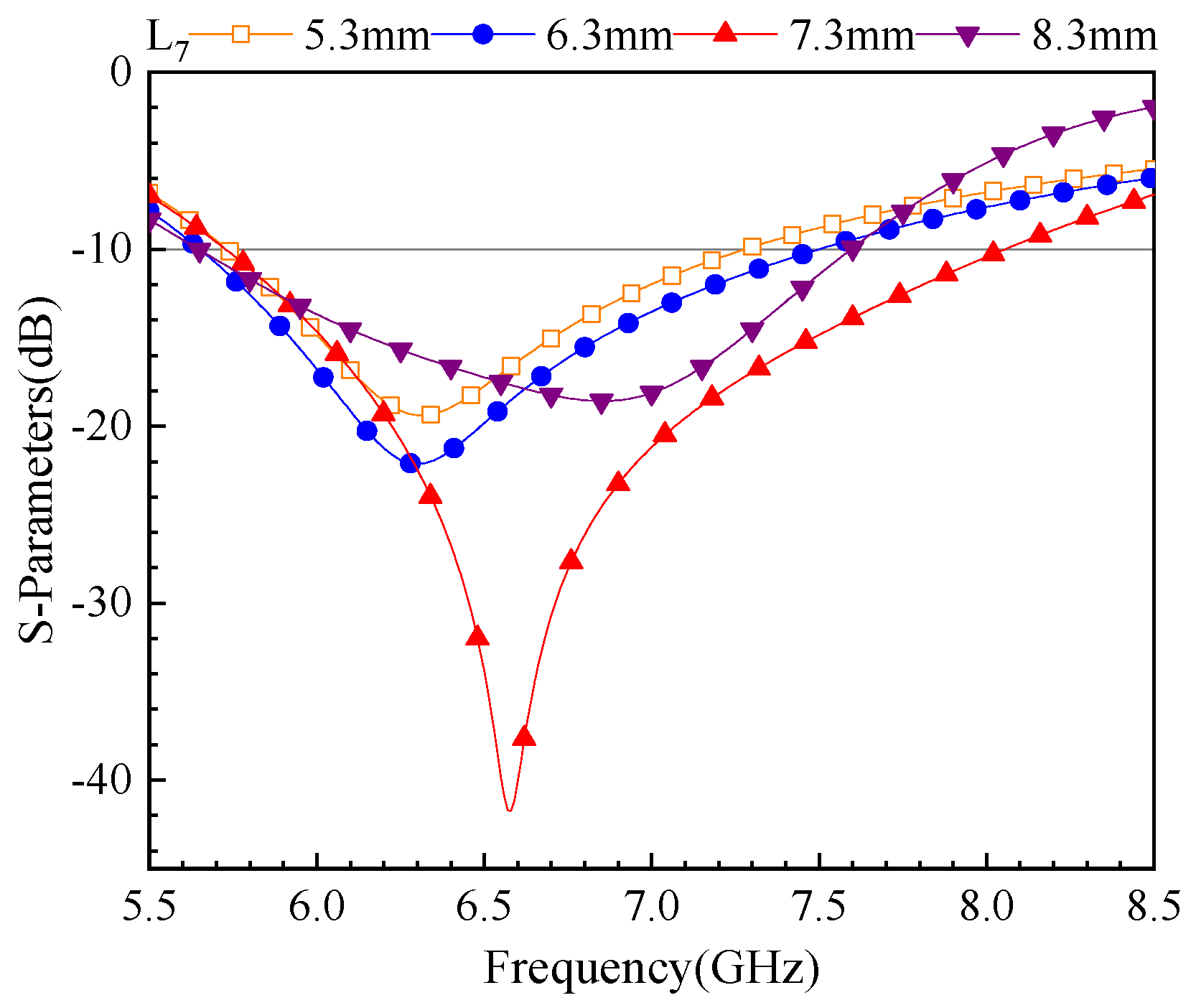
Referring to Figure 6a, the designed single antenna rotates around the center point to form a four-element MIMO antenna called Model III. As for Figure 6b, to further reduce the coupling between antennas, an isolated branch is designed in this paper where the MIMO antenna is called Model IV. Moreover, the isolated branch is composed of a diamond ring, a rectangle leading from each diamond corner, and a z-shape attached to the rectangle. Finally, Figure 7 shows a prototype MIMO antenna fabricated using the tin spraying process. The fabrication process starts with copper cladding on the metal radiator area of the FR4 substrate, and then the tin is sprayed on the copper clad area, which facilitates the soldering of the subminiature version A connector. Due to the limitations of the factory’s fabrication process and the tiny burrs generated during the soldering process, the antenna is subject to a certain degree of error in actual testing and simulation. In order to ensure the accuracy of the test, we chose a substrate manufacturer with smaller fabrication errors and treated the burrs on the soldering surface. The relevant parameters of the branch are shown in Table 1.
Figure 8 shows the comparison of the S-parameters before and after adding the isolation branches, and the current distribution on the antenna surface is presented in Figure 9. From S11, the antenna coverage frequency is expanded from 5.7–7.84 GHz to 5.61–8.18 GHz, but it was found that the frequency was shifted before the isolated branches were added. This was mainly due to the rotation and replication process of the antenna radiating body that will introduce certain interference and mismatch, resulting in the alteration of the antenna performance. Concerning S12 and S13, before the inclusion of the isolation branches, S12 and S13 achieved 18 dB and 20 dB, respectively, and it can be noticed from Figure 9a that the MEN branches have isolated a large portion of the current. After adding the isolation branch, the simulated S12 and S13 achieved 21 dB. Furthermore, the added isolation branches not only improve the isolation degree and reduce the crosstalk, but they also generate new high-frequency resonance to expand the high-frequency bandwidth and improve the signal transmission performance and spectral utilization efficiency. At 6.06 GHz and 7.48 GHz frequencies, when port 1 is excited and the other ports are cut off with a matching load of 50 Ω, the isolation branch further blocks most of the current; thus the coupling is reduced and the isolation of the MIMO antenna is improved.

3. Parametric Study

To examine the effect of different parameters of antenna on its performance, a systematic study is carried out. The goal of this study is to identify the fabrication tolerance, and more importantly, to pinpoint the effects of antenna parameters on the bandwidth. We investigated the effects of ground slot length L7, gap width and isolation branch length L8 on antenna performance. The first two parameters are selected because they establish the framework of a single antenna structure, while the last parameter plays an important role in improving the isolation of MIMO antenna systems.
As shown in Figure 10, the width of the gap affects the coupling degree between the Wei patch and the Men patch. When gap = 0.2 mm, the performance of the S parameter is the best. As the gap increases, there is a certain performance decrease in both bandwidth and matching degree of the antenna, which becomes more obvious with the increase of distance. Smaller gaps can enhance the coupling between them and consequently improve the performance of the antenna. When the gap increases, the electromagnetic coupling is weakened, leading to a decrease in the bandwidth and matching of the antenna. As shown in Figure 11, the ground slotting has a certain influence on the bandwidth of the antenna, which shows that when L7 increases from 5.3 mm to 7.3 mm in length, the bandwidth of the antenna widens with the increase in length and the better match, but when it continues to increase to 8.3 mm, the bandwidth of the antenna decreases close to 1 GHz. This may be because when the slotting length exceeds a certain threshold, the introduced structural changes cause the resonant frequency of the antenna to deviate from expected, resulting in the bandwidth of the antenna being limited and the signal not being transmitted to a higher frequency range.
The isolation branch of the MIMO antenna plays a crucial role in the isolation degree of the antenna, as shown in Figure 12, when the length of the branch L8 is 8 mm and the S11 parameter of the antenna is higher than −10 dB, which may be caused by the mismatch between the length of the isolation branch and the operating frequency range of the antenna element, thus causing an impedance mismatch and reducing the performance of the antenna. As the length increases, the S parameter of the antenna tends to be stable, and the isolation of the antenna further decreases to below −20 dB.

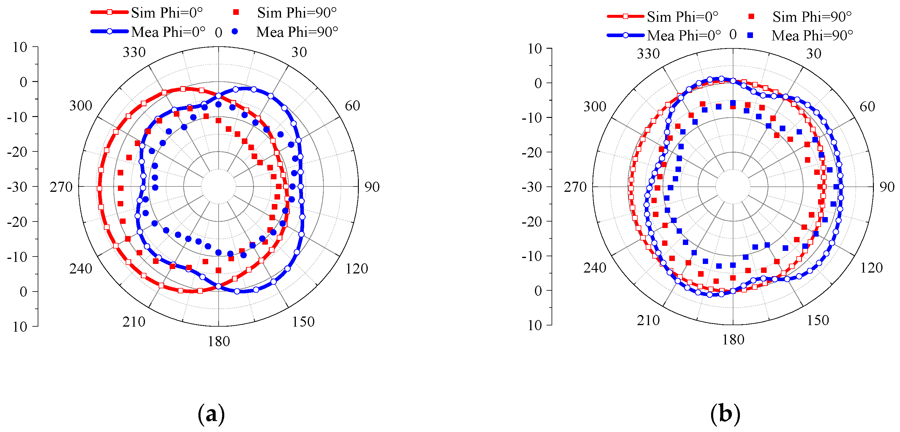
4. Measurement and Simulation Results

The S-parameters are measured using an AV3629D vector network analyzer and Figure 13 shows the far-field measured environment. Figure 14 shows the simulated and measured S-parameters results. These findings show that the antenna can cover the bandwidth range 5.68–8.01 GHz, with an isolation degree of 20 dB. However, there are differences between the simulated and the measured results, which may be due to soldering errors and manufacturing tolerances.
Furthermore, the antenna was tested for its radiation patterns in an anechoic chamber. Because the four antenna elements are identical, only the radiation pattern of Ant-1 was measured, and the rest of the ports were replaced by a 50 Ω load matching. The radiation direction diagram of the antenna was tested in the anechoic chamber, as presented in Figure 15, which shows the simulated and measured EH plane direction maps in the resonant mode at 6.06 GHz and 7.48 GHz, respectively. The simulated and measured results are matching. Moreover, Figure 16 shows the peak gain and the antenna efficiency for the proposed MIMO system where the antenna gains ranges between 2.5 and 6.5 dBi and the MIMO antenna efficiency varies between 79% and 93%. Furthermore, the gain in the WiFi band varies between 4.73 and 6.5 dBi and its efficiency is in the range of 90–93%.
The degree of the channel isolation of a MIMO antenna can be measured by the envelope correlation coefficient (ECC) technique, where a lower ECC indicates a higher pattern diversity of the antenna. The ECC data is calculated using the S-parameters through (5) [39]. Diversity gain (DG) is an important measure of how much the signal is amplified or attenuated in a MIMO system. It can be expressed by the ECC as Equation (6). In general, The ECC of the MIMO antenna is generally lower than 0.5, which is considered to comply with the requirements; the closer the DG is to 10, the better the performance of the MIMO antenna. Figure 17 shows the simulated ECC and DG of the proposed MIMO system, and the results show that the proposed four-element MIMO antenna system has both a larger DG and a smaller ECC. The ECC of the studied and designed antenna in this paper is lower than 0.001 in the WiFi band.
E C C = S i i * S i j + S j i * S j j 2 1 S i i 2 S j i 2 1 S j j 2 S i j 2
D G = 10 × 1 E C C 2
In addition, the total active reflection coefficient (TARC) and the channel capacity losses (CCL) are investigated in this paper. The TARC value falls within the range of 0 to 1, wherein a value nearing 0 signifies minimal reflection power and a value nearing 1 signifies significant reflection power. The proximity of the TARC value to 0 indicates superior system performance because it implies the efficient transmission of energy to the receiving end, minimizing reflection or loss. CCL is also an important parameter to measure the MIMO antenna system; usually, when the CCL is lower than 0.4 bits/s/Hz, the MIMO antenna system is considered to have met its performance requirements. These parameters are computed using Equations (7)–(9), given below [40,41,42]. Figure 18 shows the TARC and the CCL calculations for the proposed MIMO antenna, which shows that the TARC is below 30 dB, and the CCL is below 0.18 bits/s/HZ in the operating band. This fully reflects the high-performance characteristics of the MIMO antenna system.
T A R C = ( S 11 + S 12 e j θ ) 2 + ( S 21 + S 22 e j θ ) 2 2
C C L = log 2 det ( α R ) α R = α 11 α 12 α 21 α 22
α 11 = 1 ( S 11 2 + S 12 2 ) ;   α 12 = S 11 * S 12 S 21 * S 22 α 22 = 1 ( S 22 2 + S 21 2 ) ;   α 21 = S 22 * S 21 S 12 * S 11
Finally, Table 2 shows the dimensions, the operating band, peak gain, the isolation, the efficiency and the ECC of the proposed antenna, which are compared with some previously reported WiFi antennas. The antenna proposed in this paper using the characteristic mode theory uses inexpensive and easily processed FR4 substrate as the dielectric, and its size is only 40 × 40 × 1.6 mm3, which is smaller than the size of the proposed antenna. The proposed four-element MIMO antenna system achieves an isolation of 20 dB in the frequency band, with an efficiency of up to 93% and a maximum peak gain of 6.5 dBi. Furthermore, it exhibits an ECC metric of less than 0.001. It is clear that the proposed design is very compact and performs well.

5. Conclusions

In this paper, the design of the “Men Wei” antenna, based on the characteristic mode theory and its MIMO system application, is proposed. The antenna’s size is 40 × 40 × 1.6 mm3, and the commonly used FR4 substrate is used, which is characterized by its easy processing and low cost. As for the simulated and measured results, they show that the antenna and MIMO system have versatility and better performance, exhibiting excellent miniaturization, high isolation, low envelope correlation coefficients, lower TARC and CCL, which helps to enhance the performance and user experience of WiFi devices. The antenna is suitable for the 5.8 GHz and 6 GHz bands of WiFi devices.

Author Contributions

Conceptualization, Z.W.; methodology, M.W.; Simulation, M.W.; validation, M.W. and W.N.; writing—review and editing, Z.W. and M.W.; data curation, W.N. All authors have read and agreed to the published version of the manuscript.

Funding

This research was funded by the Anhui Provincial Natural Science Foundation of China under Grant no. 2108085MF200, in part by the Natural Science Foundation of Anhui Provincial Education Department under Grant no. 2022AH051583, in part by the Anhui Province Graduate Academic Innovation Project under grant no. 2021200851.

Data Availability Statement

The simulated and measured data used to support the findings of this study are included within the article.

Conflicts of Interest

The authors declare no conflict of interest.

References

  1. Nguyen, T.D.; Lee, Y.; Jung, C.W. Transparent and Flexible Patch Antenna Using MMF for Conformal WiFi-6E Applications. J. Electromagn. Eng. Sci. 2023, 23, 310–317. [Google Scholar] [CrossRef]
  2. Jhang, W.-C.; Sun, J.-S. Small Antenna Design of Triple Band for WIFI 6E and WLAN Applications in the Narrow Border Laptop Computer. Int. J. Antennas Propag. 2021, 2021, 7334206. [Google Scholar] [CrossRef]
  3. Paul, L.C.; Saha, H.K.; Rani, T.; Azim, R.; Islam, M.T.; Samsuzzaman, M. A dual-band semi-circular patch antenna for WiMAX and WiFi-5/6 applications. Int. J. Commun. Syst. 2023, 36, e5357. [Google Scholar] [CrossRef]
  4. Liu, X.; Wang, H.; Yang, X.; Wang, J. Quad-Band Circular Polarized Antenna for GNSS, 5G and WIFI-6E Applications. Electronics 2022, 11, 1133. [Google Scholar] [CrossRef]
  5. Paul, L.C.; Ali, H.; Rani, T.; Saha, H.K.; Jim, T.R. A sixteen-element dual band compact array antenna for ISM/Bluetooth/Zigbee/WiMAX/WiFi-2.4/5/6 GHz applications. Heliyon 2022, 8, e11675. [Google Scholar] [CrossRef] [PubMed]
  6. Wong, K.L.; Jiang, H.Y.; Li, W.Y. Decoupling Hybrid Metal Walls and Half-Wavelength Diagonal Open-Slots Based Four-Port Square Patch Antenna with High Port Isolation and Low Radiation Correlation for 2.4/5/6 GHz WiFi-6E 4 × 4 MIMO Access Points. IEEE Access 2022, 10, 81296–81308. [Google Scholar] [CrossRef]
  7. Yang, Q.; Zhang, C.; Cai, Q.; Loh, T.H.; Liu, G. A MIMO Antenna with High Gain and Enhanced Isolation for WLAN Applications. Appl. Sci. 2022, 12, 2279. [Google Scholar] [CrossRef]
  8. Jeong, G.-T.; Choi, S.; Lee, K.-H.; Kim, W.-S. Low-Profile Dual-Wideband MIMO Antenna with Low ECC for LTE and Wi-Fi Applications. Int. J. Antennas Propag. 2014, 2014, 158028. [Google Scholar] [CrossRef]
  9. Sharma, V.; Goel, A.; Upadhayay, M.D.; Singh, A.V. A Pi-Shaped Slot Antenna for 5.2 GHz WLANMIMO Application. IETE J. Res. 2023, 69, 1613–1625. [Google Scholar] [CrossRef]
  10. Paiva, S.B.; Junior, A.G.D.; Neto, V.P.S.; D’Assunção, A.G. A New Compact Dual-Polarized MIMO Antenna Using Slot and Parasitic Element Decoupling for 5G and WLAN Applications. Electronics 2022, 11, 1943. [Google Scholar] [CrossRef]
  11. Nakmouche, M.F.; Deslandes, D.; Gagnon, G. Dual-Band 4-Port H-DGS Based Textile MIMO Antenna Design Using Genetics Algorithms for Wearable Application. In Proceedings of the 2022 IEEE International Symposium on Antennas and Propagation and USNC-URSI Radio Science Meeting (AP-S/URSI), Denver, CO, USA, 10–15 July 2022; pp. 1182–1183. [Google Scholar]
  12. Malaisamy, K.; Santhi, M.; Robinson, S. Design and analysis of 4 × 4 MIMO antenna with DGS for WLAN applications. Int. J. Microw. Wirel. Technol. 2021, 13, 979–985. [Google Scholar] [CrossRef]
  13. Peng, H.; Zhi, R.; Yang, Q.; Cai, J.; Wan, Y.; Liu, G. Design of a MIMO Antenna with High Gain and Enhanced Isolation for WLAN Applications. Electronics 2021, 10, 1659. [Google Scholar] [CrossRef]
  14. Cai, C.-A.; Kai, K.-Y.; Liao, W.-J. A WLAN/WiFi-6E MIMO Antenna Design for Handset Devices. In Proceedings of the 2021 International Symposium on Antennas and Propagation (ISAP), Taipei, Taiwan, 19–22 October 2021; pp. 1–2. [Google Scholar]
  15. Garbacz, R.; Turpin, R. A generalized expansion for radiated and scattered fields. IEEE Trans. Antennas Propag. 1971, 19, 348–358. [Google Scholar] [CrossRef]
  16. Harrington, R.; Mautz, J. Theory of characteristic modes for conducting bodies. IEEE Trans. Antennas Propag. 1971, 19, 622–628. [Google Scholar] [CrossRef]
  17. Zhang, Q.; Ma, R.; Su, W.; Gao, Y. Design of a Multimode UWB Antenna Using Characteristic Mode Analysis. IEEE Trans. Antennas Propag. 2018, 66, 3712–3717. [Google Scholar] [CrossRef]
  18. Zhao, X.; Yeo, S.P.; Ong, L.C. Planar UWB MIMO Antenna with Pattern Diversity and Isolation Improvement for Mobile Platform Based on the Theory of Characteristic Modes. IEEE Trans. Antennas Propag. 2018, 66, 420–425. [Google Scholar] [CrossRef]
  19. Zhang, H.H.; Yu, G.G.; Liu, X.Z.; Cheng, G.S.; Xu, Y.X.; Liu, Y.; Shi, G.M. Low-SAR MIMO Antenna Array Design Using Characteristic Modes for 5G Mobile Phones. IEEE Trans. Antennas Propag. 2022, 70, 3052–3057. [Google Scholar] [CrossRef]
  20. Zhang, H.H.; Liu, X.Z.; Cheng, G.S.; Liu, Y.; Shi, G.M.; Li, K. Low-SAR Four-Antenna MIMO Array for 5G Mobile Phones Based on the Theory of Characteristic Modes of Composite PEC-Lossy Dielectric Structures. IEEE Trans. Antennas Propag. 2022, 70, 1623–1631. [Google Scholar] [CrossRef]
  21. Sharif, A.; Ouyang, J.; Yang, F.; Chattha, H.T.; Imran, M.A.; Alomainy, A.; Abbasi, Q.H. Low-Cost Inkjet-Printed UHF RFID Tag-Based System for Internet of Things Applications Using Characteristic Modes. IEEE Internet Things J. 2019, 6, 3962–3975. [Google Scholar] [CrossRef]
  22. Sharif, A.; Ouyang, J.; Raza, A.; Hussain, S.; Nasir, M.; Arshad, K.; Assaleh, K.; Ramzan, N.; Imran, M.A.; Abbasi, Q.H. UHF RFID Tag Design Using Theory of Characteristics Modes for Platform-Tolerant and Harsh Metallic Environments. IEEE J. Radio Freq. Identif. 2022, 6, 524–533. [Google Scholar] [CrossRef]
  23. Jha, K.R.; Rana, N.; Sharma, S.K. Design of Compact Antenna Array for MIMO Implementation Using Characteristic Mode Analysis for 5G NR and Wi-Fi 6 Applications. IEEE Open J. Antennas Propag. 2023, 4, 262–277. [Google Scholar] [CrossRef]
  24. Liu, W.; Yan, S. A Design of Millimeter-Wave Dual-Polarized SIW Phased Array Antenna Using Characteristic Mode Analysis. IEEE Antennas Wirel. Propag. Lett. 2022, 21, 29–33. [Google Scholar] [CrossRef]
  25. Wen, D.; Hao, Y.; Wang, H.; Zhou, H. Design of a MIMO Antenna with High Isolation for Smartwatch Applications Using the Theory of Characteristic Modes. IEEE Trans. Antennas Propag. 2019, 67, 1437–1447. [Google Scholar] [CrossRef]
  26. Zhang, H.H.; Gong, L.F.; Liu, X.Z.; Xu, Y.X.; Cheng, G.S.; Liu, Y.; Shi, G.M.; Zheng, C.; Han, Y.J. Design of Low-SAR and High On-Body Efficiency Tri-Band Smartwatch Antenna Utilizing the Theory of Characteristic Modes of Composite PEC-Lossy Dielectric Structures. IEEE Trans. Antennas Propag. 2023, 71, 1913–1918. [Google Scholar] [CrossRef]
  27. Andrade, E.F.; Miguel, A.P.; Villanueva, R.G.; Aguilar, H.J. Characteristic mode analysis applied to reduce the mutual coupling of a four-element patch MIMO antenna using a defected ground structure. IET Microw. Antennas Propag. 2020, 14, 215–226. [Google Scholar] [CrossRef]
  28. Zhang, W.; Li, Y.; Wei, K.; Zhang, Z. A Dual-Band MIMO Antenna System for 2.4/5 GHz WLAN Applications. IEEE Trans. Antennas Propag. 2023, 71, 5749–5758. [Google Scholar] [CrossRef]
  29. Mohanty, A.; Behera, B.R. CMA assisted 4-port compact MIMO antenna with dual-polarization characteristics. AEU—Int. J. Electron. Commun. 2021, 137, 153794. [Google Scholar] [CrossRef]
  30. Mathur, P.; Augustine, R.; Gopikrishna, M.; Raman, S. Dual MIMO Antenna System for 5G Mobile Phones, 5.2 GHz WLAN, 5.5 GHz WiMAX and 5.8/6 GHz WiFi Applications. IEEE Access 2021, 9, 106734–106742. [Google Scholar] [CrossRef]
  31. Du, K.; Wang, Y.; Zhang, L.; Hu, Y. Design of Wideband Decoupling Antenna Pairs for 5G Portable Devices at N77/N78/N79 Bands. Micromachines 2022, 13, 1964. [Google Scholar] [CrossRef]
  32. Babu, K.V.; Das, S.; Ali, S.S.; el Ghzaoui, M. Broadband sub-6 GHz flower-shaped MIMO antenna with high isolation using theory of characteristic mode analysis (TCMA) for 5G NR bands and WLAN applications. Int. J. Commun. Syst. 2023, 36, e5442. [Google Scholar] [CrossRef]
  33. Zhou, W.; Yue, C.; Li, Y.; Xia, Y.; Qiu, B.; Chung, K.L. A High Gain Si-shaped Circularly Polarized Patch Antenna for 5G Application. In Proceedings of the 2021 IEEE 4th International Conference on Electronic Information and Communication Technology (ICEICT), Xi’an, China, 18–20 August 2021; pp. 284–285. [Google Scholar]
  34. Chung, K.L.; Xie, S.; Li, Y.; Liu, R.; Ji, S.; Zhang, C. A Circular-Polarization Reconfigurable Meng-Shaped Patch Antenna. IEEE Access 2018, 6, 51419–51428. [Google Scholar] [CrossRef]
  35. Chung, K.L.; Li, W.; Li, Y.; Liu, R.; Zhang, P. Chinese Character-Shaped Artistic Patch Antenna. IEEE Antennas Wirel. Propag. Lett. 2019, 18, 1542–1546. [Google Scholar] [CrossRef]
  36. Wang, C.; Chen, Y.; Yang, S. Bandwidth Enhancement of a Dual-Polarized Slot Antenna Using Characteristic Modes. IEEE Antennas Wirel. Propag. Lett. 2018, 17, 988–992. [Google Scholar] [CrossRef]
  37. Zeng, J.; Liang, X.; He, L.; Guan, F.; Lin, F.H.; Zi, J. Single-Fed Triple-Mode Wideband Circularly Polarized Microstrip Antennas Using Characteristic Mode Analysis. IEEE Trans. Antennas Propag. 2022, 70, 846–855. [Google Scholar] [CrossRef]
  38. Miers, Z.; Li, H.; Lau, B.K. Design of Bandwidth-Enhanced and Multiband MIMO Antennas Using Characteristic Modes. IEEE Antennas Wirel. Propag. Lett. 2013, 12, 1696–1699. [Google Scholar] [CrossRef]
  39. Liu, Y.Y.; Tu, Z.H. Compact Differential Band-Notched Stepped-Slot UWB-MIMO Antenna with Common-Mode Suppression. IEEE Antennas Wirel. Propag. Lett. 2017, 16, 593–596. [Google Scholar] [CrossRef]
  40. Addepalli, T.; Kumar, M.S.; Jetti, C.R.; Gollamudi, N.K.; Kumar, B.K.; Kulkarni, J. Fractal Loaded, Novel, and Compact Two- and Eight-Element High Diversity MIMO Antenna for 5G Sub-6 GHz (N77/N78 and N79) and WLAN Applications, Verified with TCM Analysis. Electronics 2023, 12, 952. [Google Scholar] [CrossRef]
  41. Bayarzaya, B.; Hussain, N.; Awan, W.A.; Sufian, M.A.; Abbas, A.; Choi, D.; Lee, J.; Kim, N. A Compact MIMO Antenna with Improved Isolation for ISM, Sub-6 GHz, and WLAN Application. Micromachines 2022, 13, 1355. [Google Scholar] [CrossRef]
  42. Khan, I.; Wu, Q.; Ullah, I.; Rahman, S.U.; Ullah, H.; Zhang, K. Designed Circularly Polarized Two-Port Microstrip MIMO Antenna for WLAN Applications. Sciences 2022, 12, 1068. [Google Scholar] [CrossRef]
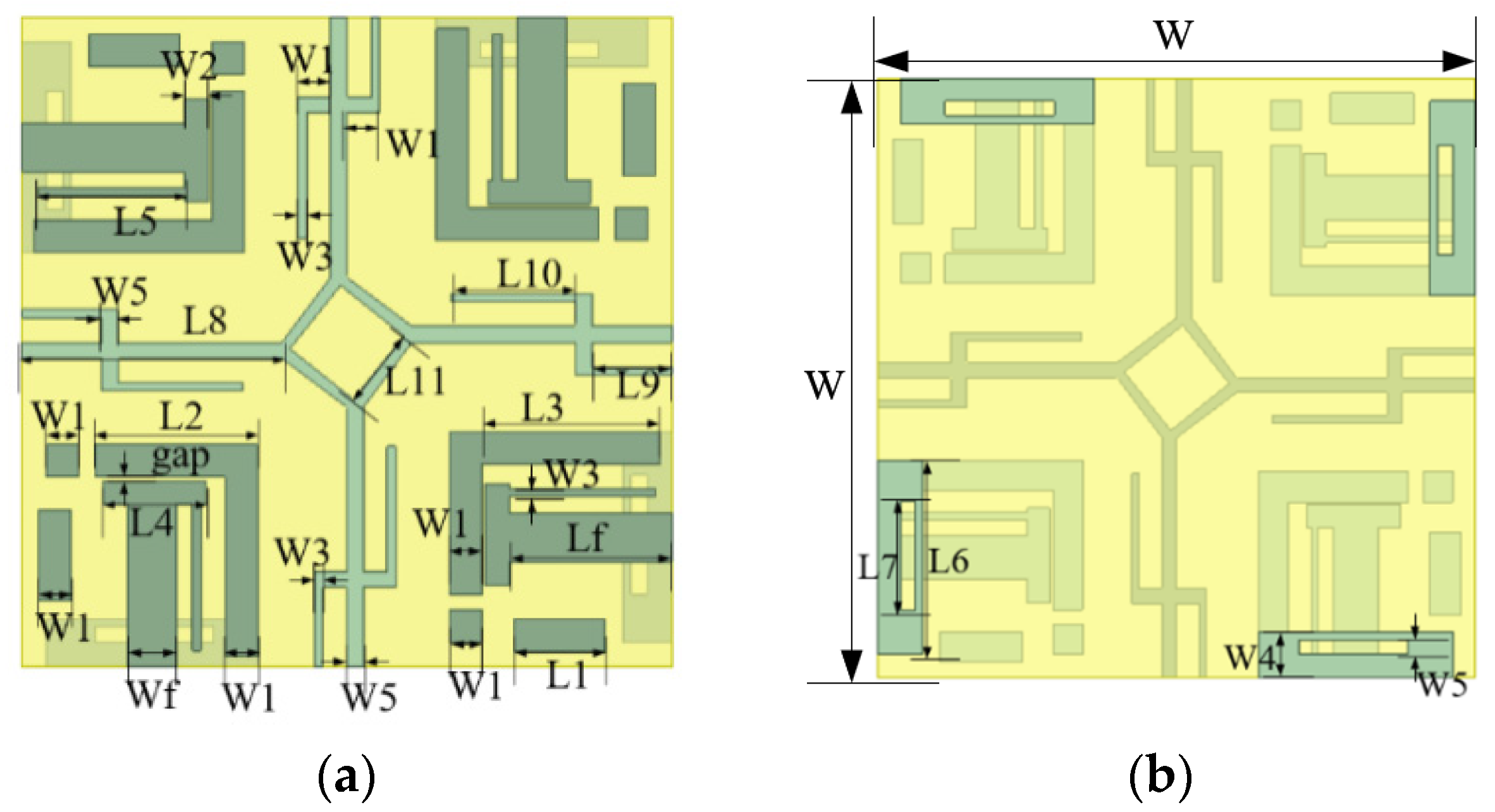
Figure 1. Geometry and parameters of the proposed MIMO antenna: (a) front view, (b) back view.
Electronics 12 03465 g001
Figure 2. The evolution of the antenna: (a) model I-Original structure, (b) model II-Final single antenna structure.
Electronics 12 03465 g002
Figure 3. MS and CA for the first three modes: (a) MS, (b) CA.
Electronics 12 03465 g003
Figure 4. Model I and model II currents at resonant mode where, for model I: (a) Mode 1 at 4.035 GHz, (b) Mode 2 at 5.965 GHz, (c) Mode 3 at 7.015 GHz; for model II: (d) Mode 1 at 4.535 GHz, (e) Mode 2 at 6.35 GHz, (f) Mode 3 at 8.385 GHz.
Electronics 12 03465 g004
Figure 5. Simulated single antenna S-parameters and gain.
Electronics 12 03465 g005
Figure 6. Design of MIMO antennas: (a) model III, (b) model IV.
Electronics 12 03465 g006
Figure 7. Fabrication prototype of the proposed four-port MIMO antenna.
Electronics 12 03465 g007
Figure 8. Effect of isolated branch on S-parameters, (a) S11–S44, (b) S12 and S13.
Electronics 12 03465 g008
Figure 9. Surface current distribution of (a) model III at 6.6 GHz, (b) model IV at 6.06 GHz, (c) model IV at 7.48 GHz.
Electronics 12 03465 g009
Figure 10. Effect of gap on S-parameters.
Electronics 12 03465 g010
Figure 11. Effect of slotted length L7 on S-parameters.
Electronics 12 03465 g011
Figure 12. Effect of isolated branch length L8 on S-parameters: (a) S11; (b) S12.
Electronics 12 03465 g012
Figure 13. The environment of the model measurement.
Electronics 12 03465 g013
Figure 14. S-parameters of proposed MIMO antenna.
Electronics 12 03465 g014
Figure 15. Simulated and measured radiation patterns as a result of the proposed single port MIMO antenna under Ant-1 excitation: (a) at 6.06 GHz, (b) at 7.48 GHz.
Electronics 12 03465 g015
Figure 16. Efficiency and gain of the proposed MIMO antenna.
Electronics 12 03465 g016
Figure 17. ECC and DG of the proposed MIMO antenna.
Electronics 12 03465 g017
Figure 18. Proposed four-element of the TARC and the CCL diversity performance.
Electronics 12 03465 g018
Table 1. Recommended design dimensions for antenna.
ParameterWW1W2W3W4W5WfLfGapL1
Value/mm2021.50.5313100.25.6
ParameterL2L3L4L5L6L7L8L9L10L11
Value/mm10116.39137.3164.97.75
Table 2. Antenna parameter comparison.
Ref.Ports NumberTCMSize
(mm3)
Band
(GHz)
Min-
Isolation
(dB)
Peak
Gain
(dB)
Min-
Efficiency
(%)
ECC
[1]1No50 × 50 × 22.4–2.51
5.87–7.04
/5.463–70/
[2]1No43 × 3 × 0.42.4–2.848
5.15–7.125
/0.82
2.58
53
68
/
[3]1No30 × 40 × 1.5752.39–3.75
5.39–7.18
/2.558
4.109
90/
[6]4Yes50 × 50 × 11.22.4–2.5
5.15–7.125
>204.0–5.9>86<0.01
[7]2No50 × 50 × 1.62.25–2.9
5.05–6.025
>19.33.8>61.4<0.03
[10]2No25 × 25 × 1.573.4–3.6
5.15–5.85
>19.8//<0.06
[13]2No50 × 40 × 1.592.12–2.8
4.95–6.65
>156.4/<0.01
[25]2Yesπ × 182 × 72.4–2.49>203.5>75<0.014
[27]4Yes55 × 55 × 1.565.7–5.9>325.3>84<0.0001
[28]2Yes120 × 50 × 5.42.25–2.63
5.14–6.06
>15.35.2
6.7
>81<0.12
[40]2No72 × 72 × 1.65.14–6.06>15>2.5>95<0.005
[41]2No44 × 31 × 1.62.28–2.47
3.34–3.73
4.57–6.75
>201.3
2.9
4.3
/<0.002
[42]2No22.5 × 50 × 3.55.2–6.4>18672–84<0.001
This
work
4Yes40 × 40 × 1.65.68–8.01>202.5–6.579–93<0.001
Disclaimer/Publisher’s Note: The statements, opinions and data contained in all publications are solely those of the individual author(s) and contributor(s) and not of MDPI and/or the editor(s). MDPI and/or the editor(s) disclaim responsibility for any injury to people or property resulting from any ideas, methods, instructions or products referred to in the content.

