1. Introduction
Free-space optical interconnects (FSOIs) systems were developed to cope with recent progress in supercomputing systems, making them a highly desirable choice for various applications in the era of big data [
1]. One significant advantage of FSOIs systems is the high bandwidth capacity. They provide wide bandwidth capabilities, allowing for the transmission of large volumes of data at exceptionally fast speeds. This makes the systems particularly suitable for applications that demand rapid and efficient data communication, such as high-performance computing, cloud computing, and data centers. By leveraging FSOIs, organizations can effectively handle the increasing data requirements of the modern digital landscape [
2]. Another advantage of FSOIs is the low interference susceptibility. Unlike traditional wired interconnects, FSOIs operate through free space; therefore, the potential for electromagnetic interference (EMI) and radio frequency interference (RFI) is minimized. The absence of physical cables and the utilization of optical signals mitigate the impact of electrical noise, resulting in improved signal quality and reduced transmission errors. This interference immunity is crucial in environments where reliable and high-quality data communication is essential, such as in mission-critical applications, financial transactions, and sensitive data transfers. Scalability is another key benefit of FSOIs. These interconnects offer the capability to expand the interconnect capacity by incorporating additional optical channels. This scalability is particularly valuable in scenarios where the demand for data transfer capacity can rapidly increase, such as in large-scale data centers or communication networks. By leveraging FSOIs, organizations can seamlessly accommodate growing data requirements and adapt to evolving business needs without significant infrastructure overhauls [
3,
4]. FSOIs are also known for their lower power consumption compared to traditional wired interconnects. By utilizing optical signals through free space, FSOIs significantly reduce the power requirements associated with data transmission. This translates to lower energy consumption and reduced operational costs; therefore, FSOI systems can be considered to be environmentally friendly and cost-effective solutions for data-intensive applications. Furthermore, the reduced power consumption contributes to improved energy efficiency and sustainability, aligning with organizations’ green initiatives and overall environmental responsibility. Flexibility and mobility are additional advantages of FSOIs. These interconnects offer unparalleled flexibility in terms of positioning and alignment. Unlike physical cables, FSOIs can be easily adjusted, realigned, or repositioned; this provides greater flexibility in network configurations and layouts. This adaptability is particularly valuable in scenarios where dynamic network setups are required, such as in wireless communication between mobile devices, satellite communication, or unmanned aerial vehicles (UAVs). FSOIs enable efficient and reliable communication in environments where physical connections are impractical or challenging to implement. Enhanced security is yet another benefit of FSOIs. Due to the highly directional nature of the optical beam used in FSOIs, the chances of eavesdropping or interception are significantly reduced. The narrow beam confines the transmission within a specific path, minimizing the risk of data breaches or unauthorized access. This makes FSOIs an attractive choice for secure communication in sensitive environments, including military applications, government communications, and financial institutions, where data confidentiality is of utmost importance [
5,
6].
Various technologies of optical interconnects—to include FSOIs, waveguides, and fibers, which can be compared across many aspects, as demonstrated in
Table 1—can be assessed in terms of bandwidth density. That is identified as the time–space density product assessed at a fixed value of the operating power [
7,
8]. A considerably large optical capacity can be realized upon using an array of parallel spatial channels of FSOIs [
9,
10]. Therefore, the use of FSOI arrays has witnessed large growth in many technologies, including optical sensing, illumination, data communications, and laser printing [
11,
12,
13,
14]. However, there are some limiting factors, including noise sources, that affect the performance of FSOIs.
FSOI channels, like other wireless communication channels, are not immune to the detrimental effects of noise. Noise can degrade the performance of FSOIs systems and limit their data transmission capabilities [
15]. Two primary sources of noise impact FSOI channels: channel-to-channel crosstalk and thermal noise associated with the detector amplifier. Channel-to-channel crosstalk occurs when there is an overlapping or interference of signals between adjacent channels in FSOIs systems. This phenomenon is primarily caused by light diffraction, which leads to signal leakage and interference among neighboring links. Crosstalk noise can result in a decrease in signal quality, increased bit errors, and a reduction in the achievable data rate. Managing and mitigating channel-to-channel crosstalk is crucial for ensuring reliable and high-performance FSOI communication. Thermal noise is another significant source of noise in FSOI channels and is associated with the presence of detector amplifiers. Thermal noise occurs due to the random thermal energy present in the system that leads to fluctuations in the electrical signal generated by the detector. This noise contributes to the overall noise floor of FSOI systems. Therefore, it limits the FSOIs systems’ ability to discern and accurately detect low-level optical signals. The presence of thermal noise can impact the sensitivity and signal-to-noise ratio (SNR) of the FSOIs systems, affecting the achievable data rate and overall system performance. Both channel-to-channel crosstalk and thermal noise impose limitations on the data rate and capacity of FSOI interconnects. These noise sources introduce errors, decrease the reliability of the transmitted data, and may require additional resources for error correction and mitigation [
16,
17]. Managing and reducing these noise sources are critical considerations in the design and implementation of FSOI systems.
By understanding and effectively managing noise sources, FSOI systems can achieve higher data rates, improved signal quality, and increased reliability, enabling their successful deployment in a wide range of applications that require fast and reliable wireless optical communication. Therefore, we investigate in this article the performance of FSOI systems employing the fundamental and higher-order transverse modes of operation with and without coding. In particular, the effect of using Reed–Solomon codes (RSCs) on improving the bandwidth density of free-space optical channels is discussed. We analyze the optimum coding gain capability for reducing the signal-to-noise (SNR) ratio required to achieve a desired bit error rate in the model operation.
Section 2 presents a summary of the work related to the study of this article. In
Section 3, we include both a design description for the used FSOI system model and a mathematical derivation for the normalized optical intensity of the considered modes of operation. Bandwidth density simulation results of an uncoded FSOI system are presented in
Section 4. We provide in
Section 5 the coding impact on the bandwidth density of the investigated modes along with numerical results. Finally, the conclusion and some ideas for future work are stated in
Section 6.
2. Related Work
Researchers and engineers have developed various techniques to mitigate noise in FSOI channels. These include lenses, advanced coding schemes, adaptive equalization techniques, spatial diversity, and optical beamforming methods. By employing these techniques, the impact of noise can be minimized, allowing for improved data transmission rates, increased link reliability, and enhanced overall system performance. For example, the author of [
15] optimized the signal-to-crosstalk ratio in an FSOI system that utilized microlenses. The author considered two scenarios for optimizing the signal-to-crosstalk ratio of the system. One scenario was for an aligned FSOI system, and the other was for a misaligned system. The conclusion was that the optimum signal-to-crosstalk ratio can be obtained by utilizing the detector size as an optimization parameter. In addition, the authors of [
18] studied the performance improvement of optical interconnects in terms of data rate and spatial density due to using Reed–Solomon (RS) codes. They highlighted the significant role that coding plays in improving the capacity and misalignment tolerance of FSOI systems. However, the study overestimated the power amount of the crosstalk noise, which led to suboptimal results. The authors of [
19] examined the utilization of error correction codes (ECCs), particularly Reed–Solomon codes, along with the fill factor of the receiver array on the bandwidth density. They provided numerical results that demonstrated the significance of using ECCs and the optimum fill factor value in order to enhance the bandwidth density. It was shown that different codeword lengths at different code rate levels provide different gain factors to the system’s bandwidth density. Golay code deployment as a forward error correction scheme in optical interconnect systems is considered in [
20]. The researchers demonstrated the feasibility of exploiting Golay codes to substitute for erasures, such as misalignment problems, a dead optical transmitter or receiver, or dark fibers, in terms of the bit error rate. In addition, the authors’ investigation demonstrated that the use of forward error correction leads to decreasing the amount of optical power consumption in optical communication systems, which, in turn, decreases the requirements of launched power through the system. In [
21], the authors discussed the effects of coding and fill factor on the bandwidth density of misaligned FSOI systems under the operation of the fundamental and higher-order transversal modes. The provided simulation and numerical results demonstrated that a significant improvement in the misalignment tolerance and the bandwidth density is achieved upon coding and optimizing the fill factor. The results demonstrated that there is an optimum code rate and an optimum fill factor value for each investigated codeword length. In addition, the authors showed that as the length of the codeword grew, the lateral misalignment tolerance increased. In [
22], the authors exploited space–time block codes in FSOI systems to enhance their immunity against noise and misalignment. In particular, the authors expanded the application of space–time coding to a 4 × 4 optical channel that employs on–off keying and utilizes real intensity-based signals. The purpose of designing these codes is to improve the system’s performance by leveraging the optical crosstalk that occurs in a setup consisting of multiple laser sources and photodetectors. The encoding of data is achieved through the utilization of space–time codes that are derived from orthogonal designs. The encoded data are divided into four different streams, which are transmitted at the same time using four different transmitters operating at the same wavelength. Upon reception, the signal received by the optical receiver is a composite of all transmitted signals, accompanied by the presence of noise. Decision metrics are computed by utilizing the received signals and optical channel gains. By employing maximum likelihood decoding techniques, these metrics facilitate the separation and decoding of individual signals that are sent by various transmitters. The utilization of the modified codes, based on orthogonal designs, enables straightforward maximum likelihood decoding by employing the minimum Euclidean distance as a criterion. The authors’ results showed that the considered FSOI model is capable of achieving a low bit error rate on the order of
even when there is significant misalignment between the model components. The authors of [
23] utilized extended Alamouti space–time coding in conjunction with card-to-card optical links. They provided experimental results that emphasized the ability of such coding scheme in decreasing the crosstalk in the optical system and enhancing the system sensitivity. In addition, their experimental results showed that space–time coding can expand the optical interconnection range by
. The authors of [
24] used Manchester coding along with a differential phase shift keying modulation scheme to improve the performance of free-space optical communication systems. They found that using Manchester coding reduces the error rate and enhances the reliability of the system. These advantages were a direct result of the synchronization capabilities of the Manchester coding scheme. In [
25], the authors introduced a novel two-fold turbo coding scheme to improve the performance of optical communication systems. They showed that the coding scheme significantly enhances the performance of the system in terms of the bit error rate and SNR as compared to the typical turbo coding scheme. The authors provided analytic and simulation results to support their study. The authors of [
26] provided a reconfigurable beam-forming scheme to solve the problems of nonline-of-sight free-space optical communications. They used a synchronized array of optical transmitters to spatially reshape the wave fronts of the incident light beams over diffusing surfaces. This process of reshaping the wave fronts enhances the amount of diffused light intensity reaching the array of optical receivers. The authors provided experimental results that demonstrate the feasibility of wave-front shaping for overcoming the nonline-of-sight limitation in free-space optical communications.
3. System Model
In this section, we provide a design description of the FSOI system and a definition of the bandwidth density (BD) in terms of data rate and channel spacing. The data rate depends mainly on both the optical power received by the intended receiver and the optical crosstalk noise; hence, clear mathematical definitions of both of them are provided.
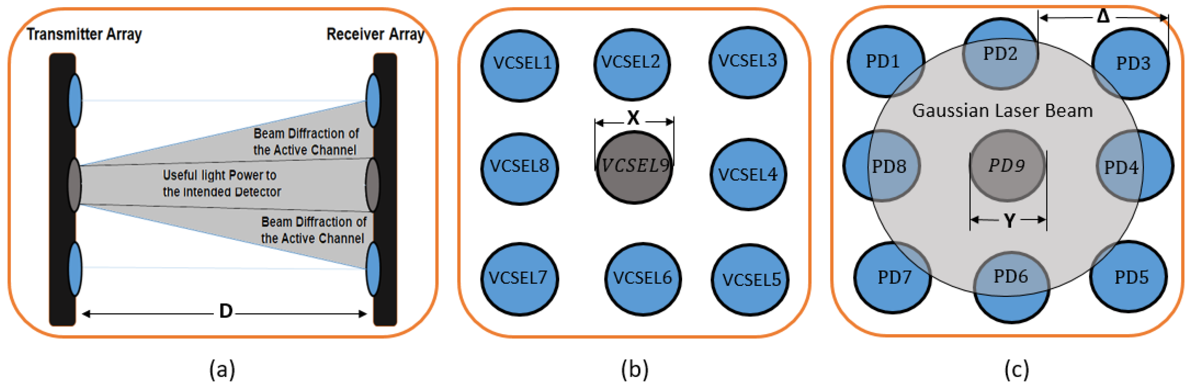
The FSOI system is composed of two arrays—one as a transmitter and the other as a receiver—with a given interconnect distance of D between the arrays; see
Figure 1a. The transmitter array contains nine identical transmitters of vertical-cavity-surface-emitting lasers (VCSELs) arranged as demonstrated in
Figure 1b. Likewise, the receiver array contains nine identical photodetectors (PDs) arranged as shown in
Figure 1c. The design parameters X, Y, and
marked on the figures represent the VCSEL’s and photodetector’s diameters and the channel spacing, respectively.
In fact, the exact number of channels, the distance between the source and detector arrays, and the other parameters of the FSOI system model depend on the application for which the system would be deployed. For example, in this study, we particularly used nine channels within a rectangular array shape to demonstrate the ability of using the rotational symmetry of the photodetector distribution to simplify the mathematical calculations of the crosstalk noise. From
Figure 1c, it is clear that the crosstalk noise received by photodetectors 1, 3, 5, and 7 is the same, and the crosstalk noise received by photodetectors 2, 4, 6, and 8 is also the same. In addition, it should be mentioned that we used rectangular source and detector arrays—not other possibly used shapes such as hexagonal or circular shapes—for many reasons. These include that rectangular arrays are simple and easy to fabricate, align, and scale to any size. Moreover, when it comes to processing the data received by each photodetector in the array, many signal processing and optimization techniques are naturally aligned with rectangular arrays [
27,
28,
29].
The proposed FSOI system does not utilize lenses in its design. Actually, using or not using lenses completely depends on the application and the FSOI system design parameters. For example, if we try to employ the system on small printed circuit boards, such as the ones used in smart phones, where the distance between the source and the detector arrays is in the range of millimeters, the laser beam diffraction could be negligible, and using lenses in such cases would be just a waste of resources. However, if the distance between the source and the detector arrays is large, like the one mentioned in [
30] where the distance between the arrays is in the range of 3 m, lenses might be used to mitigate the effect of optical interference.
The BD of an FSOI channel is defined as the ratio of the data rate (
) and channel spacing squared, which is written as [
19]
The relationship between the BD and the used SNR as well as the FSOI model parameters can be seen from the definition of
R, which is given by [
19]
where
represents the channel’s transmitted power,
is the optical power received by the intended receiver,
is the crosstalk noise, and
is the noise equivalent power that characterizes the amplifier thermal noise.
From (
1) and (
2), the BD of an FSOI channel can be determined by calculating
and
N for designated
,
, SNR, and
values. For example, the amount of
received by PD9 shown in
Figure 1c from VCSEL9 shown in
Figure 1b is computed by integrating the two-dimensional normalized optical intensity
at the surface of photodetector 9, which is placed at a distance
D from the transmitter. Assuming that the operating mode is the transverse electromagnetic
mode (TEM
), where
m is an integer that represents the radial mode order and
n is another integer that represents the angular mode order, then
can be formulated as
As in [
31], the optical intensity
of an operating mode TEM
at a plane located at
from a transmitter can be written as
where
is the spot size of the laser beam at the PD array located at a distance
D from the VCSEL array and is given by [
31]
where
is the beam waist at the transmitting laser, which is equal to
, and
is the wavelength of operation. The
and
is the Laguerre polynomial of order
and is defined as [
32]
Herein, we consider a laser beam with four modes of operation, which are the TEM
, TEM
, TEM
, and TEM
modes. In addition, we assume that the coupling among the laser modes is negligible. The normalized optical intensity of each mode, respectively, can be written as
and
where
,
,
, and
.
Upon substituting the optical intensities found in (
5)–(
8) into (
3), we can find the
received by the intended photodetector, which is in this case PD9, due to each mode separately.
The crosstalk noise (
) shown in
Figure 1c can be evaluated by finding the amount of incident power on the photodetectors that are not intended to receive the power from VCSEL9. The noise of the fundamental mode TEM
is defined as
where
and
. It should be mentioned that in (
9), we exploited the photodetectors’ distribution symmetry and the rotational symmetry of the laser beam. Therefore, the noise amount received by photodetectors 1, 3, 5, and 7 is the same, and the amount received by photodetectors 2, 4, 6, and 8 is the same as well.
For the other considered modes of operation—TEM
, TEM
, and TEM
, respectively—the noises of each are defined as follows
and
Upon calculating the values of and for each of the aforementioned modes, the BD can be determined for any given SNR, , and , as demonstrated numerically in the following section.
4. Bandwidth Density of Uncoded FSOI System
Herein, we demonstrate how the FSOI systems’ design parameters affect the bandwidth density (BD) without the use of coding. Particularly, we illustrate the channel spacing (
) and signal-to-noise ratio (SNR) effects on the bandwidth density under the operation of the fundamental-order Gaussian mode of the laser beam and the investigated higher-order modes. For all simulation results provided in this manuscript, we set the design parameters to be as follows: transmitted power per channel
of 50
W, operating wavelength (
) of 0.85
m, interconnect distance (
D) of 20 mm, VCSEL diameter (X) of 0.03 mm, noise equivalent power (
) of 0.1 nW/
, and PD diameter (Y) of 0.8 of the channel spacing (
) distance. It should be mentioned that the used design parameter values represent typical approximate values for the operation of VCSELs and photodetectors at room temperature [
1,
5,
33].
In
Figure 2, we illustrate the effect of
on the BD using the TEM
, TEM
, TEM
, and TEM
operating modes. These results were generated using a SNR of 10 dB. It is clear that each considered operating mode of the laser beam has an optimal channel spacing
value. For the fundamental-order Gaussian mode (TEM
), the
that achieves the maximum bandwidth density is 0.4 mm. At relatively small values of
(<
m), the BD of the system is quite small in comparison to the optimal BD; hence, it is not depicted on
Figure 2. For TEM
, TEM
, and TEM
modes, the
are 0.54 mm, 0.66 mm, and 0.9 mm, respectively.
Figure 3 shows a relationship between the BD and the SNR of the studied operating modes. Herein, we consider the
of each mode of the FSOI system equal to its
shown in
Figure 2. One can clearly see from the results that the BD is strongly correlated to the utilized SNR, and the relationship can be estimated as
. This suggests the employment of coding in order to enhance the BD, as demonstrated in the following section.
5. Bandwidth Density of Coded FSOI System
Error correction codes (ECCs) can be exploited in the FSOI systems’ design to introduce correction capability and enhance the operational BD. The system correction capability reduces the SNR level needed to obtain a desired bit error rate (
). Therefore, this capability of the system can be perceived in terms of SNR coding gain (
G), which is defined as the ratio of the SNR needed without coding over the one with coding
for a given BER [
18]. A variety of ECCs are available in the literature [
2,
20,
34], and they are characterized by the
G, where a high
G means good error correction capability. In this paper, we exploit Reed–Solomon (RS) ECCs of different codeword lengths to illustrate the effect of coding on the FSOI system BD. The characteristics of this type of codes are widely investigated in the literature, and the codes are exploited in many storage and communication systems [
35,
36,
37]. To demonstrate the consequence of RS codes on the BD of optical interconnects, we analyze their
G for a range of code rates, as shown in
Figure 4. The figure is generated based on the following formulations of
[
19,
38].
and
where
in (
13) and (
14) represents the Gauss error function, which is given by
.
The idea of using the
G curves to enhance the bandwidth density can be explained as follows: If we consider a codeword length (n) of 127 with a code rate of 0.64, then from
Figure 4, we find out that
G is 2.7. This indicates that the signal-to-noise ratio level utilized to obtain the findings of
Figure 2 can be decreased from 10 to 3.7 (
) while keeping the
without any change. This reduction in the level of SNR is converted into a gain in the BD
, which is given by [
18]
where
and
, respectively, are the uncoded BD and the effective BD (defined as the code rate multiplied by the coded bandwidth density
).
Figure 5 demonstrates the relationship between the
and the code rate for six different codeword lengths—7, 15, 31, 63, 127, and 255—with
dB. It is clear that the coding rate is a crucial parameter that influences the
upon coding and should be considered carefully in the design process. Low values of code rates provide a lot of redundancy, which in turn reduces the
. On the other hand, high values of code rates introduce inadequate error correction capability, which also limits the
. Therefore, a trade-off between high and low values of code rates should be considered. From
Figure 5, each codeword length has an optimum code rate that needs to be selected in the design of optical interconnects to achieve the optimal
. For example, when the codeword length is 31, the optimum code rate is about 0.6, and it is about 0.68 for a codeword length of 255. One more observation from
Figure 4 and
Figure 5 is that as the length of the codewords increases, the coding power improves in terms of both optimum coding gain and
.
In the following, we consider the dependence of the BD of the fundamental-order Gaussian mode (TEM
) of the laser beam and the other investigated higher-order transverse modes on coding.
Figure 6a demonstrates the BD of the TEM
mode before and after using Reed–Solomon error correction codes (RS-ECCs). The codes are used at the optimum data rates of each codeword length that is demonstrated in
Figure 5. From the figure, the optimum data rates of the codeword lengths 15, 31, 63, 127, and 255 are 0.59, 0.61, 0.62, 0.65, and 0.68, respectively. At the optimum data rates, RS-ECCs achieve the best possible improvement to the BD of optical interconnects. This improvement is due to the ability of coding to reduce the SNR required to obtain a given
, and in turn, this increases the BD of interconnects. In the simulation results presented in this paper, we used
dB, which means the
for codeword lengths of 15, 31, 63, 127, and 255 at their designated optimum data rates would be 5.4, 4.6, 4.0, 3.6, and 3.5 dB, respectively.
Figure 6b–d demonstrate the effect of using RS-ECC on the higher-order transverse modes TEM
, TEM
, and TEM
, respectively. It is clear from the results that increasing the length of the codewords leads to a direct increase in the BD. In addition, the optimal channel spacing that achieves the maximum BD is the same with and without coding for all investigated modes.


